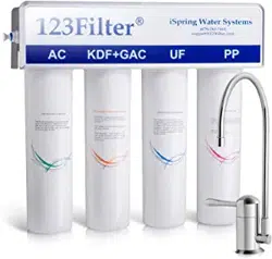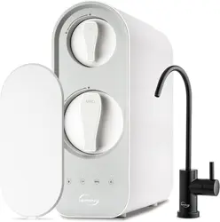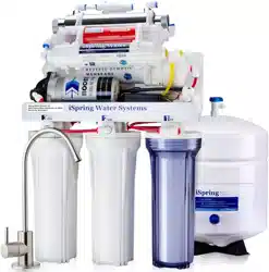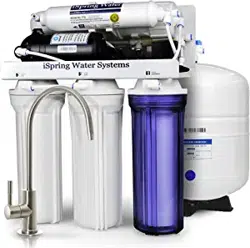
iSpring Reverse Osmosis Water Filtration Systems
INSTALLATION INSTRUCTIONS
& OWNER’S MANUAL Ver 02/2020
Copyright ©2005-2020 ISPRING WATER SYSTEMS, LLC. All rights reserved.

Page 1www.123filter.com | (678) 261-7611 | [email protected]
Thank you for choosing iSpring Reverse Osmosis Water Filtration Systems!
Built from quality components and delivering exceptional performance, this system has certified by WQA to
NSF/ANSI Standard 58 for the reduction of TDS, as verified and substantiated by test data. Please review
the attached iSpring RO System WQA Gold Seal Certification or the WQA website for details.
Please keep this owner’s manual for future reference.
It includes the necessary information on how to properly install, operate, and
maintain your iSpring Reverse Osmosis water filtration system.

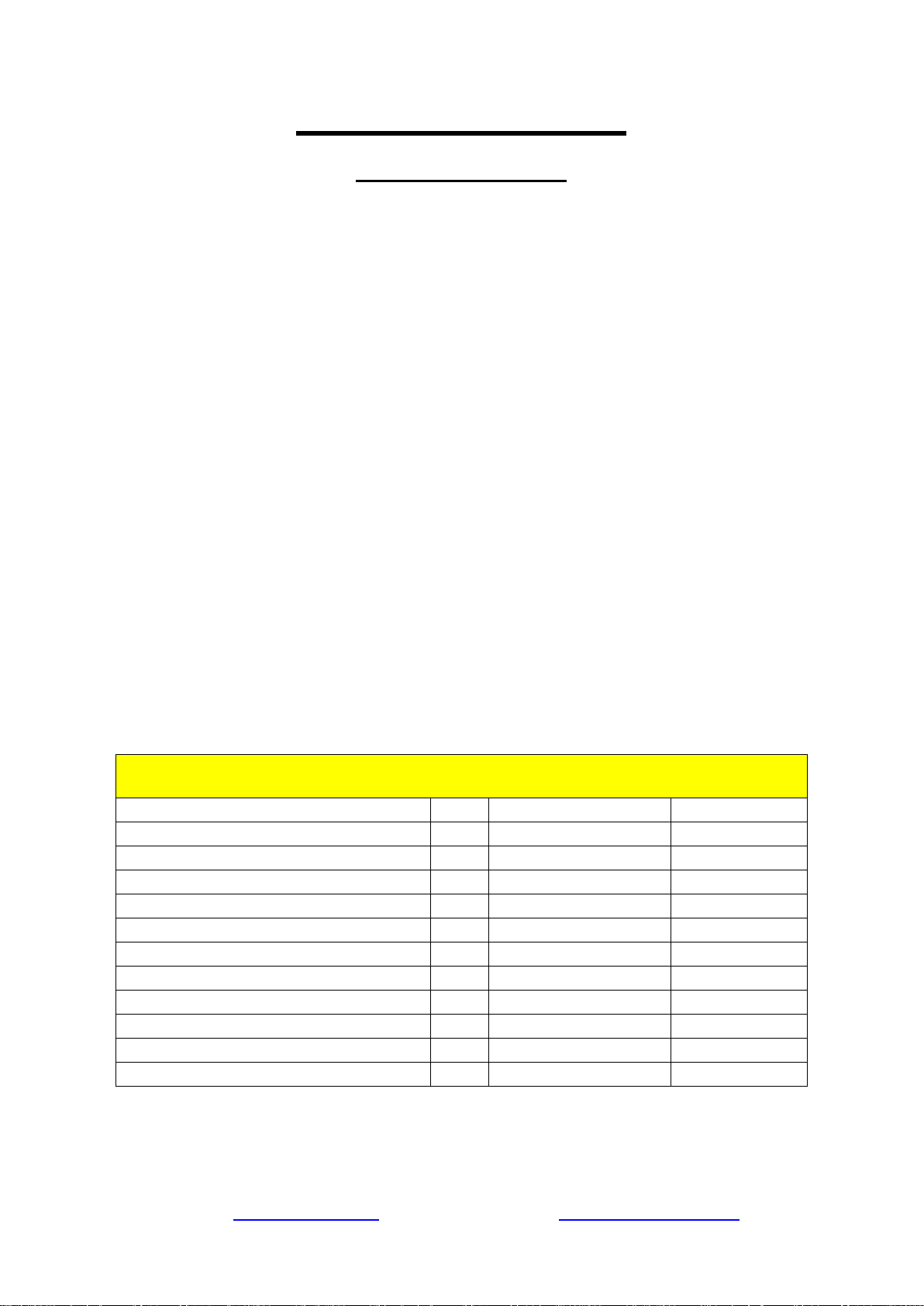
Table of Contents
System Installation
Prior to Installation ................................................................................................. 3
Component Identification ....................................................................................... 4
Understanding the Process...................................................................................... 5
Installation Tips ...................................................................................................... 6
Installation Steps ..................................................................................................... 8
Step 1: Installing the Feed Water Adapter ............................................................. 9
Step 2: Installing the RO Faucet ............................................................................. 9
Step 3: Installing the Drain Saddle ......................................................................... 9
Step 4: Installing the Vertical Filters: Stages 1, 2, and 3 ..................................... 10
Step 5: Installing theTank Shut-Off Valve ........................................................... 10
Step 6: Installing the Reverse Osmosis Membrane .............................................. 10
Step 7: Tubing Hook Up ....................................................................................... 11
Step 8: System Start Up ........................................................................................ 13
Owner's Manual
Section 1: iSpring RO System Maintenance ........................................................ 15
Section 2: Troubleshooting Guide for Newly Installed Systems ......................... 19
Section 3: Glossary and Terms to Know .............................................................. 21
Warranty
Warranty ............................................................................................................... 23
Warranty Registration ........................................................................................... 24
Page 3www.123filter.com | (678) 261-7611 | [email protected]
System Installation
Prior to Installation
*Installation is to comply with all local laws and regulations*
Inspect the package
Open the box and remove all of the components. Inspect them to ensure nothing was damaged during
shipping. If any part is cracked or broken, please immediately contact iSpring Customer Support for
replacement. Identify and get familiar with the components. Note, the RO membrane is a “wet” type, and it
is vacuum sealed with pure water.
Recommended tools list
● Variable speed drill with two bits: ¼” (for drilling a hole on PVC drain pipe), ½” hollow diamond
(for drilling a hole on countertop for drinking faucet)
● 5/8”, 9/16” open-end wrench, or adjustable wrench, pliers
● Phillips head screwdriver
● Scissors or utility knife
Operating conditions
● Minimum recommended water pressure: 30 PSI
● Maximum water pressure: 70 PSI, otherwise a pressure regulator (part no. APR70) is required to
lower the PSI to the maximum level.
● Operating water temperature range: 40 – 100 °F (4 - 37 °C) (This RO system is NOT designed for
HOT water). Within the operating range, the RO process will be faster and more efficient with the
water temp on the warmer side, and less so on the colder side.
● Maximum TDS: 750 ppm
● Install this RO system in a location where it is safe from hot/cold weather and direct sunlight. Avoid
hitting, dropping, or dragging the system as this can cause cracks and leaks.
The Requirements of the Influent Water Characteristics
Total Coliforms
None
Fluoride (mg/L)
1
Heat - resistant coliforms
None
Turbidity (NTU)
1
Escherich Coli
None
PH
>6.5 and <8.5
Bacterial colony count (CFU/ml)
100
Aluminum (mg/L)
0.2
Arsenic (mg/L)
0.01
Iron(mg/L)
0.3
Cadmium (mg/L)
0.005
Manganese(mg/L)
0.1
Chromium (Hexavalent)(mg/L)
0.05
Copper(mg/L)
1
Lead (mg/L)
0.01
Zinc(mg/L)
1
Mercury (mg/L)
0.001
Chloride (mg/L)
250
Selenium (mg/L)
0.01
Sulfate(mg/L)
250
Cyanide (mg/L)
0.05
TDS(mg/L)
1000
Fluoride (mg/L)
1
Hardness(mg/L)
450
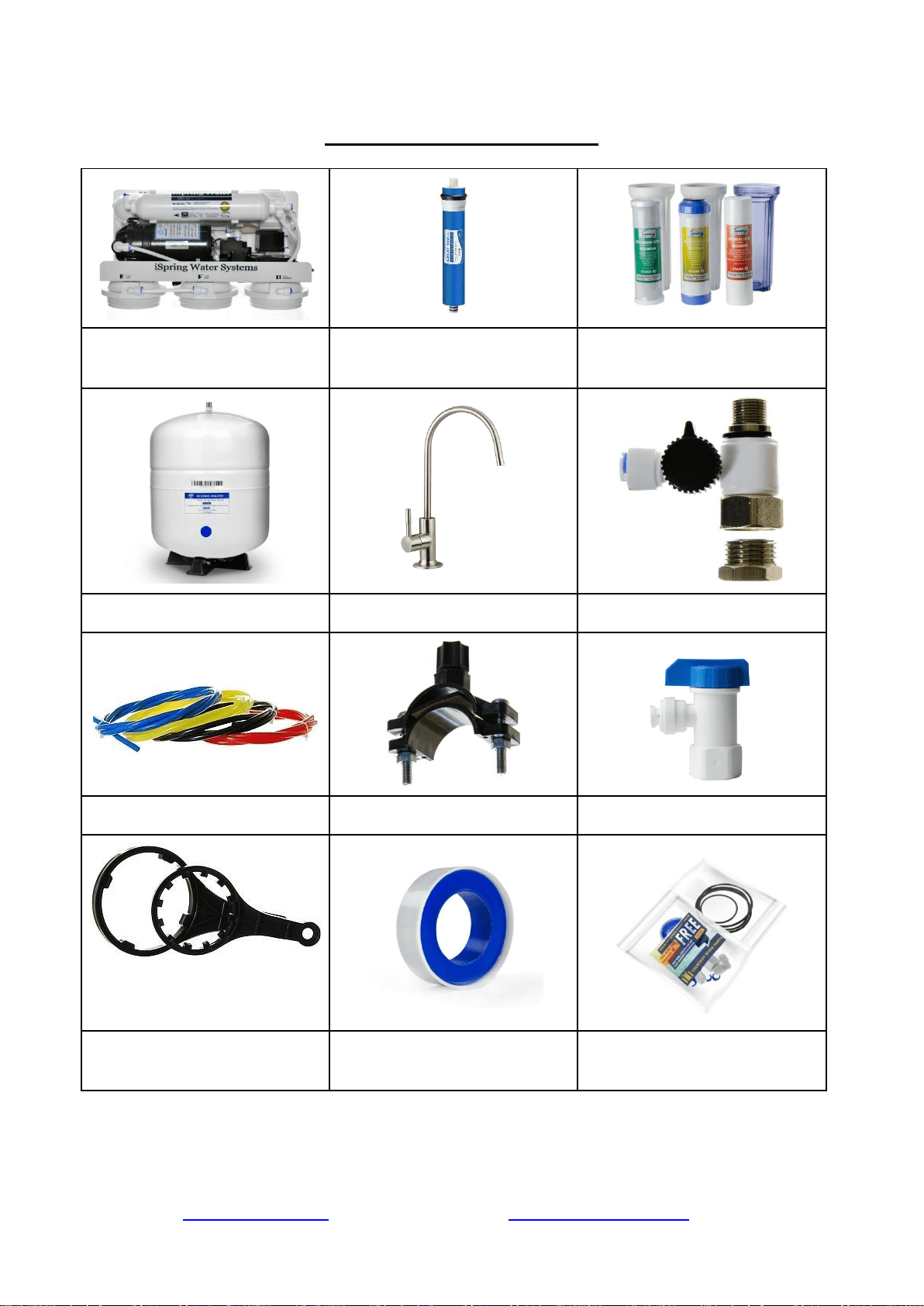
RO Machine Head w/ Pump
* (membrane not yet installed)
‘Wet’ RO Membrane
(Vacuum sealed in moisture)
3 Pre-Filter Housings and
Cartridges
Storage Tank
RO faucet with installation kit
Feed Water Adapter (AFW43)
4-Color Tubing Set
Drain Saddle ¼
Tank Valve
Housing Wrenches
Plumbers Tape
Spare O-Rings and Fittings
(Package quantity may vary)
* If your system is a 6-stage or 7-stage with an Alkaline, DI or UV filter, they already pre-installed
on the machine head.
Page 5www.123filter.com | (678) 261-7611 | [email protected]
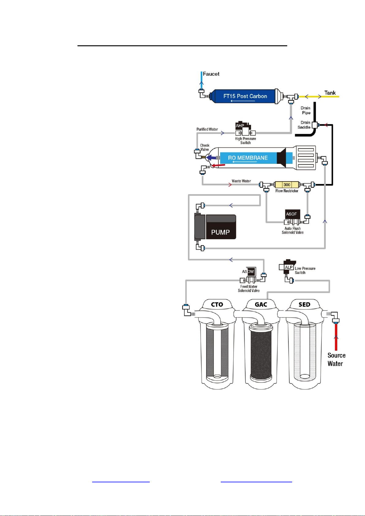
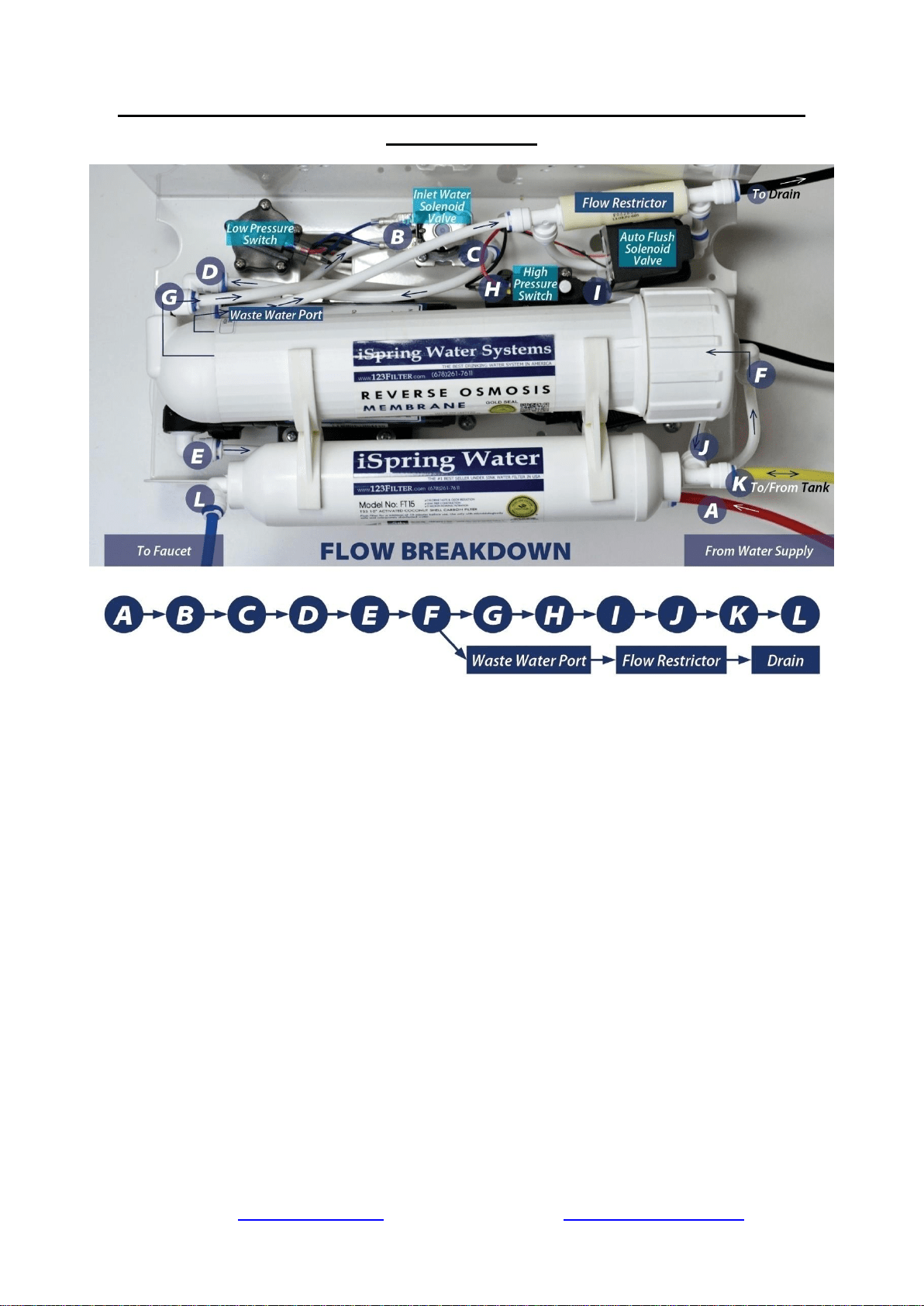
Understanding the Booster Pump and RO Process
1) Source water enters the system and
passes through the stage 1, 2, and 3 pre-
filters. Located between the pre-filters is
the Low Pressure Switch. This switch
turns on when the incoming water
pressure is 7 PSI or greater.
2) The High Pressure Switch turns on
when the pressure from the pressurized
tank is below 20 PSI, and turns off at 35
PSI (e.g. when tank is full).
3) When the Low Pressure Switch and
High Pressure Switch are both on, the
Feed Water Solenoid Valve opens,
allowing water to the Booster Pump.
4) The source water passes through the
Booster Pump, bringing it up to
approximately 80 PSI entering the
membrane housing.
5) Coming out of the RO membrane is a
pure water port and waste water port.
The RO water is forced through the
.0001 micron sized holes of the RO
membrane, and exits through the one
way Check Valve on the membrane’s
pure water exit port. The water rejected
by the RO membrane exits through the
waste water exit port. On the drain line
before the waste water is disposed is the
Flow Restrictor, limiting the amount of
drain water allowed out to keep pressure
in the system.
6) The pure water is then routed to the
pressurized storage tank. As the storage
tank fills, the tank pressure rises. When
the pressurized storage tank reaches 35
PSI, the tank pressure triggers the High
Pressure Switch off, shutting the booster
pump and system off.
7) When you open the RO faucet, the
water exits the tank, passes through the FT15 post carbon filter, and is dispensed from the
RO faucet. As the RO water is dispensed, the tank pressure will gradually drop back down,
triggering the High Pressure Switch back on to refill the water removed from the tank.
Installation Tips
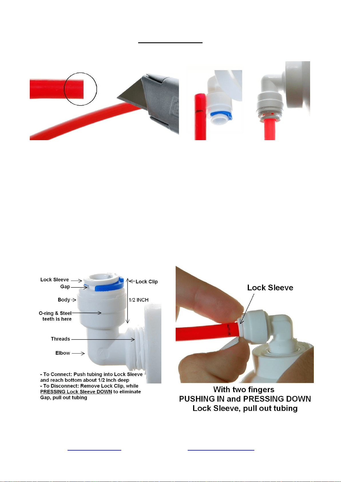
How to use the Quick-Connect fittings
Figure 1
To connect:
1. See Figure 1. Check and cut the tubing end squarely and cleanly with utility knife or
scissors.
2. Make a ⅝” mark at the end of the tube so you will be able to confirm when the tube is
inserted fully into the fitting.
3. Remove the blue lock clip from the fitting with your nail. If the lock sleeve pops out of the
fitting when doing this, simply pop it back in.
4. Insert the tube into the fitting until you reach the ⅝” mark on the tube. You will feel
resistance when the tube reaches the small rubber O ring inside the fitting. You will need to
wiggle the tube and apply additional pressure to get it past this O ring and create the seal. If
the tube is not ⅝” into the fitting and past the O ring, no seal will be created and
leaking will occur.
5. Once the tube is fully inserted into the fitting, pop the blue lock clip back on the fitting. This
will lock the tube in place and prevent it from moving.
Figure 2
Figure 3
Page 7www.123filter.com | (678) 261-7611 | [email protected]
To disconnect:
1. See Figures 2 and 3. Remove the blue lock clip from the fitting.
2. With the blue lock clip removed, use your thumb and index finger to hold down the lock
sleeve. This will release the metal teeth holding the tube in place. While holding the lock
sleeve down with that hand, use your other hand to remove the tube from the fitting.
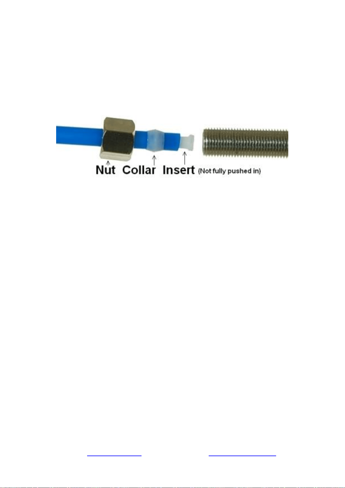
How to connect the compression fitting
A compression fitting is used to connect the PVC tubing to the threaded metal inlet with a tapered
open end, such as the refrigerator water inlet, etc.
Figure 4
1. Slide the brass nut and tube collar onto the tube.
2. Fully insert the tube insert into the end of the tube.
3. Slide the tube collar towards the tube insert until it stops.
4. Insert the tube into the tapered, open end of the threaded metal inlet as shown in the picture.
5. Screw on the brass nut and tighten it up. The brass nut compresses the plastic tube collar
onto the tapered metal surface and creates a water seal between them while the tube insert
stiffens the tubing.
How to drill a ½” hole in your sink or counter-top
1. It’s highly recommended to watch the YouTube video “How To Drill Faucet Holes” to
get a better understanding of the process. Depending on what kind of countertop you have,
you may want to hire an experienced professional to ensure the hole is drilled correctly.
2. Choose a half inch Diamond Core Bit for granite, and a titanium drill bit for steel. Do NOT
use a hammer drill on nature stone, glass, and ceramic.
3. An indent should be made with a punch on steel before drilling to help guide the bit.
4. Use caution when drilling on a Porcelain sink, as it could be easily chipped. Set drill speed
on slow. Press the bit downward firmly until breaking through the slippery surface. Some
people found it is easier to secure the bit by drilling through a piece of wood that is firmly
pressed on the surface.
5. Use coolant to disperse heat. Choose water for granite, and oil for steel. Use the Water
Suction Cup to hold coolant inside and prevent the drill bit from slipping.
6. Starting at slowest speed, hold the drill firmly and vertically and prevent the drill bit from
slipping on the counter.
7. Once breaking through the smooth surface, swirl the drill a little to apply pressure in a circle
evenly.
8. Be patient and deliberate. It can take 20 – 40 minutes to drill through one inch.
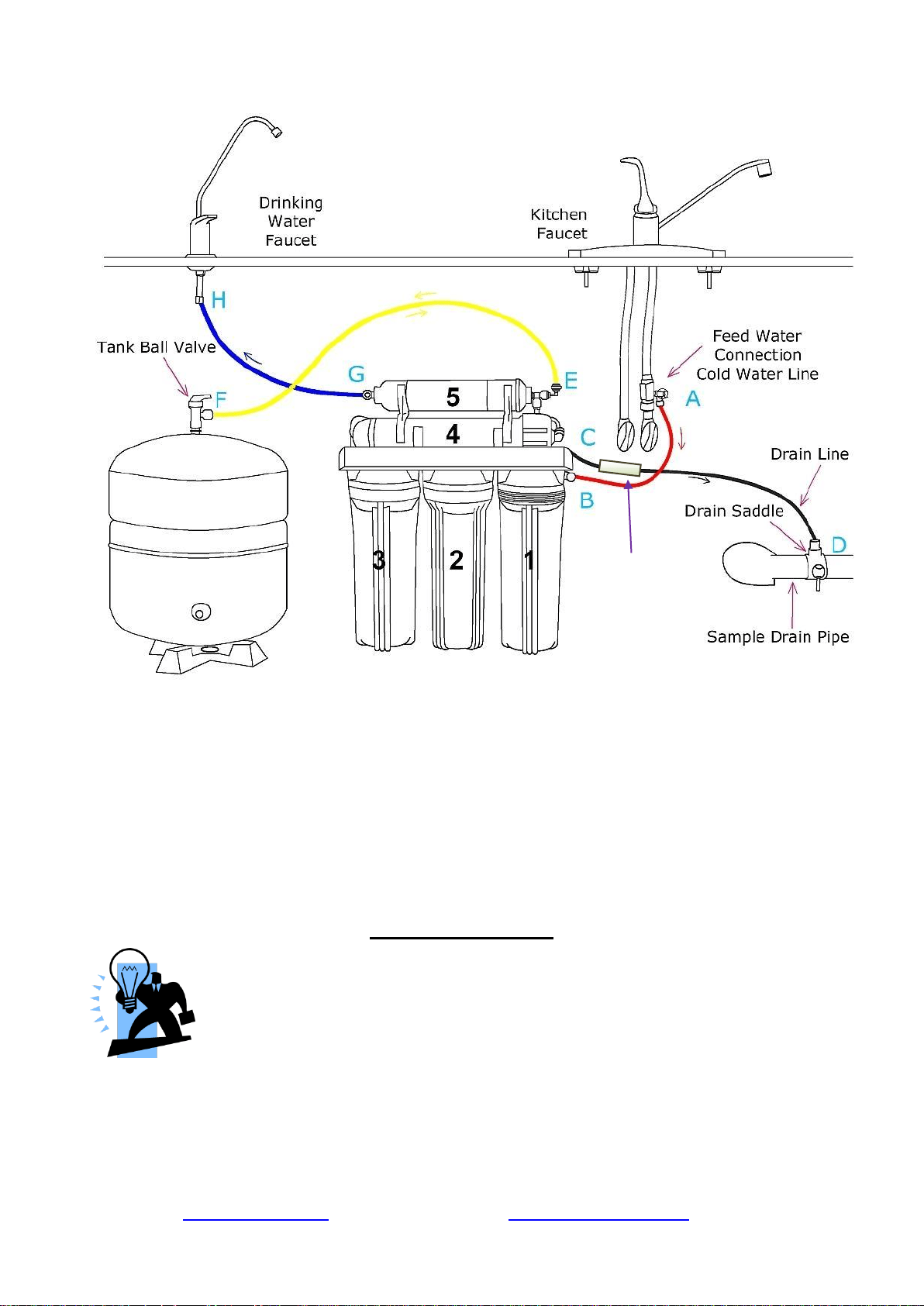
Sample Installation
Figure 5
A. Source water from Feed Water Adapter → B. Source water to 1st stage water inlet
C. Waste water from Flow Restrictor →D. Waste water to Drain Saddle/drain pipe
E. RO water from stage 5 “T” fitting → F. RO water to Storage Tank
F. When the drinking faucet is opened, RO water from the tank passes through E and G → H. RO
water to the drinking faucet
*Note, diagram represents a faucet with non-air gap installation. There is a one valve present on the
pure water line, and the flow restrictor doubles as one way valve preventing drain water from
entering back into the system.
Installation Steps
Before you begin the installation, it is highly recommended that you watch the
video “iSpring Reverse Osmosis Installation” on YouTube.
Note: If you plan on mounting/hanging the system, it is highly recommended to
include supports under each of the bottom three housings. Supports under the
housings will take the water weight off the housing threads, and ensure the thread strength does not
decay over the years.
Note: The booster pump (and UV stage if applicable) should remain unplugged until directed.
Note: Steps 1 – 7 are independent, and can be performed in any order.
Flow
Restrictor
Page 9www.123filter.com | (678) 261-7611 | [email protected]
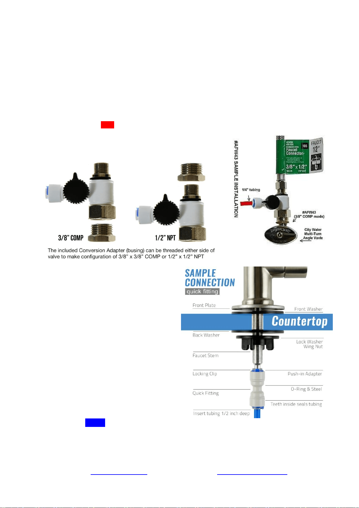
Step 1: Installing the Feed Water Adapter (AFW43)
(The bushing can convert 3/8” comp. to ½” NPT. Refer to AFW43 user manual)
1.1 See Figure 5. Turn off the Cold Water Line via the Cold Water Supply Valve (CWSV) under the sink.
Open the kitchen faucet to release any pressure and make sure the water has stopped before proceeding to
the next step. Get a towel or bucket to catch any water drips. Disconnect the Kitchen Faucet Connector
(KFC) pipe from the CWSV.
1.2 Check to make sure the O-ring is seated inside the AFW43 female end, and twist it onto the CWSV.
Tighten it using a wrench or pliers.
1.3 Twist the KFC onto the male end of the AFW43. Turn the handle of the AFW43 to the perpendicular
OFF position. Turn on the CWSV slowly, and ensure you are getting a proper seal.
1.4 Connect the 1/4” RED tubing to the AFW43.
Feed Water Adapter with Bushing to convert 3/8” COMP to
½” NPT
Step 2: Installing the RO Faucet
2.1 If your kitchen sink does not have an
existing ½” faucet hole, you will have to
drill one. (Refer to How to drill a Hole
on Sink or Counter-top). Wipe clean and
dry the area.
2.2 Slip the front plate on the faucet stem,
followed by the rubber washer. Insert the
faucet stem into the hole on the
countertop. Under the sink, slip on the
back rubber washer, and tighten the nut
with the plastic wing.
2.3 Slide the quick connecting up the push-
in adapter on the base so that it seats
securely into the faucet stem, then lock it
in place by sliding the blue clip under
the collet.
2.4 Insert the BLUE tubing about 1/2 inch into the push-in fitting, and again, secure it with the
blue clip.
How to install an Air-gap Faucet (optional)
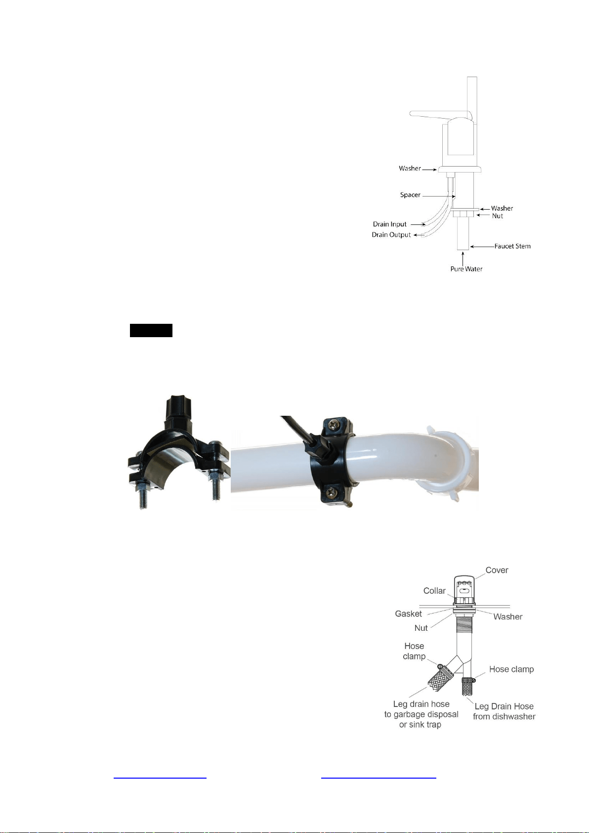
Note: The installation instructions below are for your reference only. An air gap faucet is not
included with this system.
• Drill a hole in the kitchen sink or countertop if there isn't
already a spare one. Refer to the manual of
the faucet when determining the size.
• Place the front plate and the rubber washer on the base
of the faucet. Mount the faucet into the countertop.
• From under the sink, connect the RO system pure water
output line to the faucet stem. Attach the black drain line
from the RO system to the drain input barb. Attach one
end of the faucet drain line to the drain output barb and
the other end to the drain saddle on the drain pipe.
Assemble the hardware according to the faucet manual.
Step 3: Installing the Drain Saddle
3.1 Choose a spot on the drain pipe that is convenient for installing the drain saddle and tubing.
A horizontal pipe is recommended to minimize the dripping sound.
3.2 Drill a 1 /4” hole in the drain pipe, and paste the black sticky pad around the hole.
3.3 Cut the BLACK tubing end to make a 45 degree angle. Slip the plastic nut and front plate
on the tubing. Insert the tubing into the 1 / 4” hole in the drain pipe, install the back plate,
and tighten the two screws with hex nuts while the tubing remains in the hole.
3.4 Tighten the nut on the Drain Saddle by hand. Pull the tubing lightly to make sure it is
secure.
Install the Air Gap (optional)
Note: If your sink does not have an unused hole for mounting the air gap body, bore a hole
depends on the size of the air gap body next to the sink using an electric drill and hole saw.
• Remove the cover and collar from the top of the air
gap body. Leave the gasket, washer, and nut threaded
to the bottom of the air gap body.
• Attach the drain hose from the dishwasher to the leg.
Secure with a stainless steel hose clamp.
• Attach the drain hose from the garbage disposal or
side inlet piece of the sink trap to the leg. Secure with
a stainless steel hose clamp.
• Push the air gap body up through the unused hole of
the sink rim or countertop. Approximately 2-1/4” of
the air gap body should appear above the sink rim or
countertop.
• Securely tighten the nut and collar against the sink rim
or countertop. Place the cover over the air gap body.
Page 11www.123filter.com | (678) 261-7611 | [email protected]
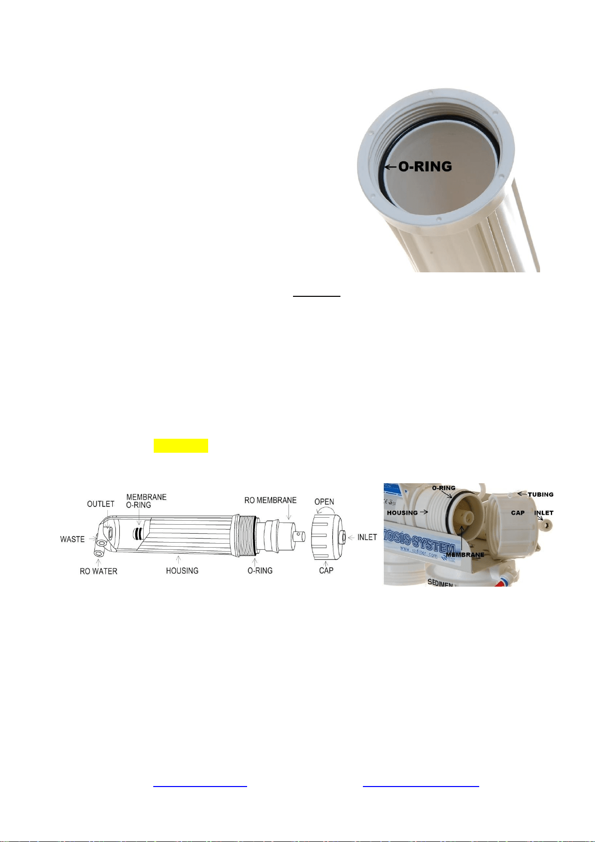
Step 4: Installing the Vertical Filters: Stages 1, 2, and 3
4.1 Make sure the O-ring is seated inside the groove on
top of the filter housing. (Figure 10). A light amount
of food-grade silicone jelly may be used to help the
O-ring seal better, but is not required.
4.2 The filter cartridges are preserved in shrink wrap.
Note the direction sign on the sticker before
removing the wrap.
4.3 When placing the filter cartridge into its housing,
make sure it is centered and the knob protruding
from the bottom of the housing fits in the central
hole of the filter.
4.4 Screw the housing, with filters attached, onto the
housing caps (caps are pre-assembled on the
machine head). The cap also has a center knob
which should be inserted into the center hole of the
filter cartridge. Twist the housing on in a clockwise direction by hand, and then use the
housing wrench to tighten it another 1/4 – 1/2 of a turn. Do not over tighten. This can
cause leaks and make it difficult to unscrew the housing when replacing filters.
4.5 Follow steps 1.1 – 1.4 to install the GAC and CTO filters. *Note* the second stage GAC is
the only filter that must go in a certain direction. Make sure the end with the rubber washer
faces up, thereby attaching it to the housing cap.
Step 5: Installing Tank Shut-Off Valve (TSV)
5.1 Wrap 10 - 15 wraps of Teflon tape clockwise (when looking from above) onto the metal
thread at the top of the tank.
5.2 Screw (clockwise) the Tank Shut-off Valve on and tighten it by hand. Do not over tighten.
5.3 Connect the YELLOW tubing into the Quick-Fitting on the TSV.
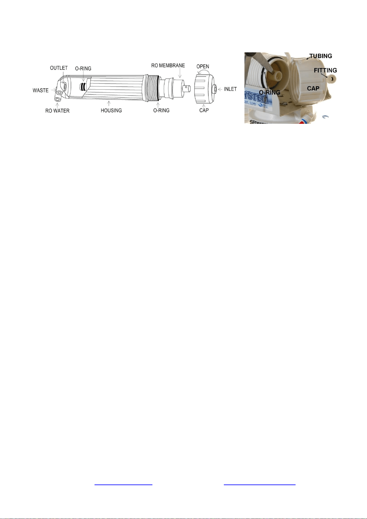
Step 6: Installing the Reverse Osmosis Membrane
Figure 8 Figure 9
6.1 First, disconnect the white tube from the quick-fitting connection on the membrane cap.
This will allow you to unscrew the membrane housing cap.
6.2 All the systems are wet tested without filters prior to shipment, so you may notice some
water drops still inside the housing.
6.3 Unscrew (counter clockwise) and remove the membrane cap.
6.4 Note: the membrane is a “wet” membrane, and comes vacuum sealed wet with pure water.
Following the flow direction sign on the membrane, cut open the “small end” of the bag,
hold the membrane with the bag to avoid touching or contaminating it, and firmly insert it
into the housing. This way the end with the two small black O-rings towards the
bottom. When it is inserted fully and properly, the “bigger” end of the membrane will be
even with the housing opening. See Figures 8-9. After the membrane has been fully inserted
you may then disregard the bag.
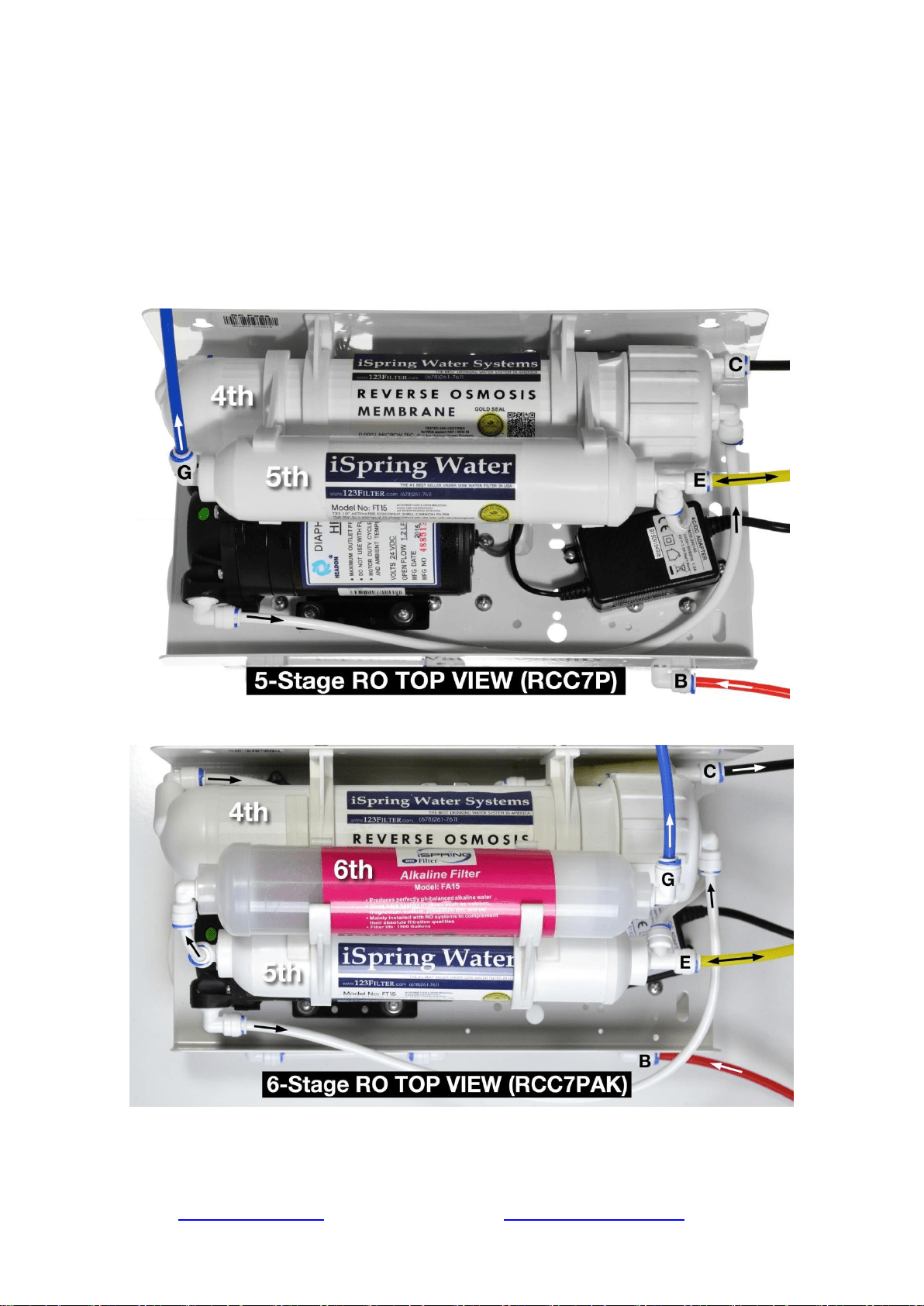
6.5 Before twisting the housing cap back on, make sure the O-ring is seated at the end of the
membrane housing as shown in figures 8 and 9. This is very important to avoid leaking
and damage to the O-ring.
6.6 Place the membrane housing cap back on and hand tighten it, then use the housing wrench
to tighten it another ¼-½” of a turn. Do not over tighten.
6.7 DO NOT reconnect the tubing to the fitting on the cap at this point (will be done in system
start up).
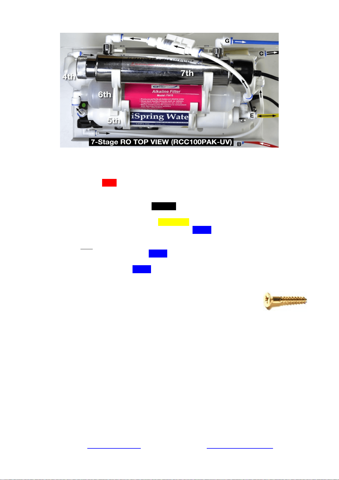
Step 7: Tubing Hook Up (see figure 5 above to see letters not shown below)
Page 13www.123filter.com | (678) 261-7611 | [email protected]
7.1 See figure Sample Installation and figures of system top view, and note connection points
A-B, C-D, E-F, and G-H.
7.2 Facing the front of the system, 1st stage is the see through housing located on the right hand
side. Connect the RED tubing Feed Water Adapter (AFW43) (point A) to the stage 1 elbow
fitting (point B).
7.3 Connect the Flow Restrictor (point C, 3-inch long cylinder with a FLOW labeled on it) to
the Drain Saddle (point D) with the BLACK tubing.
7.4 On the right side of the Post Carbon Filter (FT15, 5
th
stage), connect the T-fitting (point E)
and the Tank Valve (point F) with the YELLOW tubing.
7.5 At the left end of the stage 5 FT15 filter, insert the BLUE tubing (links to RO faucet) into
the elbow fitting.
* Models with UV/AK/DI: RO water flows out of point G at FT15 and flows into the input
(left) side of the next stage. So the BLUE tubing should be connected to the output side of
the final stage.
7.6 Connect the other end of the BLUE tubing to the RO faucet (refer to How to Use the
Compression Fitting).
7.7 You may neatly organize the tubing, but make sure to leave enough length so the filter
system can be moved freely in and out of the cabinet when replacing
filters.
7.8 You can mount the system using two 10 x 1-1/4 Phillips Flat Wood
Screws. This will make replacing filter cartridges easier. Note: If you plan on
mounting/hanging the system, it is highly recommended to include supports under each of
the bottom three housings. Supports under the housings will take the water weight off the
housing threads, and ensure the thread strength does not decay over the years.
Step 8: System Start Up (model specific sub-steps are marked with a *)
Note: You may now plug in the booster pump to an outlet. The pump will not turn on until
water is flowing.
* If your model has a UV stage, do not plug in the UV power until the system has been fully
flushed.
8.1 Make sure no tubings are kinked. Turn the Tank Shut-off Valve OFF (perpendicular to
the yellow tube). Place a towel under the system to catch any possible water leaks.
8.2 To prevent any residual carbon from the carbon pre filters from getting into the RO
membrane, you previously left the tubing to the inlet of the RO membrane housing cap

disconnected. Open the Feed Water Adapter Valve (AFW43) and Cold Water Supply Valve
(CWSV), and flush the first three stages into a bucket until the water turns clear.
8.3 Once the water is clear, shut off the AFW43 and reconnect the tubing to the RO membrane
housing cap. You will want to flush the first three stages like this whenever they are
changed.
8.4 Open the RO faucet. Slowly open the AFW43 back up and check for any leaks. The top 3
causes of leaks are 1) The tubing is not fully inserted into the quick-connect fitting. 2)
The O-ring is not in the correct place or is kinked. 3) The Housing/Cap is not
tightened properly or is misaligned with the threads.
8.5 Within 5 minutes, the booster pump will kick on and RO water will start slowly trickling
from the faucet. Let the faucet trickle for at least 15 minutes to flush out the entire system
apart from the tank. The water may appear black at first due to loose carbon from new
carbon filters. It will eventually turn clear apart from many tiny air bubbles leaving the
system.
8.6 Shut off the RO Drinking Faucet. Open the Tank Shut-off Valve. Wait for the tank to fill up
completely. It will take 1 to 2 hours depending on your water temperature (40F-100F, the
warmer the faster) and source water TDS (up to 750 ppm, the lower the faster). The pump
will shut off automatically when the tank is full.
8.7 After the tank is full, open the RO Drinking Faucet to drain the tank completely. Do not use
the first tank of water. Let it drain into the sink until the stream turns back to a trickle. This
means the tank has emptied and you can close the RO faucet to let it begin filling again.
8.8 * If your system has a UV filter, plug in the UV power and check to make sure the UV light
is turning on when water flows through it. The UV filter has a Flow Sensor Switch that
detects water flow and only turns the light on when needed. If the UV is not turning on
when water flows through, confirm the power source you are using has power. Typically,
the garbage disposal outlet only has power when the disposal is switched on.
8.9 The TDS (total dissolved solids) of the water should be tested periodically to verify that the
system is performing properly. iSpring RO systems have earned WQA GOLD SEAL by
exceeding the minimum requirements for NSF/ANSI standard 58 and should be giving an
average TDS reduction rate of 90%+, so if your tap water is 100ppm you should be getting
10ppm or less from the RO water (200/20>, 400/40> etc.). This reverse osmosis system
contains a replaceable treatment component, critical for the effective reduction of total
dissolved solids and that product water should be tested periodically. TDS is measured with
a TDS meter - it is an inexpensive, easy to use device that can be found on Amazon.com or
123filter.com by searching “iSpring TDS”.
8.10 Check for leaks daily for the first two weeks after installation to ensure the system is
functioning properly. Install the included Flood Alarm to provide additional peace of mind
and protection.
Note: Do not use with water that is microbiologically unsafe or of unknown quality without
adequate disinfection before or after the system. Systems certified for cyst reduction may be used
on disinfected water that may contain filterable cysts.
Congratulations, you have successfully installed your
iSpring Reverse Osmosis Water Filtration System!
Start enjoying fantastic reverse osmosis water right from your tap!
-------------------------------------End of Installation Section------------------------------------

Page 15www.123filter.com | (678) 261-7611 | [email protected]
OWNER’S MANUAL
Please read this manual for useful reverse osmosis system maintenance information.
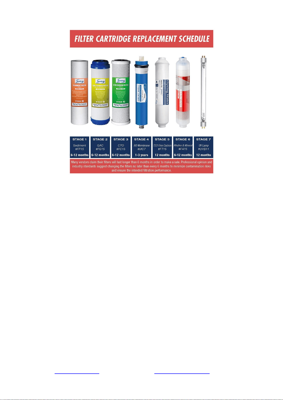
Section 1: iSpring RO System Maintenance
All iSpring RO systems are designed with ease of use and low maintenance in mind. If the filter
cartridges are changed on schedule as suggested, the system will work properly for years to come.
See the chart below for the filter pack model numbers for your system. The filter packs can be
found on 123filter.com, Amazon, or HomeDepot.com.
This reverse osmosis system contains a replaceable component critical to the efficiency of the
system. Replacement of the reverse osmosis component should be with one of identical
specifications, as defined by the manufacturer, to ensure the same efficiency and contaminant
reduction performance.
System Model
1-Year Filter Pack
2-Year Filter Pack
3-Year Filter Pack
RCC7, RCC7P
F7-GAC
F15-75
F22-75
RCC7AK, RCC7P-AK
F9K
F19K75
F28K75
RCC7AK-UV
F10KU
F21KU75
F31KU75
RCC7D
F9D
F19D75
F28D75
RCC7U
F8U
F17U75
F25U75
RCC1P
F7-GAC
F15-100
F22-100
RCC1PAK
F9K
F19K100
F28K100
RCC1UP
F8U
F17U100
F25U100
RCC1UP-AK
F10KU
F21KU100
F31KU100
RCW5
F7-GAC
F15-50
F22-50
Please see the WQA website for a list of certified models.
Note: Stages 6 and/or 7 only exist on certain models.
Stage 1 – 3 Pre-Filters
Replace every 6 months or sooner if you notice a decrease in water flow or quality. The
replacement frequency depends on your water usage and source water quality. To protect the RO
membrane from chlorine and other damaging contaminants, it is important to change the pre-filters
according to schedule.
How to change the stage 1 – 3 pre-filters:
1. Shut off the cold water supply valve and tank valve, and open the RO faucet to depressurize
the system. Place a bucket or towel under the system to catch any water spills.
2. If there is enough room under the sink and the filter system is hung on the wall, you can
twist the filter housing off without removing the system from the wall. Otherwise, you will
need to pull the system out, lay it down, and remove the housings at that point. Be careful
with the tubing connections when removing the system.
3. Twist off the filter housings in a counter-clockwise direction using the filter housing
wrench.
4. Refer to Installation Step 1.1 to install the new vertical filter cartridges, and tighten the filter
housings back on. Remember not to over tighten them or they will be hard to unscrew next
time.
Stage 4 RO Membrane
Replace every 2-3 years or sooner if the TDS level starts increasing. Check the TDS level at least
once a month to monitor the system’s performance. The TDS rejection rate should be 90%+. To
calculate the rejection rate, divide the RO water TDS into your tap water TDS and subtract from 1.
For example, 20 (RO TDS) / 200 (Tap water TDS) = 0.1 1-0.1 = 0.9 so the TDS rejection rate
would be 90%. (NSF/ANSI STANDARD 58 for RO water filter).
Page 17www.123filter.com | (678) 261-7611 | [email protected]
How to Change the Reverse Osmosis Membrane
Figure 11
Figure 12
1. The RO membrane typically lasts about 2 – 3 years. The membrane life span depends on the
source water quality, your water usage, and how often the three pre-filters are replaced. To
ensure the system’s performance and water purity, it is important to replace the pre-filter
cartridges on schedule. Use a TDS meter to periodically check the RO water purity.
2. Shut off the cold water supply valve and tank valve, and open the RO faucet to depressurize
the system. Place a bucket or towel under the system to catch any water spills.
3. Remove the tubing from the quick-connect fitting on the membrane housing cap. Use the
membrane housing wrench to twist off the housing cap in a counter-clockwise direction.
4. Pull out the old membrane. Use scissors or pliers to apply leverage if necessary.
5. Clean the membrane housing using hot water and scent-free dish soap (optional). Rinse
thoroughly.
6. Cut open the small end of the vacuum sealed packaging containing the new RO membrane.
Hold the new membrane through the packaging, and insert it into the housing without
touching the membrane with your bare hands to avoid contamination of the membrane.
7. Make sure the O-ring is properly seated on the end of the membrane housing as shown in
the previous images. We recommend replacing the O-ring every 3 years to prevent leaking
due to an expired or dried out O-ring.
8. Place the membrane housing cap back on and hand tighten it, then use the housing wrench
to tighten it another ¼-½” of a turn. Do not over tighten.
Stage 5 FT15 Inline Post Carbon Filter and Stage 6 FA15 Inline Alkaline Filter
Replace the FT15 every 12 months and the Alkaline filter every 6 months
1. Remove all quick-connect tubing connections from the FT15 Post Carbon Filter.
2. Unscrew the fittings from both ends of the old Post Carbon Filter. Wrap the thread of each fitting 2-3
times with Teflon tape, and screw them into their respective sides on the new Post Carbon Filter.
3. Reconnect the quick connect tubing connections to the new Post Carbon Filter.
Tank Maintenance
It is recommended to fully empty and refill the tank at least once a month. This keeps the water
inside the tank fresh and not sitting for an extended period of time.
What should I do with the system when going out of town?
When you are leaving for an extended period of time, you will want to shut off the water supply to
the system and empty the tank. To do this, close the knob on the feed water adapter, and open the
faucet until it stops running. This will signify that the tank is empty. The filters should be replaced
if the system is not used for over a week as they will be sitting in stagnant water.
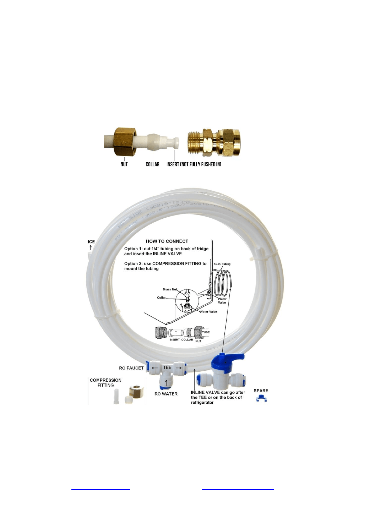
Optional Add-Ons
Ice Maker Kit (ICEK)
The Ice Maker Kit (model#: iSpring ICEK) can be purchased separately to feed RO water to your
refrigerator for crystal clear ice cubes and great tasting water. If you choose to hook up the system
to your refrigerator output, it can take the place of primary output over the RO faucet.
Page 19www.123filter.com | (678) 261-7611 | [email protected]
Section 2: Troubleshooting Guide for Newly Installed Systems w/
Booster Pump
1) Zero output water from RO faucet
a) Water supply is closed. Open the water supply to the system so the valve is in line with the
red tubing.
b) Incorrect installation. Verify all tubing connections.
c) The pump is not running, therefore not allowing water through. Make sure the pump is
plugged into a live outlet that gets continuous power.
d) A tubing is crimped, blocking the water flow. Check all tubings and uncrimp any crimped
tubings.
2) Tank not filling after several hours
a) Pump is not running, therefore not allowing water to pass through. See “Pump does not
start”.
b) Incorrect installation. Verify all tubing connections.
c) Tank valve is closed. Make sure the tank valve is in line with the yellow tubing.
3) Leaking from where the tubings are inserted into the fittings
a) The tubing is not pushed in past the O-ring inside the fitting, therefore not creating a seal.
Make sure the tubing is pushed in a full ½” into the fitting. It will take some extra pressure,
but you will feel the tube go fully into the fitting when it does so.
b) The O-ring inside the fitting is not creating a seal with the tubing. Unscrew the elbow
fitting, and replace it with one of the spare elbow fittings. Make sure to wrap the new fitting
thread several times with Teflon tape before screwing it in.
4) Leaking from between the membrane cap and membrane housing

a) If the membrane housing is leaking, make sure the O-ring is seated correctly as shown in
sections “Installing the RO Membrane” and “How to Change the RO Membrane”. It should
be seated on the end of the membrane housing before the threads begin. The membrane cap
is then screwed on over it. When positioned incorrectly, it will create a gap or damage the
O-ring. When in the correct place, there will not be any pressure or tension on the O-ring.
5) Low water flow (trickle) at RO faucet
a) Tank has not been given the chance to fill. Allow approximately two hours for the tank to
fill.
b) Tank valve is closed. Make sure the blue tank valve is in line with the yellow tube.
6) High TDS in RO water
a) The system will provide a 90%+ TDS rejection rate when working properly. Meaning if
your tap water TDS is 500 ppm, the water from the system should be 50 ppm or lower.
b) Incorrect installation. Verify all connections on the system.
c) If the TDS of the tap water and water from the system are about the same, make sure the RO
membrane is in fact installed. The semi permeable membrane is blue, comes in sealed
packaging, and goes in the stage 4 membrane housing.
d) If you are getting some reduction in TDS but not 90%+, some water could be bypassing the
membrane. Contact iSpring customer support to identify the exact cause.
7) Cloudy water after installation
a) In the weeks after installing the system or changing the filters, you will see many tiny air
bubbles in the RO water. This can cause the water to appear “cloudy”. The bubbles will
disappear as the system clears itself of trapped air, and are harmless for the time being.
8) The system drains water 24/7 (continuous drain)
a) Keep in mind that it will take anywhere from 1-3 hours for the system to fill the tank from
empty, and the drain line will be trickling during this time. If the drain line continues to run
for 4+ hours, one of the following reasons could be the problem.
b) The pump is running 24/7. See “Pump runs 24/7”.
c) The inlet water solenoid valve is bad and is unable to shut off the incoming water supply.
9) Leak from tank valve connection
a) Make sure you have applied Teflon tape to the tank threads before screwing on the tank
valve. There should be at least 8-10 wraps of Teflon tape to ensure a proper seal. If you have
done this and it continues to leak, contact iSpring customer support for a replacement.
10) Water from the system tastes the same as tap water
a) Incorrect installation. Verify all connections on the system.
b) The RO membrane is not installed in the housing. Ensure the membrane has been installed.
11) Pump does not start
a) No power. Make sure the pump is plugged in. If it is plugged in and still not kicking on,
make sure it is not plugged into the same outlet as the garbage disposal. Typically this outlet
only has power when the garbage disposal is switched on.
b) Incoming water pressure is below 30 PSI. The low pressure switch kicks on the booster
pump at 30 PSI, and if this pressure is not reached then the pump will not turn on.
c) Low pressure switch is not functioning correctly and is therefore unable to turn the pump
on.
12) Pump runs 24/7
a) If the pump is running 24/7 and the output flow remains normal, the high pressure switch is
faulty and not triggering the pump to turn off.
b) If the pump is running 24/7 and you are getting little to no output flow, either the check
valve is losing pressure or the pump itself is faulty.
c) Tank pressure is too low, never reaching the pressure requirement to shut the pump. Empty
the tank and set it between 7-10 PSI and reconnect.

Page 21www.123filter.com | (678) 261-7611 | [email protected]
Section 3: Glossary and Terms to Know
Add-On Kit (#ACL1): Filter add on kit for adding additional in line filters to an existing system. Comes
with quick-connect elbow fittings, filter clamps, and additional tubing
Alkaline Remineralization Filter* (#FA15): 6th stage. Remineralizes the RO water and neutralizes the pH
Auto Flush Solenoid Valve (#ASOF7): Automatically flushes the RO membrane to preserve membrane life
and efficiency
Booster Pump (#PMP5): 24 volt booster pump used by residential iSpring RO systems
Check Valve (#ACV1K): One way valve that does not allow water back into the membrane housing. Looks
like a standard elbow fitting and is located on the RO water port of the membrane housing
CTO Carbon Block Filter (#FC15): 3rd stage. 5 micron 10” carbon block filter. Further reduces any
residual chlorine, tastes, and odors before the water reaches the RO membrane
Drain Saddle (#ADS1): Attaches to your under-sink drain pipe to secure the drain tube coming from the
system
Drinking Faucet (#GA1-BN): The output source for the RO water. The faucet is a non-air gap faucet with a
¼” tubing connection. The optimal sized counter-top hole for the faucet is ½”, but holes up to approximately
1 ½” will work
Elbow Fittings (#4044K): Quick connect elbow fittings used on the system (except for on the membrane
housing and cap). ¼” tubing connection and ¼” NPT male thread
Elbow Fittings on Membrane Housing (#4042K): Quick connect elbow fittings used on the membrane cap
and drain port of the membrane housing. ¼” tubing connection and ⅛” NPTF male thread
Feed Water Adapter (#AFW43): Goes in line with your cold water line and branches off a water supply
line to the RO system. Can adapt to ⅜” and ½” cold water lines
Feed Water Solenoid Valve (#ASOW7): Opens the water supply to the booster pump when the low
pressure switch and high pressure switch are both on. Shuts off the water supply when one or both turn off
Flow Restrictor (#AFR300): Limits the drain water flow, keeping pressure in the system and allowing the
RO process to occur
Flow Sensor Switch* (#FSS): Detects water flow to turn the UV filter on and off as needed
GAC Filter (#FG15): 2nd stage. 5 micron 10” granulated activated carbon filter. Reduces chlorine, tastes,
and odors from the water
GPD: Gallons Per Day
High Pressure Switch (#ALP1): Receives pressure signals from the pressurized storage tank. Turns on
when the tank pressure is below 20 PSI and turns off when tank pressure reaches 35 PSI (e.g. tank full)
Housing Wrench for Membrane Housing (#AWR1): Housing wrench used to screw on and unscrew the
membrane housing cap
Housing Wrench for Stages 1, 2, and 3 (#AWR2): Housing wrench used to screw on and unscrew the
stage 1, 2, and 3 filter housings
Ice Maker Kit (#ICEK): Add on kit that allows you to run water from the system to your fridge ice maker
or fridge water dispenser
Leak Stopper (#ALS1): Protects from any possible leaks by cutting off the water supply when the sponge
absorbs water
Low Pressure Switch (#ALP1): Turns on when the source water pressure reaches 7 PSI, turns off when
source water pressure drops below 7 PSI
Membrane Housing and Cap (#NW12): Horizontal housing that the RO membrane is inserted into
Membrane Housing O-Ring (#ORM): 2 ½” O.D. O-ring used to create the seal between the membrane
housing and the membrane cap
Post Carbon Filter (#FT15): 5th stage. Works as a final polishing filter before the water is delivered to the
faucet

PPM: Parts Per Million, a unit used to measure TDS readings
Pressurized Holding Tank (#T32M): 3.2g capacity pressurized water holding tank. The air bladder forces
the water to the drinking faucet when the faucet is opened. Tank comes pre-pressurized and should read 7-10
PSI when empty
PSI: Pounds Per Square Inch, a unit used to measure water pressure
Quick Connect Fitting: A secure, easy to connect and disconnect type of fitting used on the system. The
tubing is inserted past the tiny O-ring located inside each fitting, then locked into place by the spider lock
and blue clip
Reverse Osmosis (RO) Membrane (#MC7): 4th stage. High rejection, 0.0001 micron, thin-film composite
(TFC) reverse osmosis membrane, the heart of the reverse osmosis process
Sediment Filter (#FP15): 1st stage. 5 micron 10" polypropylene sediment filter. Traps particulate matter
such as dirt, rust, and silt
Stage 1, 2, and 3 housing O-Rings (#ORF): 3 ⅝” O.D. O-ring used to create the seal between the stage 1,
2, and 3 filter housings and their respective caps
Stage 1 See-Through Sediment Filter Housing (#HC12): Transparent stage 1 housing that holds the
sediment filter. The see through housing allows for the sediment filter to be visually inspected
Stage 2 GAC Filter Housing (#HW12): Solid white housing that holds the stage 2 GAC filter
Stage 3 CTO Filter Housing (#HW12): Solid white housing that holds the stage 3 CTO filter
T Fitting on Stage 5 Post Carbon Filter (#7544K): T fitting located on the right side of the stage 5 Post
Carbon Filter
Tank Valve (#ABV2K): On/off valve that screws onto the top of the tank
TDS: Total Dissolved Solids, a measure of the contamination level of a water source
TDS Meter (#TDS3): Handheld meter used to measure water quality
Transformer for Booster Pump (#ATRF5): Power supply used for the PMP5 booster pump on residential
iSpring RO systems
Tubing (#T14B / #T14W): ¼” food grade tubing used on the system
UV Replacement Bulb* (#UVB11): Replacement bulb for the UV filter
UV Transformer/Ballast* (#UVT11A/UVT11B): Power supply for the UV filter. Indicator lights on the
ballast will only light up when water is flowing. UVF11A is for 110V power sources, UVF11B is for 220V
power sources
*Alkaline filter claims DI filter claims, and UV filter claims not evaluated and not certified by WQA.

Page 23www.123filter.com | (678) 261-7611 | [email protected]
Warranty
This Limited Warranty extends to the original purchaser of the system only. This warranty covers all Manufacturer-
supplied items only that prove to be defective in material, workmanship, or factory preparation. This warranty covers
parts only; all labor is excluded from this warranty, including, but not limited to, services related to the removal,
replacement, installation, adjustment, maintenance, and/or repair of the unit or its components items. excludes all non-
Manufacturer labor required for any servicing of the unit, including, but not limited to, servicing related to installation,
adjustment, maintenance, and repair of the unit. This warranty applies only for the first full calendar year from date of
purchase. The following items are excluded from this warranty: membranes, filters, O-rings, and all other parts or
components that require regular replacement as a result of ordinary usage.
Disclaimers: This Limited Warranty applies only if the system is installed, used, and maintained in compliance with all
instructions and requirements enclosed with the system. This warranty will be void for failure to observe the following
conditions:
1. The system is to be used with potable water supply only.
2. Feed water pressure to the unit is no less than 45 PSI (30 PSI for systems with built-in booster pump) and no greater
than 70 PSI.
3. The system is to be used on water supplies with chlorine concentrations of 1.0 mg/L (ppm) or less.
4. Feed water temperature to the unit must be no less than 40°F and no more than 100°F.
5. Total dissolved solids (TDS) in feed water must be less than 750 mg/L (ppm).
6. Feed water must have a pH between 4 and 8.
7. Turbidity must be less than 1.0 NTU.
8. SDI must be less than 5.
9. Feed water must be completely free of iron, manganese or hydrogen sulfide.
While the testing was performed under standard laboratory conditions, actual performance may vary. The Manufacturer
does not know the characteristics of your water supply. The quality of water supplies may vary seasonably or over a
period of time. Your water usage may vary as well. Water characteristics can also change if the drinking water
appliance is moved to a new location. The Manufacturer assumes no liability for the determination of the proper
equipment necessary to meet your requirements, and we do not authorize others to assume such obligation on our
behalf.
This Limited Warranty does not cover any Manufacturer-supplied items that are defective as a result of the use of
improper parts, equipment or materials. This warranty does not cover alterations or modifications of the unit or failure
of a unit caused by such alterations and modifications.
This Limited Warranty does not cover malfunctions of the unit due to tampering, misuse, alteration, lack of regular
maintenance, misapplication, fouling due to hydrogen sulfide, manganese or iron, scaling from excessive hardness,
turbidity greater than 1.0 NTU, Silt Density Index (SDI) greater than 5.0 SDI, or excessive membrane hydrolysis due to
chlorine levels in excess of 1.0 mg/L (ppm). In addition, damage to the unit due to fire, accident, negligence, act of
God, or events beyond the control of the Manufacturer are not covered by this warranty.
Incidental and Consequential Damages Limitation: The Manufacturer will not be responsible for any incidental or
consequential damages as a result of the failure of this unit to comply with express or implied warranties or any defect
in the unit, including but not limited to, lost time, inconvenience, damage to personal property, loss of revenue,
commercial losses, postage, travel, telephone expenditures, or other losses of this nature. In case some states do not
allow the exclusion or limitation of incidental or consequential damages, you may choose to return the system. If you
choose to keep it, you insist this exclusion STILL apply to you.
Owner’s Warranty Responsibilities: As a condition of this Limited Warranty, the owner must ensure that periodic
maintenance of the system is performed as described in the literature enclosed with the system. Neglect, improper
maintenance, abuse, modification, or alteration of the unit will invalidate this Warranty. Should your unit develop a
defect or otherwise fail to perform in accordance with this warranty, you should contact the retailer from whom the
product was originally purchased.
Implied Warranties: The implied at-law warranties of merchantability and fitness for a particular purpose shall
terminate on the date one year after the date of purchase.
NOTE: IN CASE SOME STATES DO NOT ALLOW LIMITATIONS ON HOW LONG AN IMPLIED WARRANTY
LASTS, YOU MAY CHOOSE TO RETURN THE SYSTEM. IF YOU CHOOSE TO KEEP IT, YOU AGREE THAT
THE ABOVE LIMITATIONS STILL APPLY TO YOU.

Warranty Registration
To register your product for the warranty, visit our website at 123filter.com and go to the
“Warranty Registration” tab.
We provide a 30-day money back guarantee, a 1 year manufacturer warranty, and lifetime tech
support for all of our products. However, we do not have the order information from websites other
than 123Filter.com (Amazon, Home Depot, etc.), so please be sure to fill in that information upon
registration of your system. If you have any questions or concerns about your product, please do
not hesitate to call or email us, or put it in the notes/comments upon your warranty registration.
Your satisfaction is our business!