Loading ...
Loading ...
Loading ...
9. BASIC IMPACT WRENCH OPERATIONS
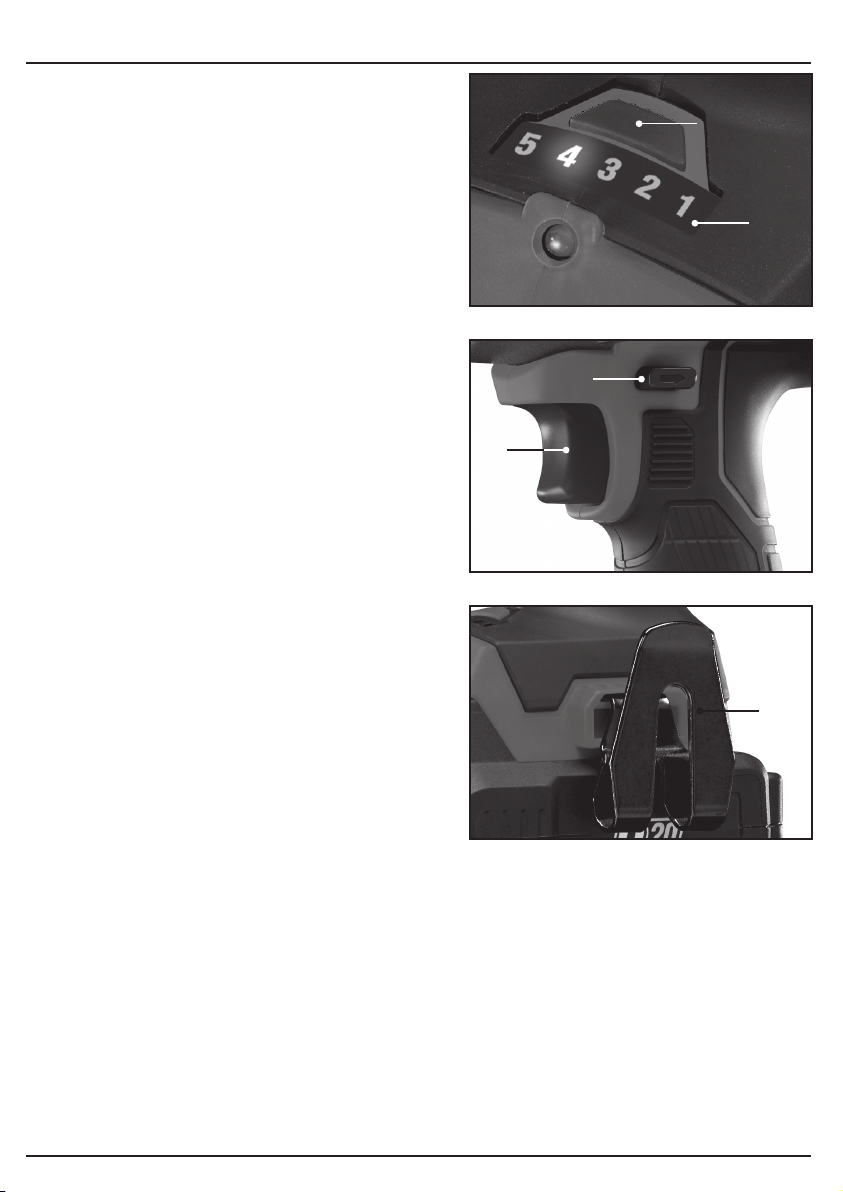
9.3 VARIABLE TORQUE CONTROL
– FIG.6
The impact wrench has 5 pre-set torque settings,
ranging from high to low:
– Press the variable torque adjustment button
to select the required torque setting. Each
torque setting is indicated on the torque setting
display
.
– The display features 5 LED numbers that
illuminate incrementally from high torque to low
torque, each time the torque adjustment button
is pressed.
– High torque (circa 400Nm) – is No.5 on the left,
through to low torque, No.1 (circa 100Nm) – the
last on the right.
– The 3 lights between indicate the intermediate
torque settings.
9.4 VARIABLE SPEED TRIGGER
– FIG. 7
When the trigger
is depressed, the drive will
rotate (provided the direction switch
is set in
the forward or reverse position). The rotational
speed varies with the torque adjustment.
This trigger switch is electronic which enables the
user to vary the speed continuously.
– The speed varies according to how far the
trigger switch is depressed.
– The further it is depressed, the faster the drive
spindle will rotate.
– The lighter it is depressed, the slower it will
rotate.
Note:
It may be necessary to initially release fixings
with a hand tool prior to using the impact wrench.
Note:
Always tighten fixings to the correct torque
as indicated by the manufacturer using a calibrated
torque wrench. Failure to do so may result in the
fixing becoming damaged or insufficiently
tightened.
Note:
This product is equipped with an electric brake.
9.5 BELT CLIP – FIG. 8
The spring steel belt clip
is convenient for hanging the drill temporarily. The clip can be
installed on either side of the tool.
To install the clip:
– Locate the clip
in position and fasten with screw supplied, take care to not over-tighten and
strip the thread.
- 17 -
FIG.6
FIG.7
FIG.8
Loading ...
Loading ...
Loading ...