OWNER'S MANUAL
MODELNO.271470
13.5HP38INCH
LAWNTRACTOR
• Assembly
• Operation
• Maintenance
• Service and Adjustments
• Troubleshooting
• Repair Parts
ForPartsandService, contactourauthorizeddistributor:
call1-800-849-1297 ForTechnicalAssistance:call1-800-829-5986
Poulcln
177110 11.15.00 RH
PRINTED IN U.S.A.
Safety Rules ......................................... 2
Product Specifications .......................... 5
Assembly .............................................. 7
Operation ............................................ 10
Maintenance Schedule ...................... 16
Maintenance....................................... 16
Service and Adjustments ....................20
Storage ............................................... 25
Troubleshooting ................................. 26
Repair Parts........................................ 30
Warranty ............................................. 46
IMPORTANT: This cutting machine is capable of amputating hands and feet and
throwing ob ects. Failure to observe the following safety instructions could result in
serious injury or death.
I. GENERAL OPERATION
• Read, understand, and follow all
instructions in the manual and on the
machine before starting.
• Only allow responsible adults, who are
familiar with the instructions, to operate
the machine.
• Clear the area of objects such as
rocks, toys, wire, etc., which could be
picked up and thrown by the blade.
• Be sure the area is clear of other
people before mowing. Stop machine
if anyone enters the area.
• Never carry passengers.
• Do not mow in reverse unless abso-
lutely necessary, Always look down
and behind before and while backing.
• Be aware of the mower discharge
direction and do not point it at anyone.
Do not operate the mower without
either the entire grass catcher or the
guard in place.
• Slow down before turning.
• Never leave a running machine
unattended. Always turn off blades, set
parking brake, stop engine, and
remove keys before dismounting.
• Turn off blades when not mowing.
• Stop engine before removing grass
catcher or unclogging chute.
• Mow only in daylight or good artificial
light.
• DO not operate the machine while
under the influence of alcohol or drugs.
• Watch for traffic when operating near or
crossing roadways.
• Use extra care when loading or
unloading the machine into a trailer or
truck.
• Data indicates that operators, age 60
years and above, are involved in a
large percentage of riding mower-
related injuries. These operators
should evaluate their ability to operate
the riding mower safely enough to
protect themselves and others from
serious injury.
II. SLOPE OPERATION
Slopes are a major factor related to loss-of-
control and tipover accidents, which can
result in severe injury or death. All slopes
require extra caution. Ifyou cannot back up
the slope or if you feel uneasy on it, do not
mow it.
DO:
• Mow up and down slopes, not across.
• Remove obstacles such as rocks, tree
limbs, etc.
• Watch for holes, ruts, or bumps.
Uneven terrain could overturn the
machine. Tall grass can hide obstacles.
• Use slow speed. Choose a low gear
so that you will not have to stop or shift
while on the slope.
• Follow the manufacturer's recommen-
dations for wheel weights or counter-
weights to improve stability.
• Use extra care with grass catchers or
other attachments. These can change
the stability of the machine.
• Keep all movement on the slopes slow
and gradual Do not make sudden
changes in speed or direction.
• Avoid starting or stopping on a slope. If
tires lose traction, disengage the
blades and proceed slowly straight
down the slope.
DO NOT:
• Do not turn on slopes unless neces-
sary, and then, turn slowly and gradu-
ally downhill, if possible.
• Do not mow near drep-offs, ditches, or
embankments. The mower could
suddenly turn over if a wheel is over
the edge of a cliff or ditch, or if an edge
caves in.
• Do not mow on wet grass. Reduced
traction could cause sliding.
• Do not try to stabilize the machine by
putting your foot on the ground.
IlLCHILDREN
Tragicaccidentscanoccuriftheoperator
isnotalert to the presence of children.
Children are often attracted to the
machine and the mowing activity. Never
assume that children win remain where
you last saw them.
• Keep children out of the mowing area
and under the watchful care of another
responsible adult.
• Be alert and turn machine off if children
enter the area.
• Before and when backing, look behind
and down for sma|l chi|dren.
• Never carry children. They may fall off
and be seriously injured or interfere
with safe machine operation.
• Never allow children to operate the
machine.
• Use extra care when approaching blind
corners, shrubs, trees, or other objects
that may obscure vision.
IV. SERVICE
• Use extra care in handling gasoline
and other fuels. They are flammable
and vapors are explosive.
- Use only an approved container.
- Never remove gas cap or add fue!
with the engine running. Allow
engine to cool before refueling, Do
not smoke.
- Never refuel the machine indoors,
- Never store the machine or fuel
container inside where there is an
open flame, such as a water heater.
• Never run a machine inside a closed
area.
• Keep nuts and bolts, especially blade
attachment bolts, tight and keep
equipment in good condition.
• Never tamper with safety devices.
Check their proper operation regularly.
• Keep machine free of grass, leaves, or
other debds build-up. Clean oil or fuel
spillage. Allow machine to cool before
storing.
• Stop and inspect the equipment if you
strike an object. Repair, if necessary,
before restarting.
• Never make adjustments or repairs
with the engine running,
• Grass catcher components are subject
to wear, damage, and detedoration,
which could expose moving parts or
atlow objects to be thrown. Frequently
check components and replace with
manufacturer's recommended pads,
when necessary.
• Mower blades are sharp and can cut.
Wrap the blade(s) or wear gloves, and
use extra caution when servicing them.
• Check brake operation frequently.
Adjust and service as required.
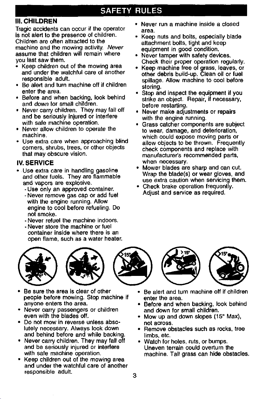
• Be sure the area is clear of other
people before mowing. Stop machine if
anyone enters the area.
• Never carry passengers or children
even with the blades off.
• Do not mow in reverse unless abso-
lutely necessary. Always look down
and behind before and while backing.
• Never carry children. They may fall off
and be seriously injured or interfere
with safe machine operation,
• Keep children out of the mowing area
and under the watchful care of another
responsible adult.
• Be alert and turn machine off if children
enter the area.
• Before and when backing, look behind
and down for small children.
• Mow up and down slopes (15 ° Max),
not across.
• Remove obstacles such as rocks, tree
limbs, etc.
• Watch for holes, ruts, or bumps.
Uneven terrain could overturn the
machine. Tall grass can hide obstacles.
3
• Use slow speed. Choose a low gear so
that you will not have to stop or shift
while on the slope.
• Avoid starting or stopping on a slope. If
tires lose traction, disengage the
blades and proceed slowly straight
down the slope.
• If machine stops while going uphill,
disengage blades, shift into reverse
and back down slowly.
• Do not turn on slopes unless neces-
sary, and then, turn slowly and gradu-
ally downhill, if possible.
_.Look for this symbol to point out
important safety precautions. It means
CAUTION!!! BECOME ALERT!!! YOUR
SAFETY IS INVOLVED.
_1_ CAUTION= In order to prevent
accidental starting when setting up,
transporting, adjusting or making repairs,
always disconnect spark plug wire and
place wire where it cannot contact spark
plug.
,_ CAUTION: Do not coast down a hill
in neutral, you may lose control of the
tractor.
_, CAUTION: Tow only the attachments
that are recommended by and comply
with specifications of the manufacturer of
your tractor. Use common sense when
towing. Operate only at the lowest
possible speed when on a slope. Too
heavy of a load, while on a slope, is
dangerous. Tires can lose traction with
the ground and cause you to lose control
of your tractor.
_I, WARNING: Engine exhaust, some of
its constituents, and certain vehicle
components contain or emit chemicals
known to the State of California to cause
cancer and birth defects or other repro-
ductive harm.
_,WARNING: Battery posts, terminals
and related accessories contain lead and
lead compounds, chemicals known to the
State of California to cause cancer and
birth defects or other reproductive harm.
Wash hands after handling.
4

PRODUCTSPECIFICATIONS
3ASOLINE 1.25 GALLONS
.3APACITY UNLEADED
_.NDTYPE: REGULAR
_ILTYPE SAE 30(ABOVE 32°F
_PI-SF/SJ): SAE 5W-30
(Below 32°F)
_)IL CAPACITY: 3 PTS
SPARK PLUG: CHAMPION
GAP: .030") RJt9LM
VALVE INTAKE: .005"-.007"
CLEARANCE: EXHAUST:.009"-.011"
GROUND SPEED FORWARD:
(MPH): 1ST 1.1
2ND 2.2
3RD 3.4
4TH 4.3
5TR 5.5
REVERSE: 1.7
TIRE FRONT: 14 PSI
)RESBURE: REAR: 12 PSI
3HARGING 3 AMPS BATTERY
3YSTEM: 5 AMPS HEADLIGHTS
3ATTERY: AMP/HR: 25
MIN. CCA: 190
CASE SIZE:U1 R
BLADE BOLT 27-35 FT. LBS
TORQUE:
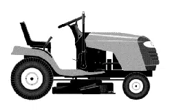
CONGRATULATIONS on your purchase
of a new tractor. It has been designed,
engineered and manufactured to give
you the best possible dependability and
performance.
Should you experience any problem you
cannot easity remedy, please contact
your nearest authorized service center.
We have competent, well-trained
technicians and the proper tools to
service or repair this tractor.
Please read and retain this manual. The
instructions will enable you to assemble
and maintain your tractor properly.
Always observe the "SAFETY RULES".
CUSTOMER RESPONSIBILITIES
• Read and observe the safety rules.
• Follow a regular schedule in maintain-
ing, caring for and using your tractor.
• Follow the instructions under =Mainte-
nance" and "Storage" sections of this
owner's manual.
,_WARNING: This tractor is equipped
with an internal combustion engine and
should not be used on or near any
unimproved forest-covered, brush-
covered or grass-covered land unless
the engine's exhaust system is equipped
with a spark arrester meeting applicable
local or state laws (if any). If a spark
arrester is used, it should be maintained
in effective working order by the opera-
tor.
In the state of California the above is
required bylaw (Section 4442 of the
California Public Resources Code).
Other states may have similar laws.
Federal laws apply on federal lands. A
spark arrester for the muffler is available
through your nearest authorized service
center/Department (See REPAIR PARTS
section of this manual).
5
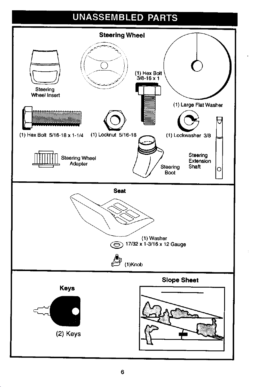
SteeringWheel
Steering
Wheel Insert
(1) HexBo_t
3/8-16 x 1
(1) Large Flat Washer
(1) Hex Bolt 5/16-18 x 1-1/4 (1) Locknut 5/16-18_ (1) Lockwasher 3/8
)"_-----_ / Steering
Illlllllll Steering Wheel / ] /" Extension
=_ Adapter / / / Steering Shaft
Boot
Seat
Keys
(2) Keys
(1) Washer
17/32 x 1-3/16 x 12 Gauge
_(1)Knob
Slope Sheet
Your new tractor has been assembled at the factory with exception of those parts left
unassembled for shipping purposes• To ensure safe and proper operation of your
tractor all parts and hardware you assemble must be tightened securely. Use the
correct tools as necessary to insure proper tightness• Review the video cassette before
you begin.
TOOLS REQUIRED FOR
ASSEMBLY
A socketwrenchset will makeassembly
easier. Standardwrenchsizes youneed
are listed below.
(1) 9/16"wrench (1) Pliers
(2) 1/2"wrench (1) Utilityknife
(1) Tire pressuregauge
When rightor left hand is mentionedin
thismanual,itmeans,from yourpointof
view,when you are in the operating
position(seated behindthe steering
wheel).
TO REMOVETRACTOR FROM
CARTON
• Remove all accessiblelooseparts
and partscartonsfrom carton.
• Cul, fromtopto bottom, along lineson
all four cornersof carton,and lay
panelsflat.
• Checkfor any additionalloose parts
orcartonsand remove.
BEFORE REMOVINGTRACTOR
FROM SKID
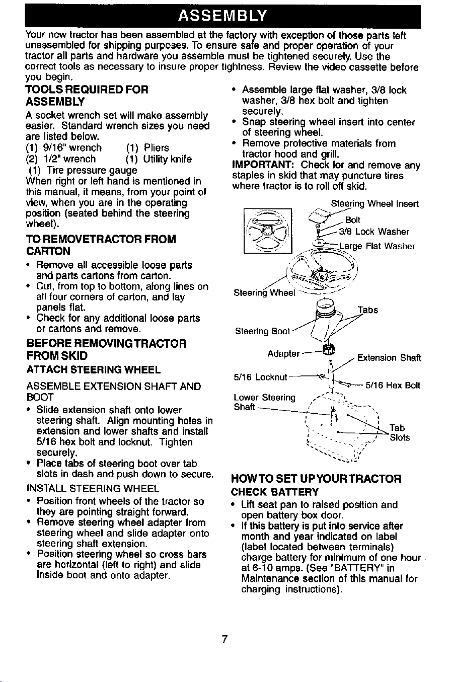
ATTACH STEERING WHEEL
ASSEMBLE EXTENSION SHAFT AND
BOOT
• Slide extension shaft onto lower
steering shaft. Align mounting holes in
extension and lower shafts and install
5/16 hex bolt and Iocknut. Tighten
securely.
• Place tabs of steering boot over tab
slots in dash and push down to secure.
INSTALL STEERING WHEEL
• Position front wheels of the tractor so
they are pointing straight forward,
• Remove steering wheel adapter from
steering wheel and slide adapter onto
steering shaft extension•
• Position steering wheel so cross bars
are horizontal (left to right) and slide
inside boot and onto adapter•
• Assemble large flat washer, 3/8 lock
washer, 3/8 hex bolt and tighten
securely.
• Snap steering wheel insert into center
of steering wheel.
• Remove protective materials from
tractor hood and grill•
IMPORTANT: Check for and remove any
staples in skid that may puncture tires
where tractor is to roll off skid.
SteeringWheel insert
o,t
";._ '--TJ-_Large Flat Washer
Steering Wheel _-_---
abs
Stae,ngBoot" L/'F
Adapter_
_//Extension Shaft
5/16 Lockr'_t_ L
IJ_--._ 5/16 Rex Bolt
Lower Steering ._- ,_,
Shaft_ , ,._ __ ,
_ " -_ , , Slots
HOWTO SET UPYOURTRACTOR
CHECK BATTERY
• Lift seat pan to raised position and
open battery box door.
• if this ba_.teryis put into sewice after
month and year indicated on label
(label located between terminals)
charge battery for minimum of one hour
at 6-10 amps. (See "BATTERY in
Maintenance section of this manual for
charging instructions).
Battery Box Label
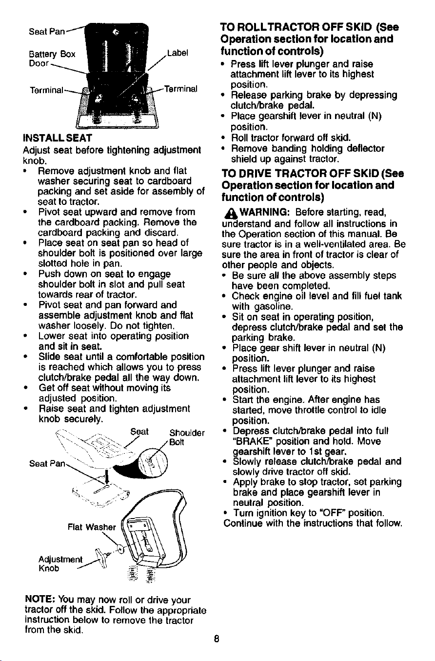
INSTALL SEAT
Adjust seat before tightening adjustment
knob.
Remove adjustment knob and flat
washer securing seat to cardboard
packing and set aside for assembly of
seat to tractor•
Pivot seat upward and remove from
the cardboard packing• Remove the
cardboard packing and discard.
• Place seat on seat pan so head of
shoulder bolt is positioned over large
slotted hole in pan.
• Push down on seat to engage
shoulder bolt in slot and pull seat
towards rear of tractor.
Pivot seat and pan forward and
assemble adjustment knob and flat
washer loosely. Do not tighten•
• Lower seat into operating position
and sit in seat.
• Slide seat until a comfortable position
is reached which allows you to press
clutch/brake pedal all the way down.
• Get off seat without moving its
adjusted position.
Raise seat and tighten adjustment
knob securely.
- -- Seat Shoulder
Seat Pan_ _ •
Flat Washer
TO ROLLTRACTOR OFF SKID (See
Operation section for location and
function of controls)
• Press lift lever plunger and raise
attachment lift lever to its highest
position.
• Release parking brake by depressing
clutch/brake pedal.
• Place gearshift lever in neutral (N)
position.
• Roll tractor forward off skid.
• Remove banding holding deflector
shield up against tractor.
TO DRIVE TRACTOR OFF SKID (See
Operation section for location and
function of controls)
_kWARNING: Before starting, read,
understand and follow all instructions in
the Operation section of this manual. Be
sure tractor is in a well-ventilated area. Be
sure the area in front of tractor is clear of
other people and objects.
• Be sure all the above assembly steps
have been completed.
• Check engine oil level and fill fuel tank
with gasoline.
• Sit on seat in operating position,
depress clutch/brake pedal and set the
parking brake.
• Place gear shift lever in neutral (N)
position.
• Press lift lever plunger and raise
attachment lift lever to its highest
position.
• Start the engine. After engine has
started, move throttle control to idle
position.
• Depress clutch/brake pedal into full
"BRAKE" position and hold. Move
gearshift lever to 1st gear.
• Slowly release clutch/brake pedal and
slowly drive tractor off skid.
• Apply brake to stop tractor, set parking
brake and place gearshift lever in
neutral position.
• Turn ignition key to "OFF" position.
Continue with the instructions that follow.
Adjustment
Knob
NOTE: You may now roll or drive your
tractor off the skid. Follow the appropriate
instruction below to remove the tractor
from the skid.
CHECKTIREPRESSURE
Thetiresonyourtractorwereoverin-
flatedatthefactoryfor shipping pur-
poses. Correct tire pressure is important
for best cutting performance.
• Reduce tire pressure to PSi shown in
"PRODUCT SPECIFICATIONS"
section of this manual.
CHECK FOR PROPER POSITION
OF ALL BELTS
See the figures that are shown for
replacing motion and mower blade drive
belts in the Service and Adjustments
section of this manual. Verify that the
belts are routed correctly.
CHECK DECK LEVELNESS
For best cutting results, mower housing
should be properly leveled. See "TO
LEVEL MOWER HOUSING" in the
Service and Adjustments section of this
manual.
CHECK BRAKE SYSTEM
After you learn how to operate your
tractor, check to see that the brake is
properly adjusted, See "TO ADJUST
BRAKE" in the Service and Adjustments
section of this manual.
,/CHECKLIST
BEFORE YOU OPERATE AND ENJOY
YOUR NEW TRACTOR, WE WISH TO
ASSURETHATYOU RECEIVETHE BEST
PERFORMANCE AND SATISFACTION
FROM THIS QUALITY PRODUCT.
PLEASE REVIEWTHE FOLLOWING
CHECKLIST:
,/All assembly instructions have been
completed.
4 No remaining loose parts in carton.
,/Battery is properly prepared and
charged. (Minimum 1 hour at 6 amps).
,/Seat is adjusted comfortably and
tightened securely.
,/All tires are properly inflated. (For
shipping purposes, the tires were
overinflated at the factory).
,/Be sure mower deck is properly leveled
side-to-side/front-to-rear for best cutting
results. (Tires must be properly inflated
for leveling).
,/Check mower and drive belts. Be sure
they are routed properly around pulleys
and inside all belt keepers.
#" Check wiring. See that all connections
are still secure and wires are properly
clamped.
WHILE LEARNING HOWTO USE YOUR
TRACTOR, PAY EXTRA ATTENTION TO
THE FOLLOWING IMPORTANT ITEMS:
4" Engine oil is at proper level.
,/Fuel tank is filled with fresh, clean,
regular unleaded gasoline.
,/Become familiar with all controls - their
location and function. Operate them
before you start the engine.
,/Be sure brake system is in safe
operating condition.
9
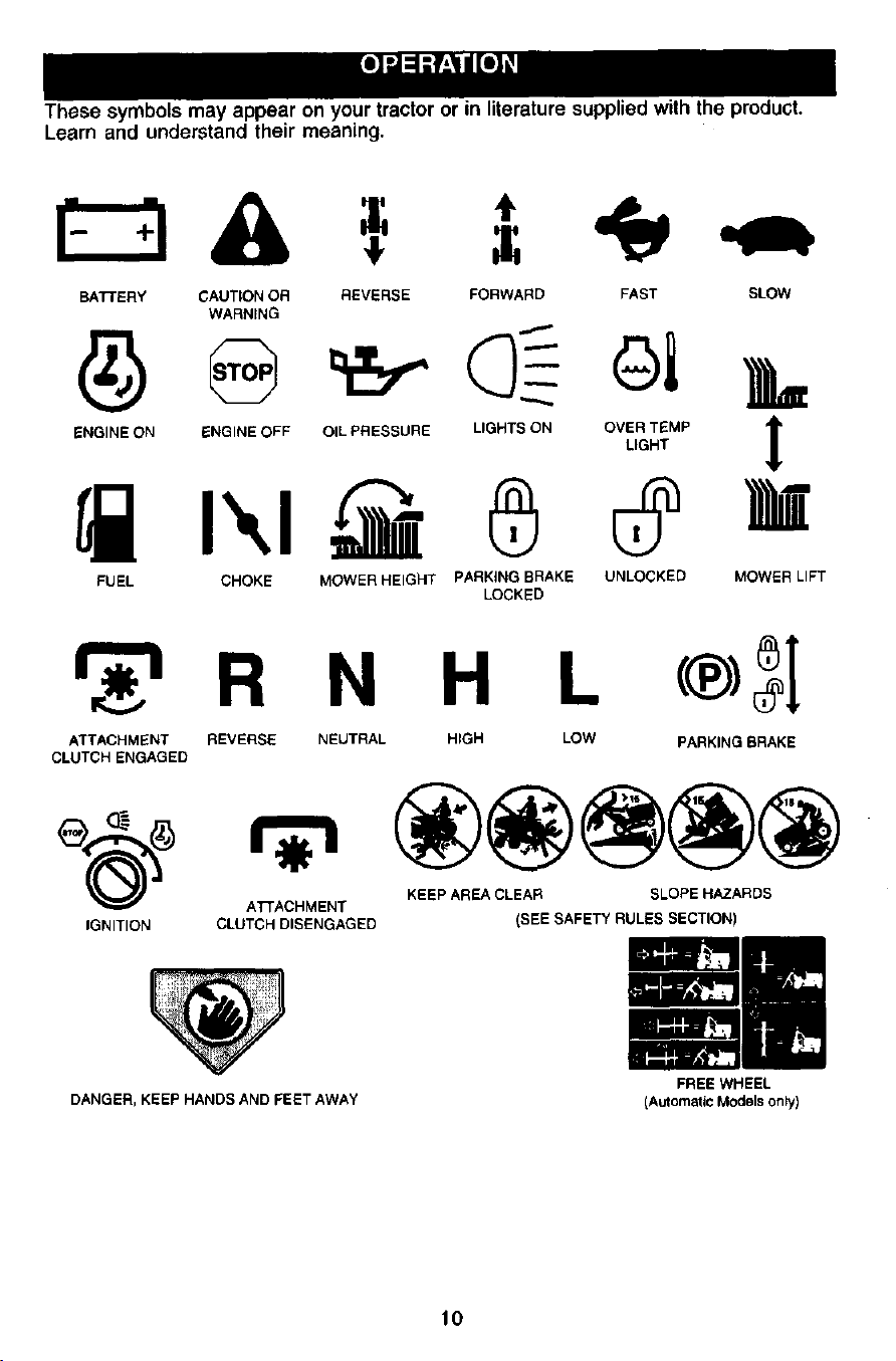
These symbols may appear on your tractor or in literature supplied with the product.
Learn and understand their meaning.
BATTERY CAUTION OR REVERSE FORWARD FAST SLOW
WARNING
SNG,NEON_NO,NEOFFO,LPRESSUREL,GRTSGNOV_,_MP_
FUEL CHOKE MOWER HEIGHT PARKING BRAKE UNLOCKED MOWER LIFT
LOCKED
_ R N H L <®_[
ATTACHMENT REVERSE NEUTRAL HIGH LOW PARKING BRAKE
CLUTCH ENGAGED
KEEP AREA CLEAR SLOPE HAZARDS
ATTACHMENT
IGNITION CLUTCH DISENGAGED (SEE SAFETY RULES SECTION)
DANGER, KEEP HANDS AND FEET AWAY
10
FREE WHEEL
(AutomaticModels only)
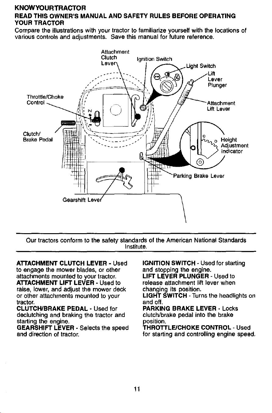
KNOWYOURTRACTOR
READ THIS OWNER'S MANUAL AND SAFETY RULES BEFORE OPERATING
YOUR TRACTOR
Compare the illustrations with your tractor to familiarize yourself with the locations of
various controls and adjustments. Save this manual for future reference.
Attachment
Clutch Ignition Switch
ht Switch
Throttle/Choke
Control
Lever
Plunger
Lift Lever
Clutch/
Brake Pedal
Height
Adjustment
Indicator
Ig Brake Lever
\
Our tractors conform to the safety standards of the American National Standards
Institute,
ATTACHMENT CLUTCH LEVER - Used
to engage the mower blades, or other
attachments mounted to your tractor.
ATTACHMENT LIFT LEVER - Used to
raise, lower, and adjust the mower deck
or other attachments mounted to your
tractor.
CLUTCH/BRAKE PEDAL - Used for
declutching and braking the tractor and
starting the engine.
GEARSHIFT LEVER - Selects the speed
and direction of tractor.
IGNITION SWITCH - Used for starting
and stopping the engine.
LIFT LEVER PLUNGER - Used to
release attachment lift lever when
changing its position.
LIGHT SWITCH - Turns the headlights on
and off.
PARKING BRAKE LEVER - Locks
clutch/brake pedal into the brake
position.
THROTTLE/CHOKE CONTROL - Used
for starting and controlling engine speed.
11
The operation of any tractor can result in foreign objects thrown into the
eyes, which can result in severe eye damage. Always wear safety
glasses or eye shields while operating your tractor or performing any
adjustments or repairs. We recommend a wide vision safety mask over
spectacles or standard safety glasses.
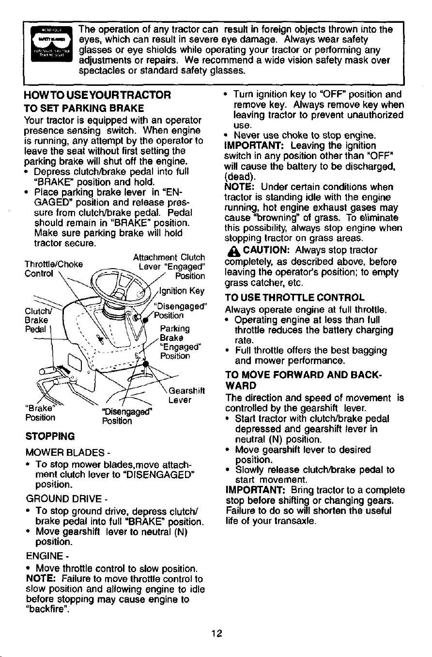
HOWTO USEYOURTRACTOR
TO SET PARKING BRAKE
Your tractor is equipped with an operator
presence sensing switch. When engine
is running, any attempt by the operator to
leave the seat without first setting the
parking brake will shut off the engine.
• Depress clutch/brake pedal into full
"BRAKE" position and hold.
• Place parking brake lever in "EN-
GAGED" position and release pres-
sure from clutch/brake pedal. Pedal
should remain in "BRAKE" position.
Make sure parking brake will hold
tractor secure.
A_achment Clu_h
Throttle/Choke Lever"Engaged"
Control \ Position
Brake
"Br_
Posilion
"Disengaged'
Position
/IgnitionKey
Parking
_Engaged"
Position
arshift
Lever
STOPPING
MOWER BLADES -
• To stop mower blades,move attach-
ment clutch lever to "DISENGAGED"
position.
GROUND DRIVE -
• To stop ground drive, depress clutch/
brake pedal into full "BRAKE" position.
• Move gearshift lever to neutral (N)
position.
ENGINE -
• Move throttle control to slow position.
NOTE: Failure to move throttle control to
slow position and allowing engine to idle
before stopping may cause engine to
"backfire".
• Turn ignition key to "OFF" position and
remove key. Always remove key when
leaving tractor to prevent unauthorized
use.
• Never use choke to stop engine.
IMPORTANT: Leaving the ignition
switch in any position other than "OFF"
will cause the battery to be discharged,
(dead).
NOTE: Under certain conditions when
tractor is standing idle with the engine
running, hot engine exhaust gases may
cause "browning" of grass. To eliminate
this possibility, always stop engine when
stopping tractor on grass areas.
CAUTION: Always stop tractor
completely, as described above, before
leaving the operator's position; to empty
grass catcher, etc.
TO USE THROTTLE CONTROL
Always operate engine at full throttle.
• Operating engine at less than full
throttle reduces the battery charging
rate.
• Full throttle offers the best bagging
and mower performance.
TO MOVE FORWARD AND BACK-
WARD
The direction and speed of movement is
controlled by the gearshift lever.
• Start tractor with clutch/brake pedal
depressed and gearshift lever in
neutral (N) position.
• Move gearshift lever to desired
position.
• Slowly release clutch/brake pedal to
start movement.
IMPORTANT: Bring tractor to a complete
stop before shifting or changing gears.
Failure to do so will shorten the useful
life of your transaxle.
12
TO ADJUST MOWER CUTTING HEIGHT
The position of the attachment lift lever
determines the cutting height.
• Grasp lift!ever.
• Press plunger with thumb and move
lever to desired position.
The cutting height range is approxi-
mately 1-1/2 to 4". The heights are
measured from the ground to the blade
tip with the engine not running. These
heights are approximate and may vary
depending upon soil conditions, height of
grass and types of grass being mowed.
• The average lawn should be cut to
approximately 2-1/2 inches during the
cool season and to over 3 inches
during hot months. For healthier and
better looking lawns, mow often and
after moderate growth.
• For best cutting performance, grass
over 6 inches in height should be
mowed twice. Make the first cut
relatively high; the second to desired
height.
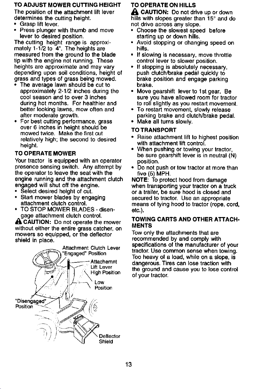
TO OPERATE MOWER
Your tractor is equipped with an operator
presence sensing switch. Any attempt by
the operator to !eave the seat with the
engine running and the attachment c!utch
engaged will shut off the engine.
• Select desired height of cut.
• Start mower blades by engaging
attachment c!utch control.
• TO STOP MOWER BLADES - disen-
gage attachment clutch control.
CAUTION: Do not operate the mower
without either the entire grass catcher, on
mowers so equipped, or the deflector
shield in place.
AttachmentClutch Lever
"Engaged" Position
Lift Lever
High Position
Low
Position
TO OPERATE ON HILLS
_i CAUTION: Do not drive up or down
hi!Is with slopes greater than 15° and do
not drive across any slope.
• Choose the slowest speed before
starting up or down hills.
• Avoid stopping or changing speed on
hi!!s.
• If s!owing is necessary, move throttle
control lever to slower position.
• If stopping is absolutely necessary,
push c_utch/brake pedal quickly to
brake position and engage parking
brake.
• Move gearshift lever to 1st gear. Be
sure you have allowed room for tractor
to roll slightly as you restart movement.
• To restart movement, slowly release
parking brake and clutch/brake pedal.
• Make all turns slowly.
TO TRANSPORT
• Raise attachment lift to highest position
with attachment lift control.
• When pushing or towing your tractor,
be sure gearshift lever is in neutral (N)
position.
• Do not push or tow tractor at more than
five (5) MPH.
NOTE: To protect hood from damage
when transporting your tractor on a truck
or a trailer, be sure hood is closed and
secured to tractor. Use an appropriate
means of tying hood to tractor (rope, cord,
etc.).
TOWING CARTS AND OTHER ATTACH-
MENTS
Tow only the attachments that are
recommended by and comply with
specifications of the manufacturer of your
tractor. Use common sense when towing.
Too heavy of a load, while on a slope, is
dangerous. Tires can lose traction with
the ground and cause you to lose control
of your tractor.
/
Shield
13
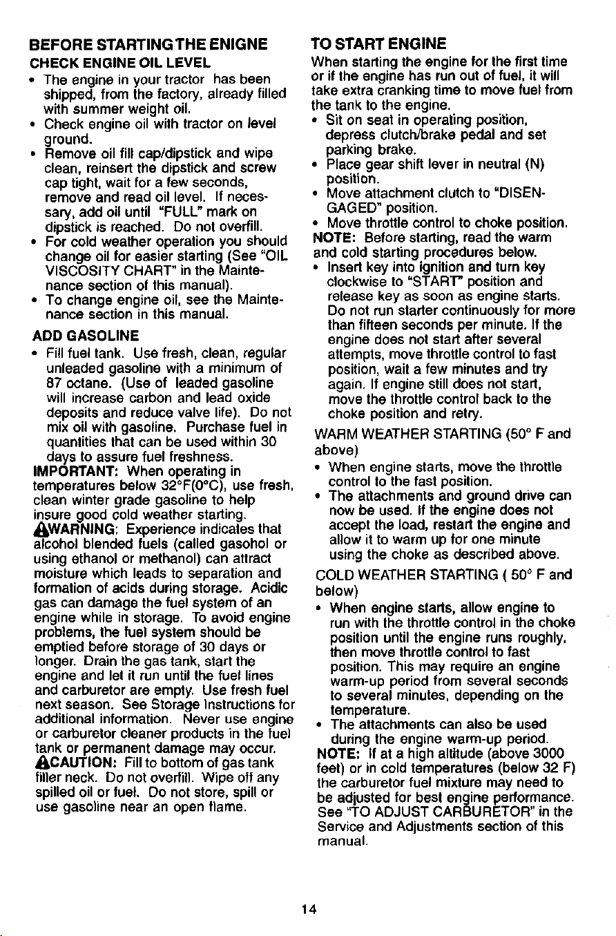
BEFORE STARTINGTHE ENIGNE
CHECK ENGINE OIL LEVEL
• The engine in your tractor has been
shipped, from the factory, already filled
with summer weight oil.
• Check engine oil with tractor on level
ground.
• Remove oil fill cap/dipstick and wipe
clean, reinsert the dipstick and screw
cap tight, wait for a few seconds,
remove and read oil level. If neces-
sary, add oil until "FULL" mark on
dipstick is reached. Do not overfill.
• For cold weather operation you should
change oil for easier starting (See "OIL
VISCOSITY CHART" in the Mainte-
nance section of this manual).
• To change engine oil, see the Mainte-
nance section in this manual.
ADD GASOLINE
• Fill fuel tank. Use fresh, clean, regular
unleaded gasoline with a minimum of
87 octane. (Use of leaded gasoline
will increase carbon and lead oxide
deposits and reduce valve life). Do not
mix oil with gasoline. Purchase fuel in
quantities that can be used within 30
days to assure fuel freshness.
IMPORTANT: When operating in
temperatures below 32°F(0°C), use fresh,
clean winter grade gasoline to help
insure good cold weather starting.
_WARNING; Experience indicates that
alcohol blended fuels (called gasohol or
using ethanol or methanol) can attract
moisture which leads to separation and
formation of acids during storage. Acidic
gas can damage the fuel system of an
engine while in storage. To avoid engine
problems, the fuel system should be
emptied before storage of 30 days or
longer. Drain the gas tank, start the
engine and let it run until the fuel lines
and carburetor are empty. Use fresh fuel
next season. See Storage Instructions for
additional information. Never use engine
or carburetor cleaner products in the fuel
tank or permanent damage may occur.
_,CAUTION: Fillto bottom of gas tank
filler neck. Do not overfill. Wipe off any
spilled oil or fuel Do not store, spill or
use gasoline near an open flame.
TO START ENGINE
When starting the engine for the first time
or ifthe engine has run out of fuel, it will
take extra cranking time to move fuel from
the tank to the engine.
• Sit on seat in operating position,
depress clutch/brake pedal and set
parking brake.
• Place gear shift lever in neutral (N)
position.
• Move attachment clutch to "DISEN-
GAGED" position.
• Move throttle control to choke position.
NOTE: Before starting, read the warm
and cold starting procedures below.
• Insert key into ignition and turn key
clockwise to "START" position and
retease key as soon as engine starts.
Do not run starter continuously for more
than fifteen seconds per minute. If the
engine does not start after several
attempts, move throttle control to fast
position, wait a few minutes and try
again. If engine still does not start,
move the throttle control back to the
choke position and retry.
WARM WEATHER STARTING (50 ° F and
above)
• When engine starts, move the throttle
control to the fast position.
• The attachments and ground drive can
now be used. If the engine does not
accept the load, restart the engine and
allow it to warm up for one minute
using the choke as described above.
COLD WEATHER STARTING ( 50° F and
below)
• When engine starts, allow engine to
run with the throttle control in the choke
position until the engine runs roughly,
then move throttle control to fast
position. This may require an engine
warm-up period from several seconds
to several minutes, depending on the
temperature.
• The attachments can also be used
dudng the engine warm-up period.
NOTE: if at a high altitude (above 3000
feet) or in cold temperatures (below 32 F)
the carburetor fuel mixture may need to
be adjusted for best engine performance.
See "TO ADJUST CARBURETOR" in the
Service and Adjustments section of this
manual.
14
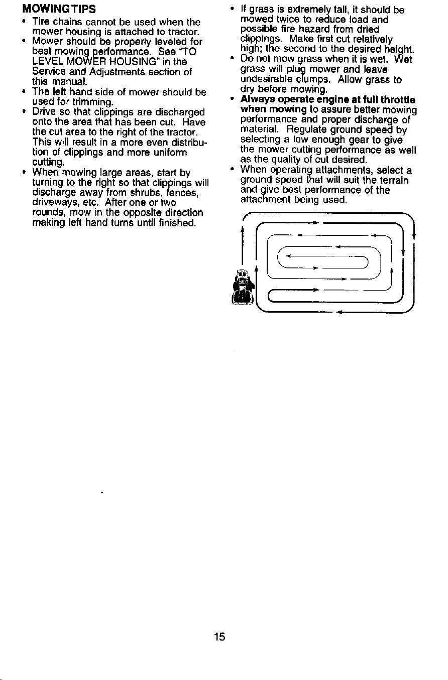
MOWINGTIPS
• Tirechainscannotbeusedwhenthe
mowerhousingisattachedtotractor.
• Mowershouldbeproperlyleveledfor
bestmowingperformance.See"TO
LEVELMOWER HOUSING" in the
Service and Adjustments section of
this manual.
• The left hand side of mower should be
used for trimming.
• Drive so that clippings are discharged
onto the area that has been cut. Have
the cut area to the right of the tractor.
This will result in a more even distribu-
tion of clippings and more uniform
cutting.
• When mowing large areas, start by
turning to the right so that clippings will
discharge away from shrubs, fences,
driveways, etc. After one or two
rounds, mow in the opposite direction
making left hand turns until finished.
• If grass is extremely tall, it should be
mowed twice to reduce load and
possible fire hazard from dried
clippings. Make first cut relatively
high; the second to the desired height.
• Do not mow grass when it is wet. Wet
grass will plug mower and leave
undesirable clumps. Allow grass to
dry before mowing.
• Always operate engine at full throttle
when mowing to assure better mowing
performance and proper discharge of
material. Regulate ground speed by
selecting a low enough gear to give
the mower cutting performance as well
as the quality of cut desired.
• When operatingattachments, select a
ground speed that will suit the terrain
and give best performance of the
attachment being used.
15
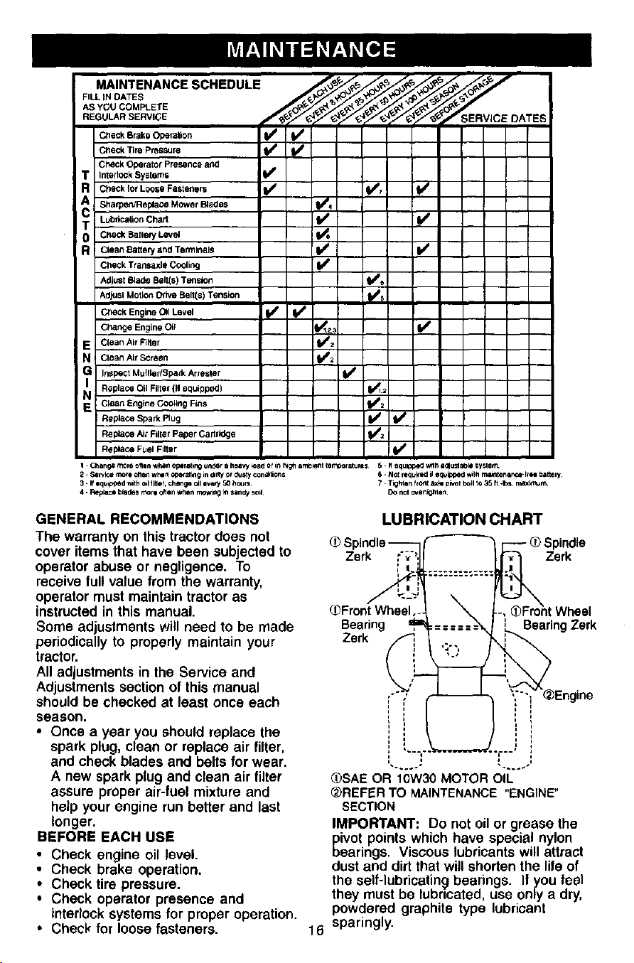
MAINTENANCESCHEDULE
FILL IN CATES
AS YOU COMPLETE
REGULAR SERVICE
Check Brake Operalton __-k Tire P_re
Cl_ck Operator Presence and
InterlOCkSystems J_
CheCk for Loose Fasteners jJ/ (1_7 lI_
Shatpe_eplace Mower Blades 11_4
Ledncat_on Chart II/ I_
CheCk Ballery Leve_ _ I
Clean Battery and Terminals I_ Jl_ I
Check Ttansaxle Cooling ll_
AdjuSt Blade Belt(e) Tension ll_
AdjuSl Motion Drive Belt(s) Tension Jl_
Check Engine (_1 Level _ IJ_
C;_ange Engine Olt I_lz,
i/
Clean Air Filter _2
Clean Air Screen kS2
InsPect Muffler/Spa_k Armsler I_
Replace Oil Filter {11equipped) J_)_
Clean Engine Cooling Fins _2
Replace Spark Plug I1_ fl_
Beplace Ak F,lte r Paper Cartmldge tS'z
Replace Fuel Filter
1. Changa more ellen l_n oper_ing under a heaW 4Dador in I_gh ar_ot q)rr_ratum$ 5. Mequipped Wlh a_uSlaOkl Syslem.
2. Sewk:e more ellen w_ln oper_klg in dlrly or dusty con_lions 6. N¢_ re_t_ked _ eq_l_oed w_tl m&_enlr_e-I_ee bakery
3-1foqu_pedV, lthodll,ef, changeoflever_5Ohours 7 Tig_tenfrontaxkepr_olbOlltO3Stl.bs r_xk_Jr_
4. Reptsce blades rl",OrI often when rl_,lng _nsanay sod DO not ov_nx3r4en
GENERAL RECOMMENDATIONS
The warranty on this tractor does not
cover items that have been subjected to
operator abuse or negligence. To
receive full value from the warranty,
operator must maintain tractor as
instructed in this manual.
Some adjustments will need to be made
periodically to properly maintain your
tractor.
All adjustments in the Service and
Adjustments section of this manual
should be checked at least once each
season.
• Once a year you should replace the
spark plug, clean or replace air filter,
and check blades and belts for wear.
A new spark plug and clean air filter
assure proper air-fuel mixture and
help your engine run better and last
longer.
BEFORE EACH USE
• Check engine oil level.
• Check brake operation.
• Check tire pressure.
• Check operator presence and
interlock systems for proper operation.
• Check for loose fasteners.
LUBRICATION CHART
Zerk Zerk
_Front Wheel
Searing Searing Zerk
Zerk
(ibSAE OR 10W30 MOTOR OIL
_)REFER TO MAINTENANCE"ENGINE"
SECTION
IMPORTANT: Do not oil or grease the
pivot points which have special nylon
bearings. Viscous lubricants will attract
dust and dirt that will shorten the life of
the self-lubricating bearings. If you feel
they must be lubricated, use only a dry,
powdered graphite type lubricant
16 sparingly.
TRACTOR
Always observe safety rules when
performing any maintenance.
BRAKE OPERATION
If tractor requires more than six (6) feet
stopping distance at high speed in
highest gear, then brake must be ad-
justed. (See "TO ADJUST BRAKE" in the
Service and Adjustments section of this
manual).
TIRES
• Maintain proper air pressure in all tires
(See "PRODUCT SPECIFICATIONS"
section of this manual).
• Keep tires free of gasoline, oil, or insect
control chemicals which can harm
rubber.
• Avoid stumps, stones, deep ruts, sharp
objects and other hazards that may
cause tire damage.
NOTE: To seal tire punctures and prevent
flat tires due to slow leaks, tire sealant
may be purchased from your local parts
dealer, Tire sealant also prevents tire dry
rot and corrosion,
OPERATOR PRESENCE SYSTEM
Be sure operator presence and interlock
systems are working properly, If your
tractor does not function as described,
repair the problem immediately.
• The engine should not start unless the
clutch/brake pedal is fully depressed
and attachement clutch control is in the
disengaged position.
• When the engine is running, any
attempt by the operator to leave the
seat without first setting the parking
brake should shut off the engine.
• When the engine is running and the
attachment clutch is engaged, any
attempt by the operator to leave the
seat should shut off the engine.
• The attachment clutch should never
operate unless the operator is in the
seat.
BLADE CARE
For best results mower blades must be
kept sharp. Replace bent or damaged
blades.
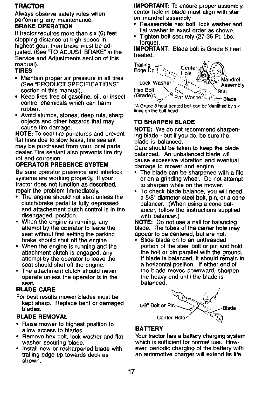
BLADE REMOVAL
• Raise mower to highest position to
allow access to blades.
• Remove hex bolt, lock washer and flat
washer securing blade,
• Install new or resharpened blade with
trailing edge up towards deck as
shown.
IMPORTANT: To ensure proper assembly,
center hole in blade must align with star
on mandrel assembly.
• Reassemble hex bolt, lock washer and
flat washer in exact order as shown.
• Tighten bolt securely (27-35 Ft. Lbs.
torque).
IMPORTANT: Blade bolt is Grade 8 heat
treated.
Trailing .....p., _S_
Ed e U . ._ Center_p_ \\
g P L.5.'_... _ _._H°le _,_'_::_._
"_ "_ _-- Mandre
LockWasher "" ._._j_-_;X_ j Assembly
Hex Bolt __ _ ._,_ \o*
(Grade) ._ Flat Washer_.-_--- Blade
"A Grade 8 heat treated bolt can be identified by six
lines on the bolt head.
TO SHARPEN BLADE
NOTE: We do not recommend sharpen-
ing blade - but if you do, be sure the
blade is balanced.
Care should be taken to keep the blade
balanced. An unbalanced blade will
cause excessive vibration and eventual
damage to mower and engine.
• The blade can be sharpened with a file
or on a grinding wheel. Do not attempt
to sharpen while on the mower.
• To check blade balance, you will need
a 5/8" diameter steel bolt, pin, or a cone
balancer. (When using a cone bal-
ancer, follow the instructions supplied
with balancer.)
NOTE: Do not use a nail for balancing
blade. The lobes of the center hole may
appear to be centered, but are not.
• Slide blade on to an unthreaded
portion of the steel bolt or pin and hold
the bolt or pin parallel with the ground.
If blade is balanced, it should remain in
a horizontal position. If either end of
the blade moves downward, sharpen
the heavy end until the blade is
balanced.
. / f
5/8" Boltor P "''_%/_'_"_" _/"/ _ .,_=.. Blade
CenterHole/ •!"_._
BATTERY
Your tractor has a battery charging system
which is sufficient for normal use. How-
ever, periodic charging of the battery with
an automotive charger will extend its life.
17
• Keep battery and terminals clean.
• Keep battery bolts tight.
• Keep small vent holes open.
• Recharge at 6-10 amperes for 1 hour.
NOTE: The original equipment battery on
your tractor is maintenance free. Do not
attempt to open or remove caps or covers.
Adding or checking level of electrolyte is
not necessary.
TO CLEAN BATTERY AND TERMINALS
Corrosion and dirt on the battery and
terminals can cause the battery to "leak"
power.
• Open battery box door.
• Disconnect BLACK battery cable first
then RED battery cable and remove
battery from tractor.
• Rinse the battery with plain water and
dry.
• Clean terminals and battery cable ends
with wire brush until bright.
• Coat terminals with grease or petro-
leum jelly.
• Reinstall battery (See "REPLACING
BATTERY" in the SERVICE AND
ADJUSTMENTS section of this
manual).
V-BELTS
Check V-belts for deterioration and wear
after 100 hours of operation and replace
if necessary. The belts are not adjustable.
Replace belts if they begin to slip from
wear.
TRANSAXLE COOLING
Keep transaxle free from build-up of dirt
and chaff which can restrict cooling.
ENGINE
LUBRICATION
Only use high quality detergent oil rated
with API service classification SF, or SJ.
Select the oil's SAE viscosity grade
according to your expected operating
temperature.
NOTE: Although multi-viecosity oils
(5W30, lOW30 etc.) improve starting in
cold weather, these multi-viscosity oils
will result in increased oil consumption
when used above 32°F. Check your
engine oil level more frequently to avoid
possible engine damage from running
low on oil
Change the oil after every 25 hours of
operation or at least once a year if the
tractor is not used for 25 hours in one
year.
Check the crankcase oil level before
starting the engine and after each eight
(8) hours of operation. Tighten oil fill cap/
dipstick securely each time you check the
oil level.
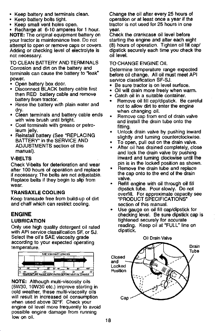
TO CHANGE ENGINE OIL
Determine temperature range expected
before oil change. All oil must meet API
service classification SF-SJ.
• Be sure tractor is on level surface.
• Oil will drain more freely when warm.
• Catch oil in a suitable container.
Remove oil fill cap/dipstick. Be careful
not to allow dirt to enter the engine
when changing oil.
Remove cap from end of drain valve
and install the drain tube onto the
fitting.
• Unlock drain valve by pushing inward
slightly and turning counterclockwise.
• To open, pull out on the drain valve.
• After oil has drained completely, close
and lock the drain valve by pushing
inward and turning clockwise until the
pin is in the locked position as shown.
• Remove the drain tube and replace
the cap onto to the end of the drain
valve.
Refill engine with oil through oil fill
dipstick tube. Pour slowly. Do not
overfill. For approximate capacity see
"PRODUCT SPECIFICATIONS"
section of this manual.
Use gauge on oil fill cap/dipstick for
checking level. Be sure dipstick cap is
tightened securely for accurate
reading. Keep oil at =FULL" line on
dipstick.
Oil Drain Valve
Drain
[ _ "_ Tubs
C,oeed /
and _-'-_'-_ ]_ J _V"
Locked _ _ _ ,_
Position _
Cap J
18
CLEAN AIR SCREEN
Air screen must be kept free of dirt and
chaff to prevent engine damage from
overheating. Clean with a wire brush or
compressed air to remove dirt and
stubborn dried gum fibers.
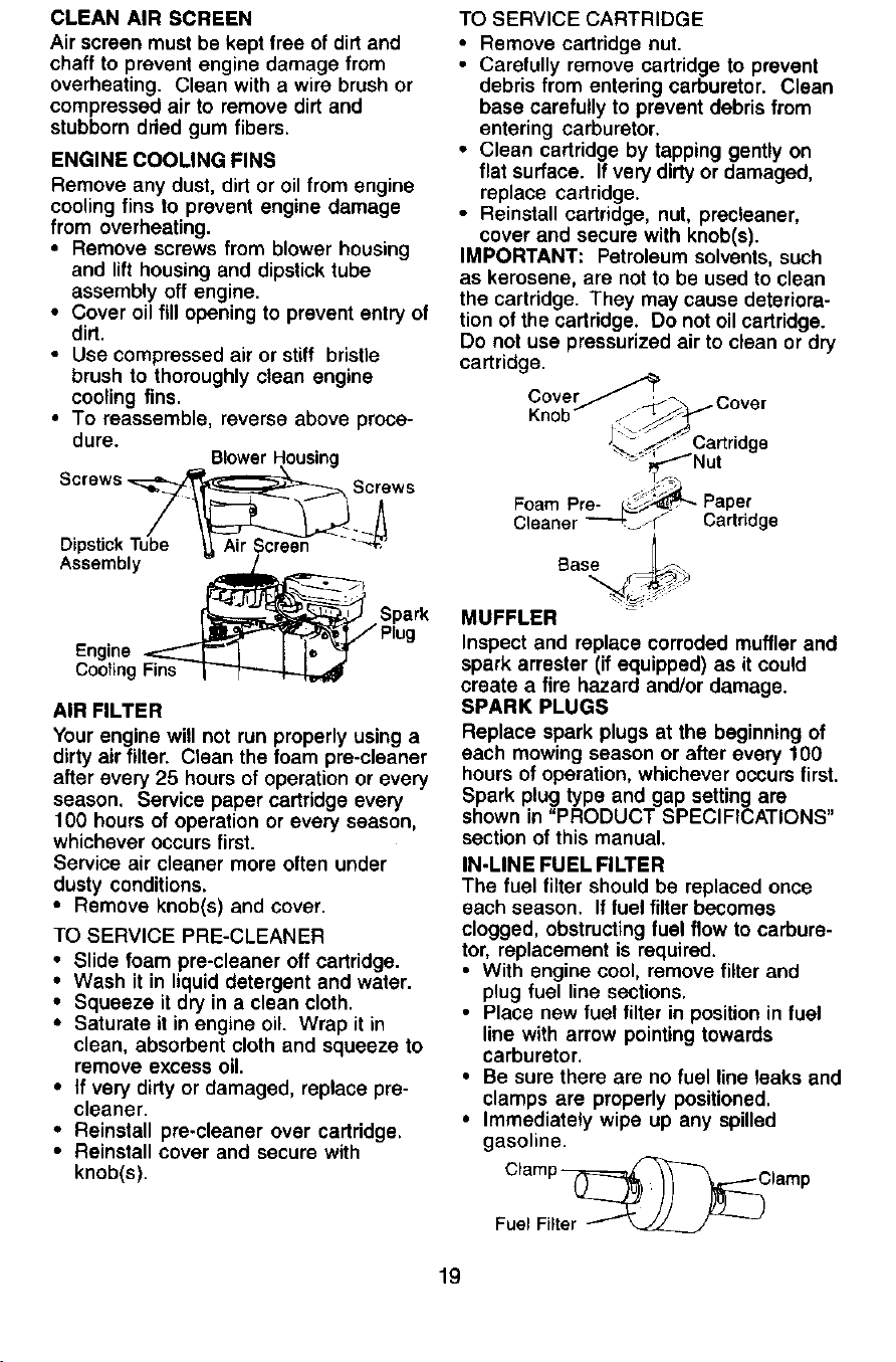
ENGINE COOLING FINS
Remove any dust, dirt or oil from engine
cooling fins to prevent engine damage
from overheating.
• Remove screws from blower housing
and lift housing and dipstick tube
assembly off engine.
• Cover oil fill opening to prevent entry of
dirt.
• Use compressed air or stiff bristle
brush to thoroughly clean engine
cooling fins.
• To reassemble, reverse above proce-
dure.
BlowerHousing
Screws -, Screws
DipstickTube
Assembly
Spark
Engine
Cooling Fins
AIR FILTER
Your engine will not run properly using a
dirty air filter. Clean the foam pre-cleaner
after every 25 hours of operation or every
season. Service paper cartridge every
100 hours of operation or every season,
whichever occurs first.
Service air cleaner more often under
dusty conditions.
• Remove knob(s) and cover.
TO SERVICE PRE-CLEANER
• Slide foam pre-cleaner off cartridge.
• Wash it in liquid detergent and water.
• Squeeze it dry in a clean cloth.
• Saturate it in engine oil. Wrap it in
clean, absorbent cloth and squeeze to
remove excess oil.
• If very dirty or damaged, replace pre-
cleaner.
• Reinstall pre-cleaner over cartridge.
• Reinstall cover and secure with
knob(s).
TO SERVICE CARTRIDGE
• Remove cartridge nut.
• Carefully remove cartridge to prevent
debris from entering carburetor. Clean
base carefully to prevent debris from
entering carburetor.
• Clean cartridge by tapping gently on
flat surface. If very dirty or damaged,
replace cartridge.
• Reinstall cartridge, nut, precleaner,
cover and secure with knob(s).
IMPORTANT: Petroleum solvents, such
as kerosene, are not to be used to clean
the cartridge. They may cause deteriora-
tion of the cartridge. Do not oil cartridge.
Do not use pressurized air to clean or dry
cartridge.
C°ver/"_P _Cover
Knob
Cartridge
_._ Nut
Foam Pr_ Paper
Cleaner . zrj Cartridge
Base _-.
MUFFLER
Inspect and replace corroded muffler and
spark arrester (if equipped) as it could
create a fire hazard and/or damage.
SPARK PLUGS
Replace spark plugs at the beginning of
each mowing season or after every 100
hours of operation, whichever occurs first.
Spark plug type and gap setting are
shown in "PRODUCT SPECIFICATIONS"
section of this manual.
IN-LINE FUEL FILTER
The fuel filter should be replaced once
each season. If fuel filter becomes
clogged, obstructing fuel flow to carbure-
tor, replacement is required.
• With engine cool, remove filter and
plug fuel line sections.
• Place new fuel filter in position in fuel
line with arrow pointing towards
carburetor.
• Be sure there are no fuel line leaks and
clamps are properly positioned.
• Immediately wipe up any spilled
gasoline.
19
CLEANING
i Clean engine, battery, seat, finish, etc.
of a_lforeign matter.
Keep finished surfaces and wheels free
of all gasoline, oil, stc.
• Protect painted surfaces with automo-
tive type wax.
We do not recommend using a garden
hose to clean your tractor unless the
electrical system, muffler, air filter and
carburetor are covered to keep water out.
Water in engine can result in a short-
ened engine life.
CAUTION: Before performing any service or adjustments:
• Depress clutch/brake pedal fully and set parking brake.
• Place gearshift lever in neutral (N) position.
• Place attachment clutch in =DISENGAGED" position.
i urn ignition key "OFF" and remove key.
Make sure the blades and all moving parts have completely stopped.
Disconnect spark plug wire from spark plug and place wire where it cannot
come in contact with plug.
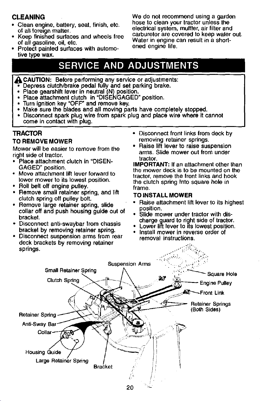
TRACTOR
TO REMOVE MOWER
Mower will be easier to remove from the
rightside of tractor.
• Place attachment clutch in "DISEN-
GAGED" position.
• Move attachment lift lever forward to
lower mower to its lowest position.
• Roll belt off engine pulley.
• Remove small retainer spring, and lift
clutch spring off pulley bolt.
• Remove large retainer spring, slide
collar off and push housing guide out of
bracket.
• Disconnect anti-swaybar from chassis
bracket by removing retainer spring.
• Disconnect suspension arms from rear
deck brackets by removing retainer
springs.
Small Retainer Spring
C_utch Sp_
• Disconnect front links from deck by
removing retainer springs.
• Raise lift lever to raise suspension
arms. Slide mower out from under
tractor.
IMPORTANT: If an attachment other than
the mower deck is to be mounted on the
tractor, remove the front links and hook
the clutch spring Into square hole in
frame.
TO INSTALL MOWER
• Raise attachment lift lever to its highest
position.
• Slide mower under tractor with dis-
charge guard to right side of tractor.
• Lower lift lever to its lowest position.
• Install mower in reverse order of
removal instructions.
SuspensionArms . ' ...,, , -
_';t' _ Square Hole
Link
Retainer Springs
(Both Sides)
Retainer Spdn
Anti-Sway
HousingGuide
LargeRetainerSpring Bra/ke t
jl
20 _'_
TO LEVEL MOWER HOUSING
Adjust the mower while tractor is parked
on level ground or driveway. Make sure
tires are properly inflated (See "PROD-
UCT SPECIFICATIONS" section of this
manual). If tires are over or
underinflated, you will not properly adjust
your mower.
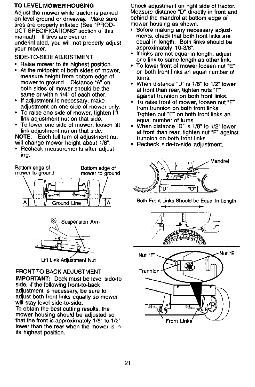
SIDE-TO-SIDE ADJUSTMENT
• Raise mower to its highest position.
• At the midpoint of both sides of mower,
measure height from bottom edge of
mower to ground. Distance"A" on
both sides of mower should be the
same or within 1/4" of each other.
• If adjustment is necessary, make
adjustment on one side of mower only.
• To raise one side of mower, tighten lift
link adjustment nut on that side.
• To lower one side of mower, loosen tiff
link adjustment nut on that side.
NOTE: Each full turn of adjustment nut
will change mower height about 1/8".
• Recheck measurements after adjust-
ing.
Bottomedgeof Bottomedgeof
mower toground mower toground
Check adjustment on right side of tractor.
Measure distance "D" directly in front and
behind the mandrel at bottom edge of
mower housing as shown.
• Before making any necessary adjust-
ments, check that both front links are
equal in length. Both links should be
approximately 10-3/8".
• If links are not equal in length, adjust
one link to same length as other link.
• To lower front of mower loosen nut "E"
on both front links an equal number of
turns.
• When distance "D" is 1/8" to 1/2" lower
at front than rear, tighten nuts "F"
against trunnion on both front links.
• To raise front of mower, loosen nut "P
from trunnion on both front links.
Tighten nut "E" on both front links an
equal number of turns.
• When distance "D" is 1/8" to I/2" lower
at front than rear, tighten nut "F" against
trunnion on both front links.
• Recheck side-to-side adjustment.
o_,\_ - o oot /" Mandrel
Both Front LinksShouldbe Equalin Length
Suspension Arm
FRONT-TO-BACK ADJUSTMENT
IMPORTANT: Deck must be level side-to
side. If the following front-to-back
adjustment is necessary, be sure to
adjust both front links equally so mower
will stay level side-to-side.
To obtain the best cutting results, the
mower housing should be adjusted so
that the front is approximately 1/8" to 1/2"
lower than the rear when the mower is in
its highest position.
Nut
Front
21
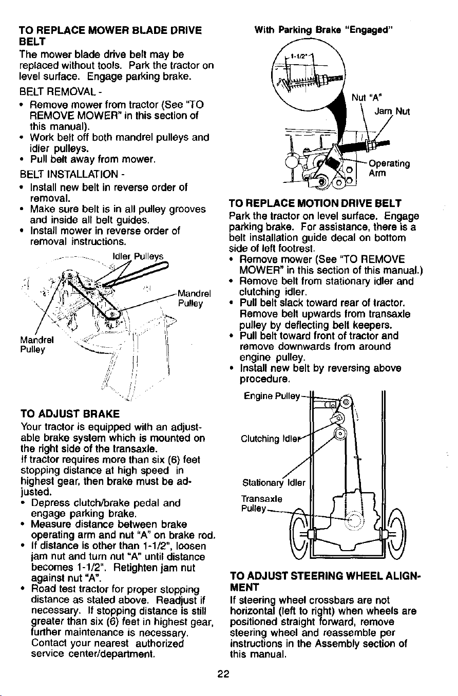
TO REPLACE MOWER BLADE DRIVE
BELT
The mower blade drive belt may be
replaced without tools. Park the tractor on
level surface. Engage parking brake.
BELT REMOVAL -
• Remove mower from tractor (See "TO
REMOVE MOWER" in this section of
this manual).
• Work belt off both mandrel pulleys and
idler pulleys.
• Pull belt away from mower.
BELT INSTALLATION -
• Install new belt in reverse order of
removal.
• Make sure belt is in all pulley grooves
and inside all belt guides.
• Install mower in reverse order of
removal instructions.
Pulley
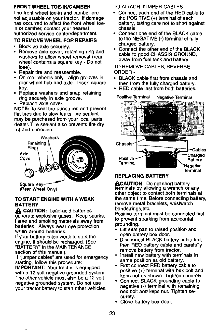
TO ADJUST BRAKE
Your tractor is equipped with an adjust-
able brake system which is mounted on
the right side of the transaxle.
if tractor requires more than six (6) feet
stopping distance at high speed in
highest gear, then brake must be ad-
justed.
• Depress clutch/brake pedal and
engage parking brake.
• Measure distance between brake
operating arm and nut "A" on brake red.
• If distance is other than 1-1/2", loosen
jam nut and turn nut "A" until distance
becomes 1-1/2". Retighten jam nut
against nut "A".
• Road test tractor for proper stopping
distance as stated above. Readjust if
necessary. If stopping distance is still
greater than six (6) feet in highest gear,
further maintenance is necessary.
Contact your nearest authorized
service center/department.
With Parking Brake "Engaged"
Nut "A"
_ _OrPerat'ng
TO REPLACE MOTION DRIVE BELT
Park the tractor on level surface. Engage
parking brake. For assistance, there is a
belt installation guide decal on bottom
side of left footrest.
• Remove mower (See "TO REMOVE
MOWER" in this section of this manual.)
• Remove belt from stationary idler and
clutching idler.
• Pull belt slack toward rear of tractor.
Remove belt upwards from transaxle
pulley by deflecting belt keepers.
• Pull belt toward front of tractor and
remove downwards from around
engine pulley.
• Install new belt by reversing above
procedure.
Clutching
StationaryIdler
Traneaxle
TO ADJUST STEERING WHEEL ALIGN-
MENT
If steering wheel crossbars are not
horizontal (left to right) when wheels are
positioned straight forward, remove
steering wheel and reassemble per
instructions in the Assembly section of
this manual.
22
FRONTWHEELTOE-IN/CAMBER
Thefrontwheeltoe-inandcamberare
notadjustableonyourtractor.Ifdamage
hasoccurredtoaffectthefront wheel toe-
in or camber, contact your nearest
authorized service center/department.
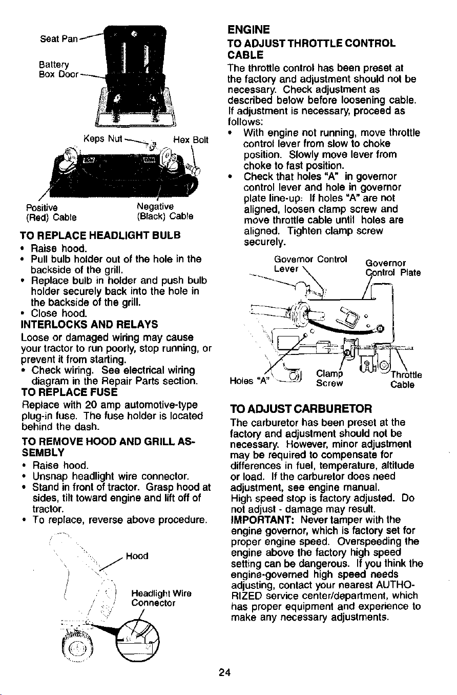
TO REMOVE WHEEL FOR REPAIRS
• Block up axle securely.
• Remove axle cover, retaining ring and
washers to allow wheel removal (rear
wheel contains a square key - Do not
lose).
• Repair tire and reassemble.
• On rear wheels only: align grooves in
rear wheel hub and axle. Insed square
key.
• Replace washers and snap retaining
ring securely in axle groove.
• Replace axle cover.
NOTE: To seal tire punctures and prevent
flat tires due to slow leaks, tire sealant
may be pumhased from your local parts
dealer. Tire sealant also prevents tire dry
rot and corrosion.
Washers
Retaining
Ring
Axle
Cover
TO START ENGINE WITH A WEAK
BATTERY
CAUTION: Lead-acid batteries
generate explosive gases. Keep sparks,
flame and smoking materials away from
batteries. Always wear eye protection
when around batteries.
If your battery is too weak to start the
engine, it should be recharged. (See
"BATTERY" in the MAINTENANCE
section of this manual).
If =jumper cables" are used for emergency
starting, follow this procedure:
IMPORTANT: Your tractor is equipped
with a 12 volt negative grounded system.
The other vehicle must also be a 12 volt
negative grounded system. Do not use
your tractor battery to start other vehicles.
TO ATTACH JUMPER CABLES -
• Connect each end of the RED cable to
the POSITIVE (+) terminal of each
battery, taking care not to short against
chassis.
• Connect one end of the BLACK cable
to the NEGATIVE (-) terminal of fully
charged battery.
• Connect the other end of the BLACK
cable to good CHASSIS GROUND,
away from fuel tank and battery.
TO REMOVE CABLES, REVERSE
ORDER -
• BLACK cable first from chassis and
then from the fully charged battery.
• RED cable last from both batteries.
Positive Terminal Negative Terminal
Terminal Battery
Negative
Terminal
REPLACING BATTERY
/kCAUTION: Do not short battery
terminals by allowing a wrencn or any
other object to contact both terminals at
the same time. Before connecting battery,
remove metal bracelets, wristwatch
bands,rings,etc.
Positive terminal must be connected first
to prevent sparking from accidental
grounding.
• Lift seat pan to raised position and
open battery box door.
• Disconnect BLACK battery cable first
then RED battery cable and carefully
remove battery from tractor.
• Install new battery with terminals in
same position as old battery.
• First connect RED battery cable to
positive (+) terminal with hex bolt and
keps nut as shown. Tighten securely.
• Connect BLACK grounding cable to
negative (-) terminal with remaining
hex bolt and keps nut. Tighten se-
curely.
• Close battery box door.
23
Battery
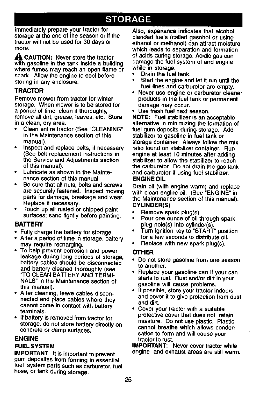
Keps Nut _ ,1 Hex Bolt
Positive Negative
(Red) Cable (Black) Cable
TO REPLACE HEADLIGHT BULB
• Raise hood.
• Pull bulb holder out of the hole in the
backside of the grill.
• Replace bulb in holder and push bulb
holder securely back into the hole in
the backside of the grill.
• Close hood.
INTERLOCKS AND RELAYS
Loose or damaged wiring may cause
your tractor to run poorly, stop running, or
prevent it from starting.
• Check wiring. See electrical wiring
diagram in the Repair Parts section.
TO REPLACE FUSE
Replace with 20 amp automotive-type
plug-in fuse. The fuse holder is located
behind the dash.
TO REMOVE HOOD AND GRILL AS-
SEMBLY
• Raise hood.
• Unsnap headlight wire connector.
• Stand in front of tractor. Grasp hood at
sides, tilt toward engine and liftoff of
tractor.
• To replace, reverse above procedure.
•_ _. Hood
') HeadlightWire
/ ÷ _ Connector
ENGINE
TOADJUST THROTTLE CONTROL
CABLE
The throttlecontrolhas been presetat
thefactoryand adjustmentshouldnot be
necessary. Checkadjustmentas
describedbelow beforelooseningcable.
If adjustmentis necessary,proceedas
follows:
• With enginenot running,movethrottle
controllever fromslowto choke
position. Slowlymoveleverfrom
choketofast position.
• Checkthat holes"A" in governor
controllever and hole in governor
plate line-up: If holes"A" are not
aligned, loosenclamp screw and
movethrottlecable until holes are
aligned. Tightenclampscrew
securely.
Governor Control Governor
.... _ Lever _ Cpntrol Plate
Holes "A" _ Screw Cable
TO ADJUST CARBURETOR
The carburetor has been preset at the
factory and adjustment should not be
necessary. However, minor adjustment
may be required to compensate for
differences in fuel, temperature, altitude
or load. If the carburetor does need
adjustment, see engine manual.
High speed stop is factory adjusted. Do
not adjust - damage may result.
IMPORTANT: Never tamper with the
engine governor, which is factory set for
proper engine speed. Overspeeding the
engine above the factory high speed
setting can be dangerous. If you think the
engine-governed high speed needs
adjusting, contact your nearest AUTHO-
RIZED service center/department, which
has proper equipment and experience to
make any necessary adjustments.
24
immediatelyprepareyourtractorfor
storageattheendoftheseasonorifthe
tractorwillnotbeusedfor 30 days or
more.
CAUTION: Never store the tractor
with gasoline in the tank inside a building
where fumes may reach an open flame or
spark. Allow the engine to cool before
storing in any enclosure.
TRACTOR
Remove mower from tractor for winter
storage. When mower is to be stored for
a period of time, clean it thoroughly,
remove all dirt, grease, leaves, etc. Store
in a clean, dry area.
Clean entire tractor (Sea "CLEANING"
in the Maintenance section of this
manual).
Inspect and replace belts, if necessary
(See belt replacement instructions in
the Service and Adjustments section
of this manual).
• Lubricate as shown in the Mainte-
nance section of this manual.
• Be sure that all nuts, bolts and screws
are securely fastened. Inspect moving
parts for damage, breakage and wear.
Replace if necessary.
Touch up all rusted or chipped paint
surfaces; sand lightly before painting.
BATTERY
• Fully charge the battery for storage.
• After a period of time in storage, battery
may require recharging.
• To help prevent corrosion and power
leakage during long periods of storage,
battery cables should be disconnected
and battery cleaned thoroughly (see
"TO CLEAN BATTERY AND TERMI-
NALS" in the Maintenance section of
this manual).
• After cleaning, leave cables discon-
nected and place cables where they
cannot come in contact with battery
terminals.
• If battery is removed from tractor for
storage, do not store battery directly on
concrete or damp surfaces.
ENGINE
FUEL SYSTEM
IMPORTANT: It is important to prevent
gum deposites from forming in essential
fuel system parts such as carburetor, fuel
hose, or tank during storage.
Also, experiance indicates that alcohol
blended fuels (called gasohol or using
ethanol or methanol) can attract moisture
which leads to separation and formation
of acids during storage. Acidic gas can
damage the fuel system of and engine
while in storage.
• Drain the fuel tank.
• Start the engine and let it run until the
fuel lines and carburetor are empty.
• Never use engine or carburetor cleaner
products in the fuel tank or permanent
damage may occur.
• Use fresh fuel next season.
NOTE: Fuel stabilizer is an acceptable
alternative in minimizing the formation of
fuel gum deposits during storage. Add
stabilizer to gasoline in fuel tank or
storage container. Always follow the mix
ratio found on stabilizer container. Run
engine at least 10 minutes after adding
stabilizer to allow the stabilizer to reach
the carburetor. Do not drain the gas tank
and carburetor if using fuel stabilizer.
ENGINE OIL
Drain oil (with engine warm) and replace
with clean engine oil. (See "ENGINE" in
the Maintenance section of this manual).
CYLINDER(S)
• Remove spark plug(s).
• Pour one ounce of oil through spark
plug hole(s) into cylinder(s).
• Turn ignition key to "START" position
for a few seconds to distribute oi!.
• Replace with new spark plug(s).
OTHER
• Do not store gasoline from one season
to another.
• Replace your gasoline can if your can
starts to rust. Rust and/or dirt in your
gasoline will cause problems.
• If possible, store your tractor indoors
and cover it to give protection from dust
and dirt.
• Cover your tractor with a suitable
protective cover that does not retain
moisture. Do not use plastic. Plastic
cannot breathe which a,ows conden-
sation to form and will cause your
tractor to rust.
IMPORTANT: Never cover tractor while
engine and exhaust areas are still warm.
25
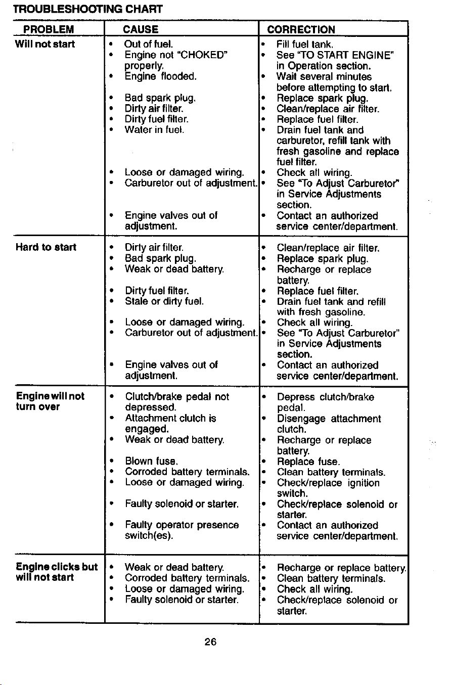
TROUBLESHOOTING CHART
PROBLEM
Will not start
Hard to start
Enginewill not
turn over
Engine clicks but
will not start
CAUSE
• Out offuel.
• Enginenot "CHOKED"
properly.
• Engine flooded.
• Bad spark plug. _=,
• Dirty air filter. I"
• Dirtyfuelfilter.
I,
• Water in fuel.
Loose or damaged wiring.
Carburetor out of adjustment
Enginevalvesoutof
adjustment.
• Dirty air filter,
• Bad spark plug.
• Weak or dead battery.
• Dirtyfuelfilter.
• Stale or dirty fuel.
Loose or damaged wiring.
Carburetor out of adjustment
Enginevalvesoutof
adjustment.
Clutch/brake pedal not
depressed.
Attachment clutch is
engaged.
Weak or dead battery.
Blown fuse.
Corroded battery terminals.
Loose or damaged wiring.
Faulty solenoid or starter.
Faulty operator presence
switch(es).
• Weak or deadbattery.
• Corrodedbatteryterminals,
• Loose or damagedwiring.
• Faultysolenoidor starter.
CORRECTION
Fill fuel tank.
• See "TO START ENGINE"
in Operation section.
• Wait several minutes
before attempting to start.
Replace spark plug,
Clean/replace air filter.
Replace fuel filter.
Drain fuel tank and
carburetor, refill tank with
fresh gasoline and replace
fuel filter,
Check all wiring.
See "To Adjust Carburetor"
in Service Adjustments
section,
Contact an authorized
service center/department.
Clean/replace air filter.
Replace spark plug.
Recharge or replace
battery.
Replace fuel filter,
Drain fuel tank and refill
with fresh gasoline.
Check all wiring.
See "To Adjust Carburetor"
in Service Adjustments
section.
Contact an authorized
service center/department.
Depress clutch/brake
pedal.
Disengage attachment
clutch.
Recharge or replace
battery.
Replace fuse.
Clean battery terminals.
Check/replace ignition
switch.
Check/replace solenoid or
starter.
Contact an authorized
service center/department.
Recharge or replace battery
Clean battery terminals.
Check all wiring.
Check/replace solenoid or
starter.
26
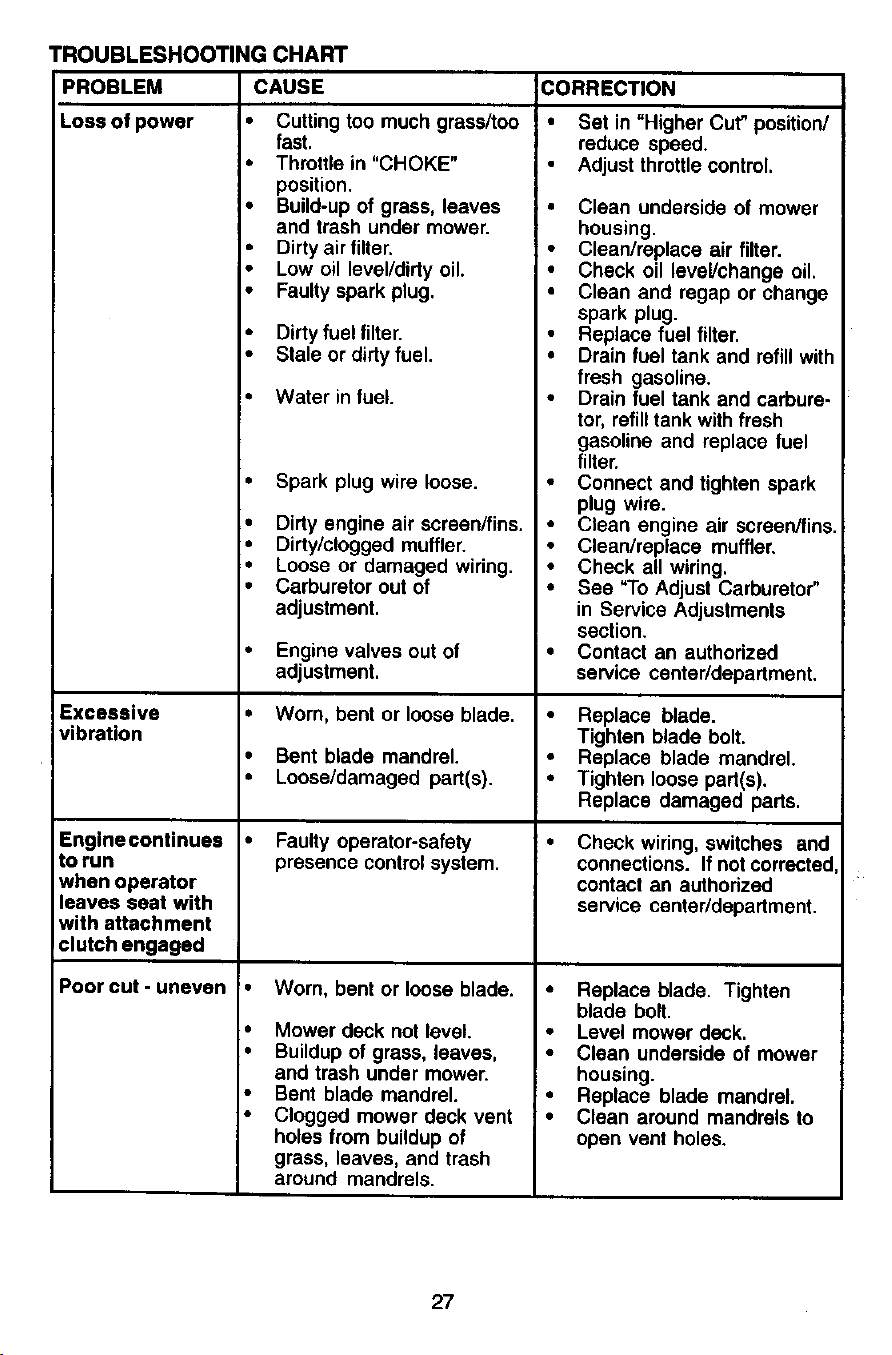
TROUBLESHOOTINGCHART
PROBLEM CAUSE CORRECTION
Lossofpower • Cuttingtoomuchgrassltoo
Excessive
vibration
fast.
• Throttle in"CHOKE"
position.
• Build-up of grass, leaves
and trash under mower.
• Dirtyair filter.
• Low oil level]dirty oil.
• Faulty spark plug.
Enginecontinues •
to run
when operator
leaves seat with
with attachment
clutch engaged
Poorcut-uneven
• Dirty fuel filter.
• Stale or dirty fuel.
• Water in fuel. •
• Spark plug wire loose.
• Dirty engine air scraen/fins. •
• Dirty/clogged muffler.
• Loose or damaged wiring. •
• Carburetor out of •
adjustment.
• Engine valves out of •
adjustment.
• Worn, bent or loose blade. •
• Bent blade mandrel.
• Loose/damaged part(s). •
Faulty operator-safety
presence control system.
Worn, bent or loose blade. •
Mower deck not level.
Buildup of grass, leaves, •
and trash under mower.
Bent blade mandrel.
Clogged mower deck vent •
holes from buildup of
grass, leaves, and trash
around mandrels.
• Set in "HigherCut"position/
reduce speed.
Adjustthrottlecontrol.
• Clean underside of mower
housing.
• Clean/replace air filter.
• Check oil level]change oil.
• Clean and regap or change
spark plug.
Replace fuel filter.
Drain fuel tank and refill with
fresh gasoline.
Drain fuel tank and carbure.
tor, refilltank with fresh
gasoline and replace fuel
filter.
Connect and tighten spark
plug wire.
Clean engine air screen/fins.
Clean/replace muffler.
Check all wiring.
See "To Adjust Carburetor"
in Service Adjustments
section.
Contact an authorized
service center/department.
Replace blade.
Tighten blade bolt.
Replace blade mandrel.
Tighten loose part(s).
Replace damaged pads.
Check wiring, switches and
connections. If not corrected
contact an authorized
service center/depadment.
Replace blade. Tighten
blade bolt.
Level mower deck.
Clean underside of mower
housing.
Replace blade mandrel.
Clean around mandrels to
open vent holes.
27
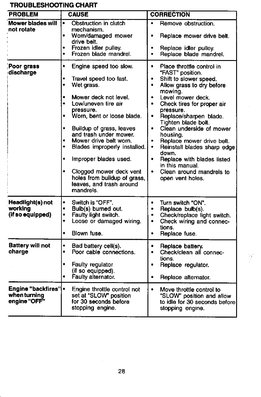
TROUBLESHOOTING CHART
PROBLEM CAUSE CORRECTION
_ower blades will • Obstruction in clutch Remove obstruction,
lot rotate mechanism.
• Worn/damaged mower Replace mower drive belt.
drive belt,
• Frozen idler pulley. Replace idler pulley,
• Frozen blade mandrel, Replace blade mandrel,
:_oor grass • Engine speed too slow.
:lischarge
-leadllght(e) not •
Norklng
',ifso equipped)
Battery will not •
;harge •
Travel speed too fast,
• Wet grass.
• Mower deck not level.
• Low/uneven tire air
pressure.
• Worn, bent or loose blade.
• Buildup of grass, leaves
and trash under mower.
Mower drive belt worn.
Blades improperly installed.
Improper blades used.
Clogged mower deck vent
holes from buildup of grass,
leaves, and trash around
mandrels.
Switch is "OFF".
Bulb(s) burned out.
Faulty light switch.
Loose or damaged wiring.
Blown fuse.
Bad battery cell(s).
Poor cable connections.
• Faulty regulator
(if so equipped).
• Faulty alternator.
Engine "backfires" •
Nhen turning
.=ngine"OFF"
Engine throttle control not
set at "SLOW" position
for 30 seconds before
stopping engine.
• Place throttle control in
"FAST" position.
• Shift to slower speed.
• Allow grass to dry before
mowing.
• Level mower deck.
• Check tires for proper air
pressure.
• Replace/sharpen blade.
Tighten blade bolt.
• Clean underside of mower
housing.
Replace mower drive belt.
• Reinstall blades sharp edge
down.
Replace with blades listed
in this manual.
• Clean around mandrels to
open vent holes.
• Turn switch "ON".
• Replace bulb(s).
Check/replace light switch.
• Check wiring and connec-
tions.
• Replace fuse.
• Replace battery.
• Check/clean all connec-
tions,
• Replace regulator.
• Replace alternator.
• Move throttle control to
"SLOW" position and allow
to idle for 30 seconds before
stopping engine.
28
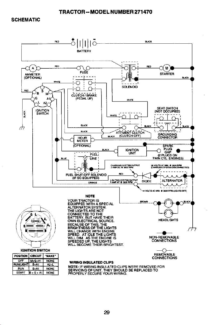
SCHEMATIC
TRACTOR -- MODEL NUMBER 271470
BATTERY
AMMETER
_(OPTIONAL)
IG AI(
IGNITION
SWITCH
IGNITION SWITCH
i I
FUSE ST TER
CLOTC-H_ BRA-KE
SEAT SWITCH
........ (NOT OCCUPIED)
W_ffE I I ;- ......... i
,_,
,_, J •
_ t
(OPTIONAL)
_( SPARK
8L_CX IGNITION GAP
•, -FOEL_ UNIT
J 12 PLUGS ON
=u_ I LINE ' TWI_ CYL. ENGINES)
b
i k CHAR_ SYSTEM OUTPUT 28 VOL_ AC _ g _ R_
3 A)4P _ Q _ R_M IC_FK,_G 8VST]EM r_TIED)
FUEL SHUT-OFF SOLENOID F_0 t _ _ _ d
(IF SO EQUIPPED) !-_T_ sysmu
OR_,_GE 5A_,_ e _ RPM L _r
NOTE
YOUR TRACTOR IS SR<_'_N _ _ _eUCK.
EQUIPPED WITH A SPECIAL
ALTERNATOR SYSTEM,
THE LIGHTS ARE NOT
CONNECTED TO THE
BATTERY, BUT HAVE THEIR
OWN ELECTRICAL SOURCE, HEADLIGHTS
BECAUSE OF THIS, THE
BRIGHTNESS OF THE LIGHTS /_
WILL CHANGE WITH ENGINE
SPEED. AT IDLE THE LIGHTS
WILL DiM, AS THE ENGINE IS NON-REMOVASLE
SPEEDED UP, THE LIGHTS CONNECTIONS
WILL BECOME THEIR BRIGHTEST,
REMOVABLE
CONNECTIONS
WIRING INSULATED CLIPS
NOTE: IF WIRING INSULATED CLIPS WERE REMOVED FOR
SERVICING OF UNIT, THEY SHOULD BE REPLACED TO
PROPERLY SECURE YOUR WIRING,
29
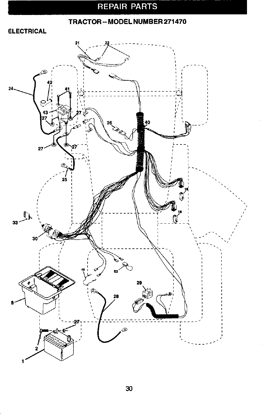
ELECTRICAL
TRACTOR-- MODEL NUMBER 271470
25
30
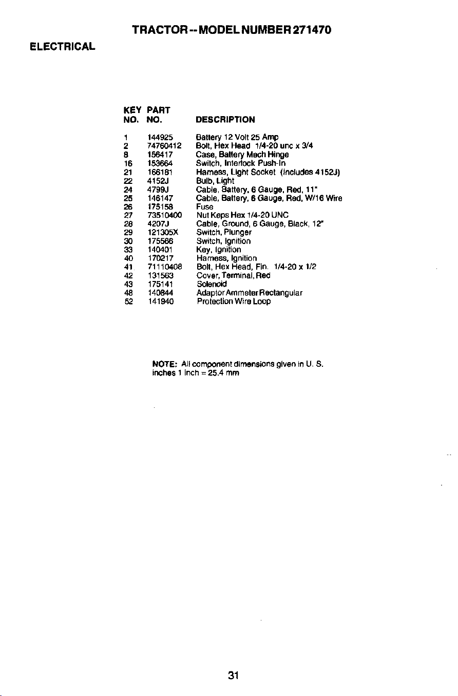
ELECTRICAL
TRACTOR -- MODEL NUMBER 271470
KEY PART
NO. NO. DESCRIPTION
1 144925 Battery 12 Volt 25 Amp
2 74760412 Bolt, Hex Head 1/4-20 unc x 3/4
8 156417 Case, Battery Moch Hinge
16 153664 Switch, Interlock Push-In
21 166181 Hamess, Light Socket (Includes 4152J)
22 4152J Bulb, Light
24 4799J Cable, Battery, 6 Gauge, Red, 11 •
25 146147 Cable, Battery, 6 Gauge, Red, W/16 Wire
26 175158 Fuse
27 73510400 Nut KepS Hex 1/4-20 UNC
28 4207J Cable, Ground, 6 Gauge, Black, 12"
29 121305X Switch, Plunger
30 175566 Switch, Ignition
33 140401 Key, Ignition
40 170217 Harness, Ignition
41 71110408 Bolt, Hex Head, Fin. 1/4-20 x 1/2
42 131563 Cover, Terminal, Red
43 175141 Solenoid
48 140844 Adaptor Ammeter Rectangular
52 141940 Prolection Wire Loop
NOTE: All component dimensions given in U. S.
inches 1 inch = 25.4 mm
31
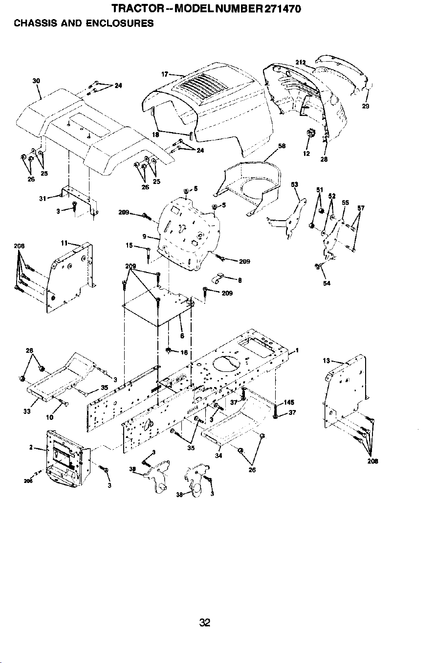
TRACTOR -- MODEL NUMBER 271470
CHASSIS AND ENCLOSURES
12
28
29
57
26
33
10
35
2_
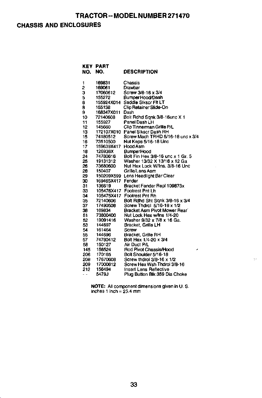
TRACTOR -- MODEL NUMBER 271470
CHASSIS AND ENCLOSURES
KEY PART
NO. NO. DESCRIPTION
1
2
3
5
6
8
9
10
11
12
13
15
16
17
18
24
25
26
28
29
3O
31
33
34
35
37
38
51
52
53
54
55
57
58
145
2O6
208
209
212
169831 Chassis
169O61 DraWoar
17060612 Screw 3/8-16 x 3/4
155272 Bumper Hood/Dash
155924X014 Saddle Slkscr FIt LT
155138 Clip Retainer Slide-On
168347X011 Dash
72140608 Bolt Rdhd Sqnk 3/8-16unc X 1
155927 Panel Dash LH
145660 Clip Tinnerman Grille P/L
172107X010 Panel Slkscr Dash RH
74180512 Screw Mach TRHD 5/16+18 uric x 3/4
73510500 Nut Keps 5/16-18 Unc
15O639X417 HoodAsm
126938X BumperHood
74780616 Bolt Fin Hex 3/8-16 unc x 1 Gr. 5
19131312 Washer 13/32 X 13/16 x 12 Ga
73680600 Nut Hex Lock W/Ins. 3/8-16 Unc
150407 Grille/Lens Asm
150209X599 Lens Headlight Bar Clear
169465X417 Fender
136619 Bracket Feoder Rep1109873x
105476X417 Footrest Pnt Lh
105475)(417 Footrest Pnt Rh
72140606 Bolt Rdhd Sht Sqnk 3/8-16 x 3/4
17490508 Screw Thdrol 5/16-18 x 1/2
169834 Bracket Asm PiVOtMower Rear
73800400 Nut Lock Hex w/Ins 1/4-20
19091416 Washer 9/32 x 7/8 x 16 Ga+
144697 Bracket, Grille LH
161464 Screw
144696 Bracket, Grille RH
74780412 Bolt Hex 1/4-20 x 3/4
150127 Air Duct P/L
156524 Rod Pivot Chassis/Hood
170165 BOdShoulder 5/16-16
17670608 Screw thdrol 3/8-16 x 1/2
170O6612 ScrewHexWshThdroi3/8-16
156494 Insert Lens Reflective
5479J Plug Button BIk 359 Dia Choke
NOTE: All component dimensiot_s given in U. S.
inches 1 inch = 25.4 mm
33
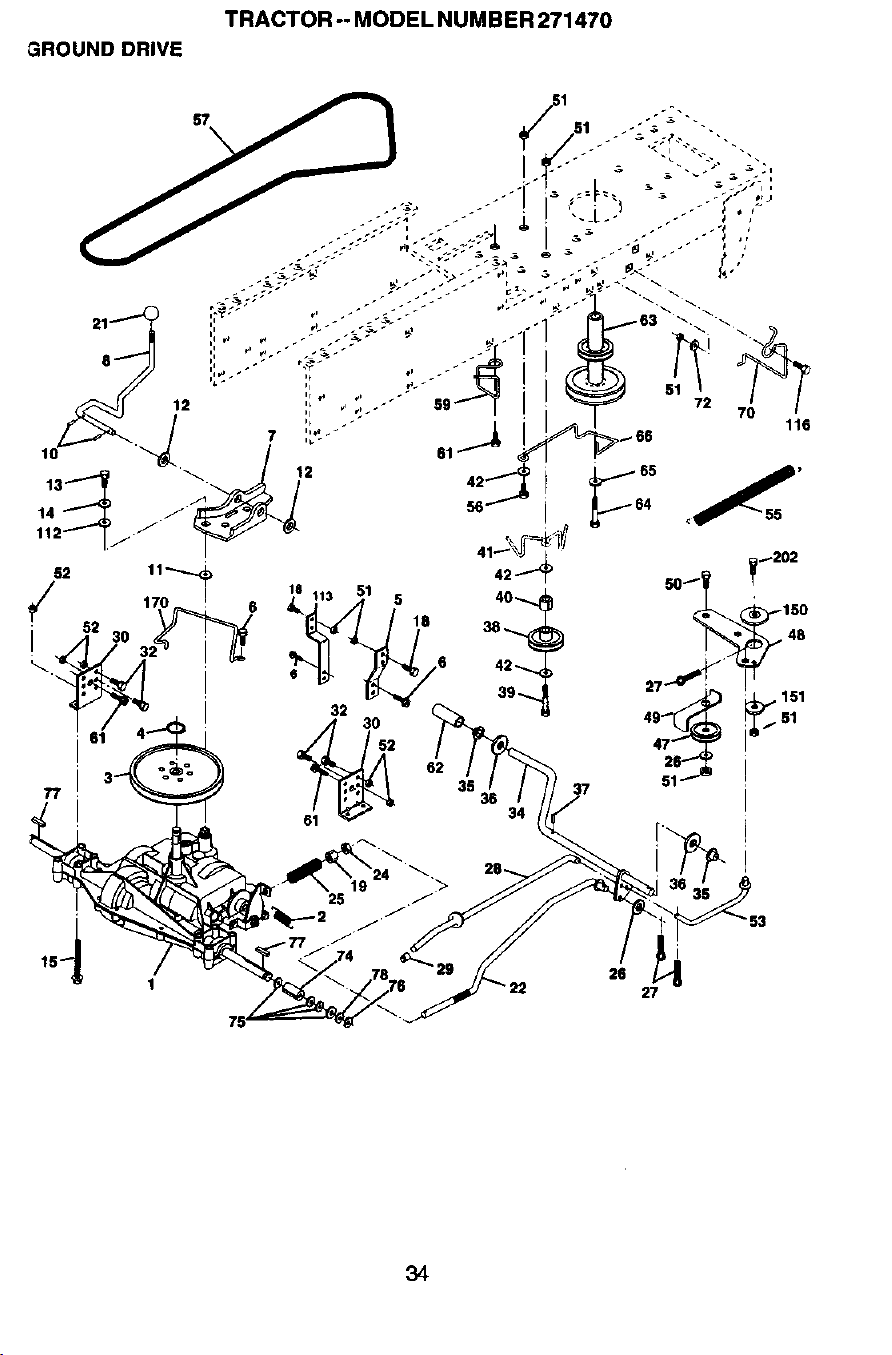
TRACTOR--MODELNUMBER271470
GROUND DRIVE
32
37
26
• 22 27
34
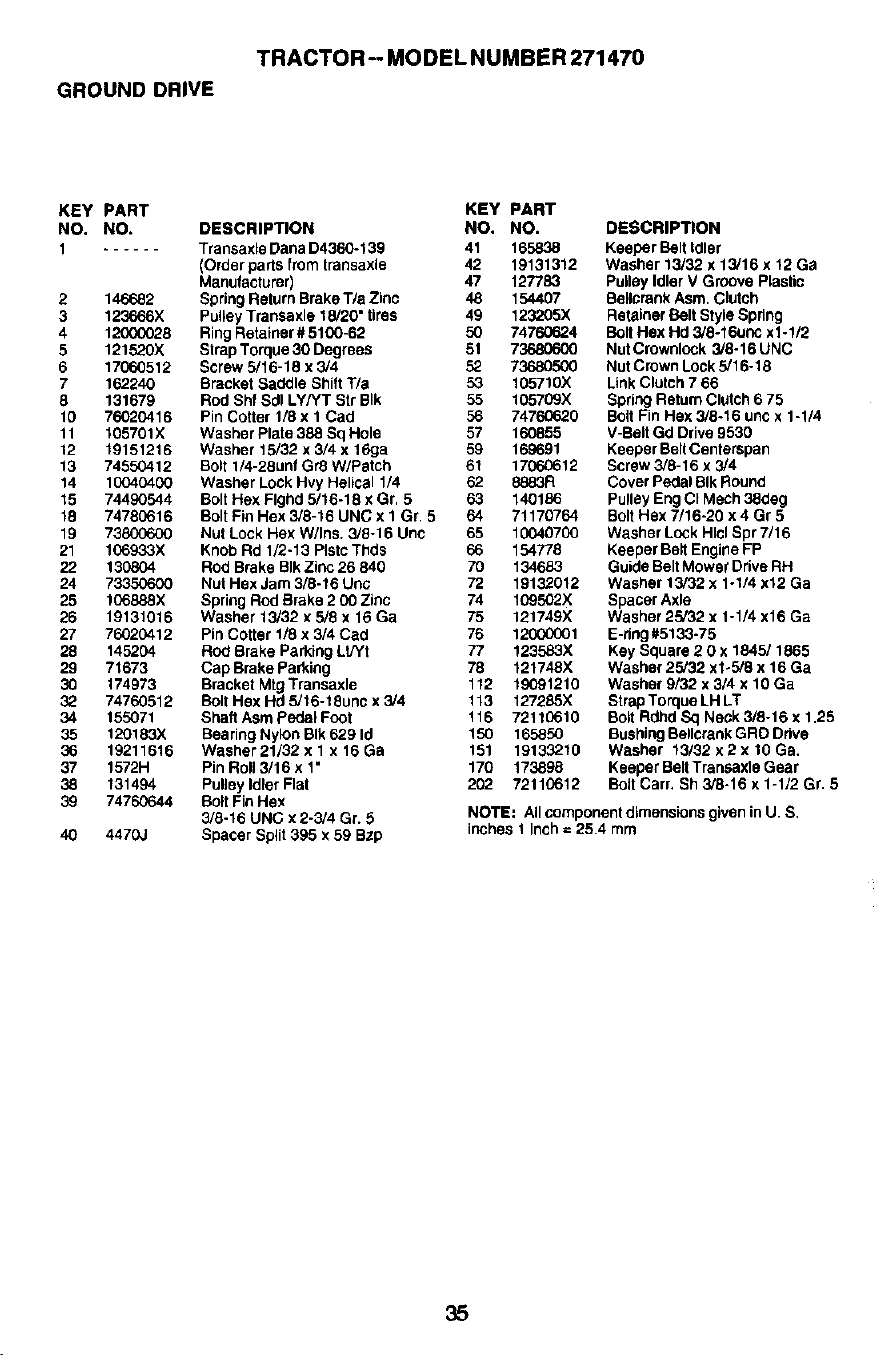
TRACTOR--MODELNUMBER271470
GROUNDDRIVE
KEY PART KEY PART
NO, NO. DESCRIPTION NO. NO.
1 ...... Transaxle Dana D4360-139 41 1658,38
(Order parts from transaxle 42 19131312
Manufacturer) 47 127783
2 146682 Spring Return Brake T/a Zinc 48 154407
3 123666X Pulley Transaxle 15/20" tires 49 123205X
4 120G0028 Ring Retainer # 51(X)-62 50 74760624
5 121520X Strap Torque 30 Degrees 51 73680600
6 17060512 Borew 6/16-18 x 3/4 52 73680500
7 162240 Bracket Saddle Shift T/a 53 105710X
8 131679 Rod Shf Sdl LY/YT Sir BIk 55 105709X
10 76020416 Pin Cotter 1/8 x 1 Cad 56 74760620
11 105701X Washer Plate 388 Sq Hole 57 160855
12 19151216 Washer 15/32 x 3/4 x 16ga 59 169691
13 74650412 Bolt 1/4-28unf Gr8 W/Patch 61 17060612
14 10040400 Washer Lock Hvy HeliCal 1/4 62 8883R
15 74490544 Bolt Hex Flghd 5/16-18 x Gr. 5 63 140186
16 74780616 Bolt Fin Hex 3/8-16 UNC x 1 Gr. 5 64 71170764
19 73800600 NUl Lock Hex W/Ins. 3/9-16 Une 65 10040700
21 106933X Knob Rd 1/2-13 PIstc Thds 66 154778
22 130804 Rod Brake BIk Zinc 26 840 70 134683
24 73350600 Nut Hex Jam 3/8-16 Uric 72 19132012
25 106888X Spring Rod Brake 2 00 Zinc 74 109502X
26 19131016 Washer 13/32 x 5/6 x 16 Ga 75 121749X
27 76020412 Pin Cotter 1/8 x 3/4 Cad 76 12000001
28 145204 Rod Brake Parking Lt/Yt 77 123583X
29 71673 Cap Brake Parking 78 121748X
30 174973 Bracket Mtg Transaxle 112 19091210
32 74760512 Boll Hex Hd 5/16-18unc x 3/4 113 127285X
34 155071 Shaft Asm pedal Foot 116 72110610
35 120183X Bearing Nylon BIk 629 Id 150 165850
36 19211616 Washer 21/32 x 1 x 16 Ga 151 19133210
37 1572H Pin Roll 3/16 x 1" 170 173898
38 131494 Pulloy Idler Flat 202 72110612
39 74760644 Bolt Fin Hex
3/6-16 UNC x 2-3/4 Gr. 5
40 4470,.I Spacer Split 395 x 59 Bzp
DESCRIPTION
Keeper Bolt Idler
Washer 13/32 x 13/16 x 12 Ge
Puiloy Idler V Groove Plastic
Se_lcrank Asm. Clutch
Retainer Belt Stylo Spring
Bolt Hex Hd 3/8-16uric x1-1/2
Nut Crownlock 3/8-16 UNC
Nut Crown Lock 5/16-18
Link Clutch 7 66
Spring Return Clutch 6 75
Bolt Fin Hex 3/8-16 unc x 1-1/4
V-Belt Gd Drive 9530
Keeper Belt Centerspan
Screw 3/8-16 x 3/4
Cover Pedal SIk Round
Pulley Eng CI MeCh 38deg
Bolt Hex 7/16-20 x 4 Gr 5
Washer Lock Hlcl Spr 7/16
Keeper Be_tEngine FP
Guide Belt Mowe_ Drive RH
Washer 13/32 x 1-1/4 x12 Ga
Spacer Axle
Washer 25/32 x 1-1/4 x16 Ga
E-ddg #5133-75
Key Square 2 0 x 1845/1865
Washer 25/32 x1-5/8 x 16 Ga
Washer 9/32 x 3/4 x 10 Ga
Strap Torque LH LT
Bolt Rdhd Sq Neck 3/8-16 x 1.25
Bushing Be,crank GRD Drive
Washer 13/32 x 2 x 10 Ga.
Keeper Belt Transaxlo Gear
Bolt Cart. Sh 3/8-16 x 1-1/2 Gr. 5
NOTE: All component dimensions given in U. S.
inches 1 inch = 25.4 mrn
35
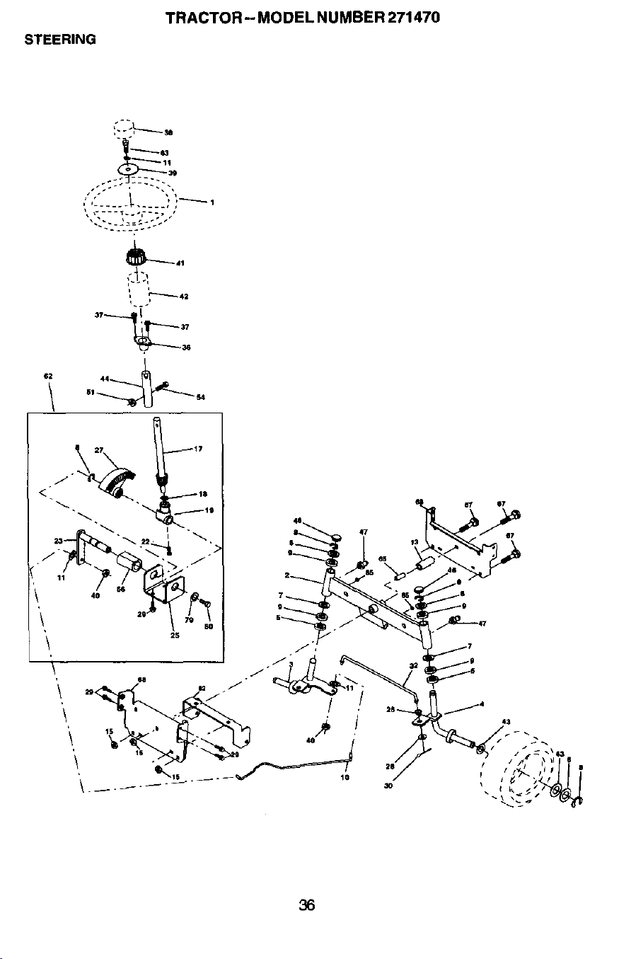
STEERING
TRACTOR- MODEL NUMBER 271470
_~
1f2 4_
51 _4
\
\
/
38
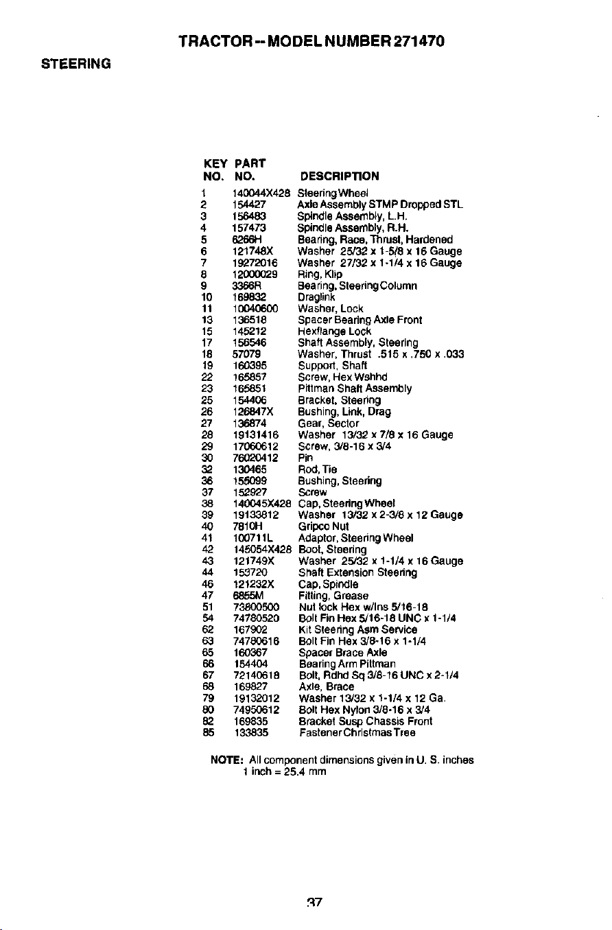
STEERING
TRACTOR -- MODEL NUMBER 271470
KEY PART
NO. NO. DESCRIPTION
1 140044X428 Steering Wheel
2 154427 Axle Assembly STMP Dropped STL
3 156483 Spindle Assemb4y, LH.
4 157473 Spindle Assembly, R.H.
5 626614 Beadng, Race, Thrust, Hardened
6 121748X Washer 25/32 x 1-5/8 x 16 Gauge
7 19272016 Washer 27/32 x 1-1/4 x 16 Gauge
8 12000029 Ring, Klip
9 3366R Bea ring, Steering Column
10 1698-32 Draglink
11 10040600 Washer, Lock
13 136518 Spacer Beadng Axle Front
15 145212 Hexfiange Lock
17 156546 Shaft Assembly, Steering
18 57079 Washer, Thrust .515 x .750 x .033
19 160395 Support, Shaft
22 165857 Screw, Hex Wshhd
23 165851 Piftman Shaft Assembly
25 154406 Bracket, Steedng
26 126847X Bushing, Link, Drag
27 13#874 Gear, Sector
28 19131416 Washer 13/32xT/8x16Gauge
29 17060612 Screw, 3/8-16 x 3/4
30 76020412 Pin
32 130465 Rod, Tie
36 155099 Bushing, Steedng
37 152927 Screw
38 14(XH5X428 Cap, Steedng Wheel
39 19133812 Washer 13/32 x 2-3/8 x 12 Gauge
40 7810H Gripco Nut
41 100711L Adaptor, Steedng Wheel
42 145054X428 Boot, Steedng
43 121749)( Washer 25/32 x 1-1/4 x 16 Gauge
44 153720 Shaft Extension Steering
46 121232X Cap, Spiodle
47 6855M Fitting, Grease
51 73800500 Nut lock Hex w/Ins 5/16-18
54 74780520 Bolt Fin Hex 5/16-18 UNC x 1-1/4
62 167902 Kit Sleedng Asm Service
63 74780616 Bolt Fin Hex 3/8-16 x 1-1/4
65 160_67 Spacer Brace Axle
66 154404 Beadng Arm PiSman
67 72140618 Bolt, Rdhd Sq 3/8-16 UNC x 2-1/4
68 169827 Axle, Brace
79 19132012 Washer 13/32 x 1-1/4 x 12 Ga.
80 7495G612 Bolt Flex Nylon 3/8-16 x 3/4
82. 169835 Bracket Susp Chassis Front
85 133835 Fastener Christmas Tree
NOTE: All component dimensions given in U. S. inches
1 inch = 25.4 mm
_7
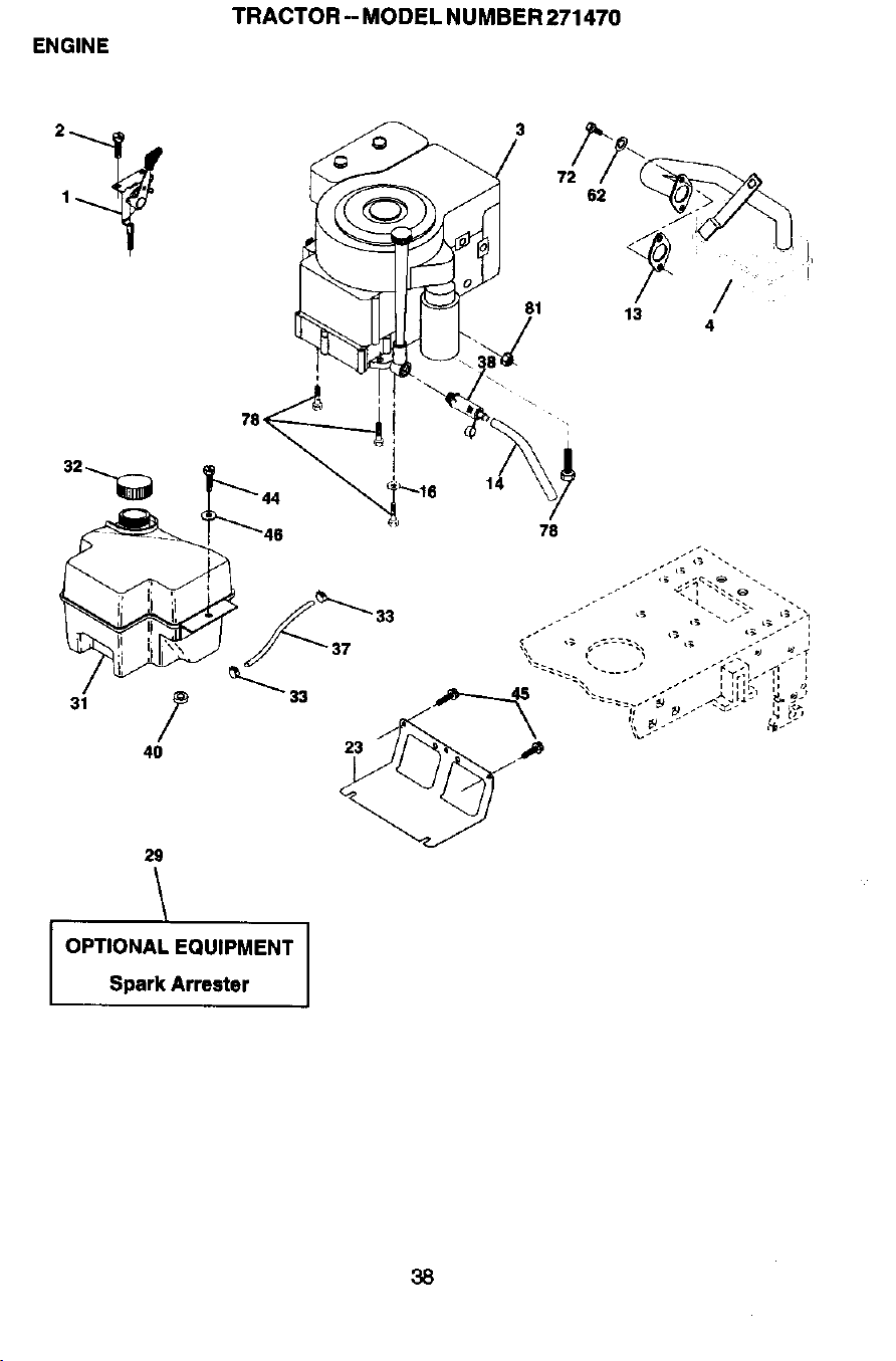
ENGINE
TRACTOR -- MODEL NUMBER 271470
62
81
13
4
78<
\
14
31
29
OPTIONAL EQUIPMENT
Spark Arrester
38
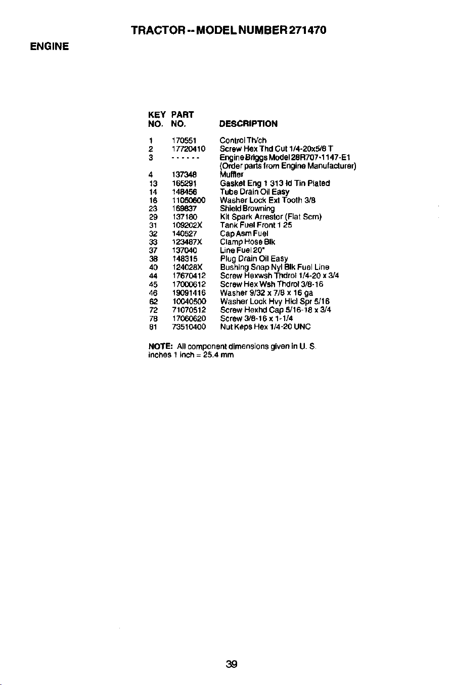
ENGINE
TRACTOR -- MODEL NUMBER 271470
KEY PART
NO. NO. DESCRIPTION
1 170551 ControlTWch
2 17720410 Screw Hex Thd Cut 1/4-20x5/8 T
3 ...... Engine Sriggs Mode128R707-1147-E 1
(Order parts from Engine Manufacturer)
4 137348 Muffler
13 165291 Gasket Eng 1 313 Id Tin Plated
14 148456 Tube Drain Oil Easy
16 11050600 Washer Lock Ext Tooth 3/8
23 169837 Shield Browning
29 137180 Kit Spark Arrestor (Fiat Scm)
31 109202X Tank Fuel Front 1 25
32 140527 CapAsm Fuel
33 123487X Clamp Hose BIk
37 137040 Line Fuel 20"
38 148315 Plug Drain Oil Easy
40 124028X Bushing Snap Nyl BIk Fuel Line
44 17670412 Screw Hexwsh Thdrct 1/4-20 x 3/4
45 17000612 Screw Hex Wsh Thdrct 3/8-16
46 19091416 Washer 3/32 x 7/8 x 16 ga
62 1(_0405(X) Washer Lock Hvy Hicl Spr 5/16
72 71070512 Screw Hexl_ Cap 5/16-18 x 3/4
78 17060620 Screw 3/8-16 x 1-1/4
81 73510400 Nut Kaps Hex 1/4-20 UNC
NOTE: AllcomponentdimensionsgiveninU. S.
inches1inch= 25.4 mm
39
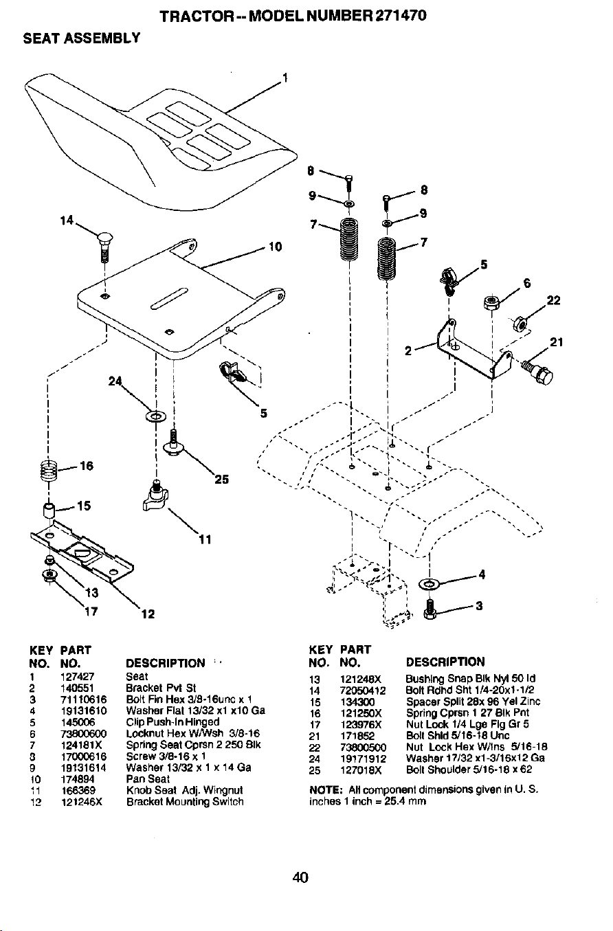
TRACTOR--MODELNUMBER271470
SEATASSEMBLY
KEY PART KEY PART
NO. NO. DESCRIPTION ;' NO. NO. DESCRIPTION
1 127427 Seat 13 121248X Bushing Snap BIk Ny150 Id
2 140551 Bracket Pvt St 14 72050412 Bolt Rdhd Sht 1/4-20x1.1/2
3 71110616 Bolt Fin Hex 3/8-16unc x 1 15 134300 Spacer Split 28x 96 Yel Zinc
4 19131610 Washer Flat 13/32 xl xlO Ga 16 121250X Spring Cprsn 1 27 BIk Pnt
5 145006 Clip Push-lnHinged 17 123976X NUt Lock 1/4 Lge Fig Gr 5
6 73800600 Locknut Hex WPNsh 3/8-16 21 171852 Boll Shld 5/16-18 Unc
7 124181X SpringSeatCpmn2250BIk 22 73800500 Nut LockHexW/tns 5/16-18
3 17000616 Screw 3/6-16 x 1 24 19171912 Washer t7/32 x1-3/16x12 Ga
9 19131614 Washer 13/32 x 1 x 14 Ga 25 127018)( Bolt Shoulder 5/16-18 x 62
10 174894 Pan Seat
11 166369 Knob Seat Adj. Wingnut NOTE: All component dimensions given in U, S.
12 121246X Bracket Mounting Switch inches I inch = 25,4 mm
4O
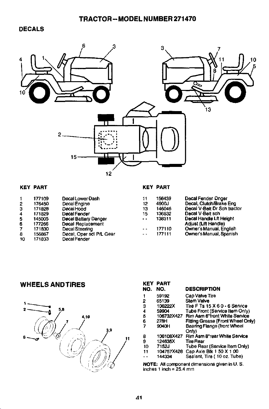
DECALS
TRACTOR-- MODEL NUMBER 271470
4 1o
13
KEY PART
1 177109
2 176450
3 171828
4 171829
5 145G05
6 177266
7 171830
8 156867
10 171833
12
KEY PART
Decal Lower Dash 11 156439
DeCal Engine 12 4900J
DecaIHood 13 146046
Decal Fender 15 136832
Decal Battery Danger - - 138311
Decal Replacement
DecalSteedng - - 177110
Decal Oper sdl P/L Gear - * 177111
Decal Fender
DecalFender Onger
Decal,ClutcWBrakeEng
DeCalV-BeltDr Sch tractor
Decal V-BaRsub
Decal HandleLft Height
Adjust(LiftHandle)
Owner'sManual,English
Owner'sManual,Spanish
WHEELS ANDTIRES
4,10
11
KEY PART
NO. NO. DESCRIPTION
1 59192 Cap Valve Tire
2 65139 Stem Valve
3 166222X Tire F Ts 15 X 6 0 - 6 Service
4 59_4 Tube Front (Service Item Only)
5 106732X427 Rim Asm 6"front White Service
6 278H Filting Grease {Front Wheat Only)
7 9040H Beadng Flange (front Wheel
Only)
8 106108)(427 Rim Asm 8"rear White Service
9 124635X Tira Rear
10 7152J Tube Rear (Service Item Only)
11 104757X428 Cap Axle BIk 1 50 X 1 00
- - 144334 Sealant, Tire ( 10 oz, Tube)
NOTE: All component dimensions given in U. S.
inches 1 inch = 25.4 mm
41
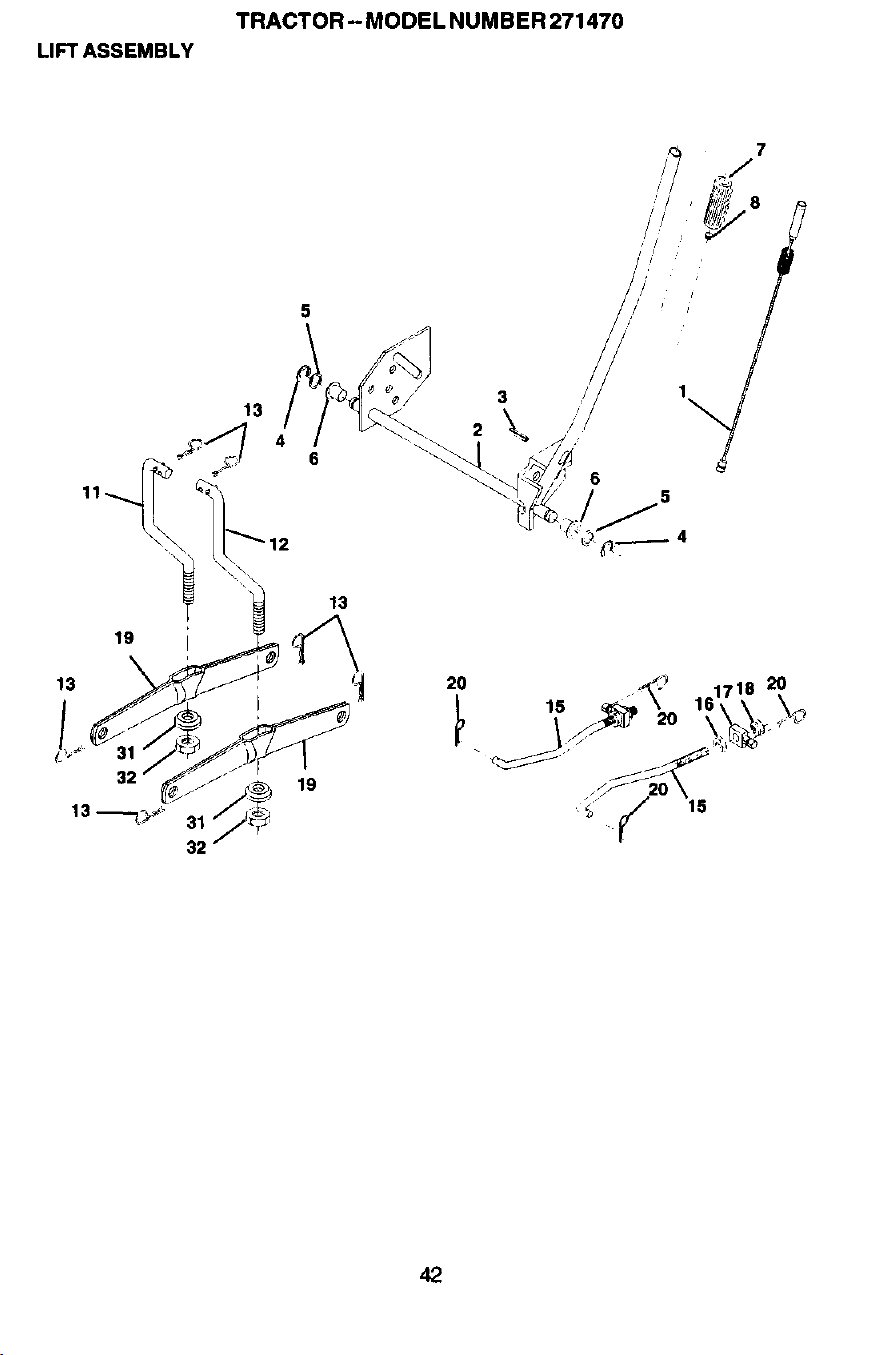
LIFT ASSEMBLY
TRACTOR- MODEL NUMBER 271470
5
19
13
19
3
2
2O
15
6
15
2O
42

LIFT ASSEMBLY
TRACTOR-- MODEL NUMBER 271470
KEY PART
NO. NO. DESCRIPTION
1 159460 Wire Asm Inner W/plunger
2 159471 Shaft Asm Lift
3 105767X Pin Groove 1 500 Zinc
4 12000002 E Ring #5133-62
5 19211621 Washe="Pitd 21/32 X 1 X 21 ga
6 120183X Bearing Nylon BIk 629 Id
7 125631X Grip Handle Fluted BIk
8 122365X Button Plunger Red
11 139865 Link Lift LH
12 139866 Link Lilt RH
13 4939M Retainer Spring
15 173288 Link Front
16 73350800 Nut Jam Hex 1/2-13 Unc
17 130171 Trunnion BIk Zinc
18 73800800 Nut Lock w/Wsh 1/2-18 UNC
19 139868 Arm Suspension Rear
20 163552 Retainer Spring Zinc
31 169865 Bearing Pvt Lift
92 73540600 Nut Crownlock 3/8-24
NOTE: All component dimensions given in U. S.
inches 1 inch = 25,4 mm
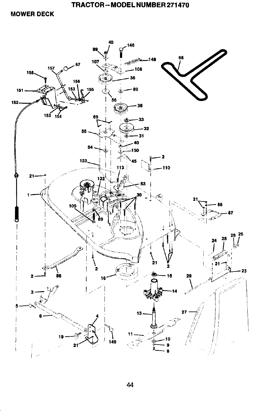
MOWER DECK
TRACTOR -- MODEL NUMBER 271470
4O
!
I
I
[
113 I
I
44
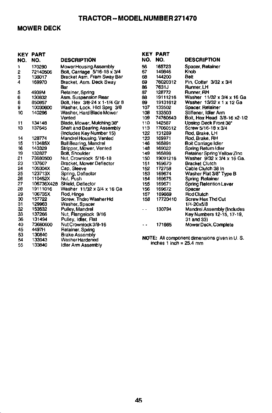
MOWER DECK
TRACTOR - MODEL NUMBER 271470
KEY PART KEY PART
NO. NO. DESCRIPTION NO. NO.
1 170280 Mower Housing Assembly 56 165723
2 72140506 Bolt, Carriage 5/16-18 x 3/4 67 149846
3 138017 Bracket Asrn. Fram Sway Bar 68 144200
4 169970 Bracket, Asm, Deck Sway 69 76020312
Bar 86 7631J
5 49GgM Relainer, Bpdng 87 128772
6 130832 Asm, Suspa_sion Rear 88 19111216
8 850857 Bolt, Hex 3/8-24 x 1-1/4 Gr 8 89 19131612
9 10030600 Washer, Lock, Hicl Sprg 3/8 107 t3350_
10 140296 Washer, Hard Blade Mower 108 133503
Vented 109 74760640
11 134148 Blade, Mower, Mulching 38" 110 142587
13 137645 Shaft and Bearing Assembly 113 17060512
(Includes Key Number 15) 122 131289
14 128774 Mandrel Housing, Vented 123 169971
15 It 0485X BallBearing, Maodrel 146 165891
16 140329 Stripper, Mower, Vented 148 169022
19 132827 Bolt, Shoulder 149 165898
21 73680500 Nut, Crownlock 5/18-18 150 19091216
23 137607 Bracket, Mower Deflector 151 169670
24 105304X Cap, Sleeve 152 172758
25 123713X Spring, Deflector 153 169674
26 110452X Nut, Push 154 169675
27 106736X428 Shield, Deflector 155 169671
28 19111016 Washer 11/32x3/4x16Ga 156 169672
29 106735X Rod,Hinge 157 169669
30 157722 Screw, Thdro Washer Hd 158 17720410
31 129963 Washer, Spacer
32 15,3532 Pulley, Maodrel - - 130794
33 137266 Nut, Flangelock 9/16
36 131494 Pulley, Idler, Flat
40 73680600 Nut Crownlock 3/8-16 - - 171665
45 4497H Retainer, Spdng
53 130840 Brake Assembly
54 133943 Washer Hardenod
55 133840 Idler Arm Assembly
DESCRIPTION
Spacer, Retainer
Knob
Belt
Pin, Cotter 3/32 x 3/4
Runner, LH
Runner, RH
Washer 11132 x 3/4 x 16 Ga
Washer 13/32x 1 x 12Ga
Spacer, Retainer
Stiffener, Idler Arm
Bolt, Hex Head 3/8-16 x2-1/2
Upstop Deck Front 38"
Screw 5/16-18 x 3/4
Rod, Brake, LH
Rod, Brake, RH
Bolt Carriage Idler
Spdng Return Idler
Retainer Spdng Yellow Zinc
Washer 9/32 x 3/4 x 16 Ga.
Bracket Clutch
Cable Clutch 38 In
Washer Flat 3/8" Type B
Spring Retainer
Spring Retention Lever
Spacer
ROdClutch
Screw Hex Thd Cut
1/4-20x5/8
Mandrel Assembly (Includes
Key Numbers 12-15,17÷19,
31 and 33)
Mower Deck, Complete
NOTE: All component dimensions given in U. S.
inches 1 inch = 25,4 mm
45

LIMITED WARRANTY
The Manufacturer warrants to the original consumer purchaser that this product
as manufactured is free from defects in materials and workmanship. For a period
of one (1) year from date of purchase by the original consumer purchaser, we will
repair or replace, at our option, without charge for parts or labor incurred in
replacing parts, any part which we find to be defective due to materials or
workmanship. This Warranty is subject to the following limitations and exclusions.
1.This warranty does not apply to the engine, other than EHP manufactured
transaxle/transmission components, battery (except as noted below) or
components parts thereof. Please refer to the applicable manufacturer's
warranty on these items.
2. Transportation charges for the movement of any power equipment unit or
attachment are the responsibility of the purchaser. Transpodation charges for
any parts submitted for replacement under this warranty must be paid by the
purchaser unless such return is requested by Electrolux Home Products,
3. Battery Warranty: On products equipped with a Battery, we will replace,
without charge to you, any battery which we find to be defective in manufac-
turs, during the first ninety (90) days of ownership. After ninety (90) days, we
will exchange the Battery, charging you 1/12 of the price of a new Battery for
each full month from the date of the original sale. Battery must be maintained
in accordance with the instructions furnished.
4. The Warranty period for any products used for rental or commercial purposes
is limited to 90 days from the date of original purchase.
5.This Warranty applies only to products which have been properly assembled,
adjusted, operated, and maintained in accordance with the instructions
furnished. This Warranty does not apply to any product which has been
subjected to alteration, misuse, abuse, improper assembly or installation,
delivery damage, or to normal wear of the product.
6. Exclusions: Excluded from this Warranty are belts, blades, blade adapters,
normal wear, normal adjustments, standard hardware and normal mainte-
nance.
7. In the event you have a claim under this Warranty, you must return the product
to an authorized service dealer.
Should you have any unanswered questions concerning this Warranty, please
contact:
Electrolux Home Products
a division ofWCI Outdoor Products, Inc.
Outdoor Products Customer Service Dept.
250 Bobby Jones Expressway
Augusta, GA 30909 USA
In Canada contact:
ElectreluxHome Products
a divisionof WCI OutdoorProducts,Inc
7075 Ordan Drive
Mississauga,Ontario
L5T 1K6
giving the model number, serial number and date of purchase of your product
and the name and address of the authorized dealer from whom it was pur-
chased.
THIS WARRANTY DOES NOT APPLY TO INCIDENTAL OR CONSEQUENTIAL
DAMAGES AND ANY IMPLIED WARRANTIES ARE LIMITED TO THE SAME
TIME PERIODS STATED HEREIN FOR OUR EXPRESSED WARRANTIES.
Some areas do not allow the limitation of consequential damages or limitations
of how long an implied Warranty may last, so the above limitations or exclusions
may not apply to you. This Warranty gives you specific legal rights, and you may
have other rights which vary from locale to locale.
This is a limited Warranty within the meaning of that term as defined in the
Magnuson-Moss Act of 1975.
46

SUGGESTED GUIDE FOR SIGHTING SLOPES FOR SAFE OPERATION
GUIDE TH_
ONLY RICE UP AND DOWN HILL,
NOT ACROSS HILL
,4
I_ erate your Tractor up and down the face of slopes (not I
greater than 15_.), .rpver acroes the face. Make turns gradu- I
ally to prevent tipping or _ of control. Exercise extreme I
caution when changing direction on slopes.
I