Loading ...
Loading ...
Loading ...
Section 4 - ADJUSTMENTS & REPAIR
4.3.6. Replacing Bearing In Driven Disc Assembly
(Commercial Models)
If the driven disc bearing fails, remove the driven disc
assembly and replace bearing as follows:
1. Using a small flat blade screwdriver, free the clip
from the transfer rod. Then remove the transfer rod
from the clip and the speed control rod. Refer to Figure
4.11.
2. Using needle nose pliers, unhook the drive spring
and slide the driven disc assembly off the hex shaft.
Refer to Figure 4.12.
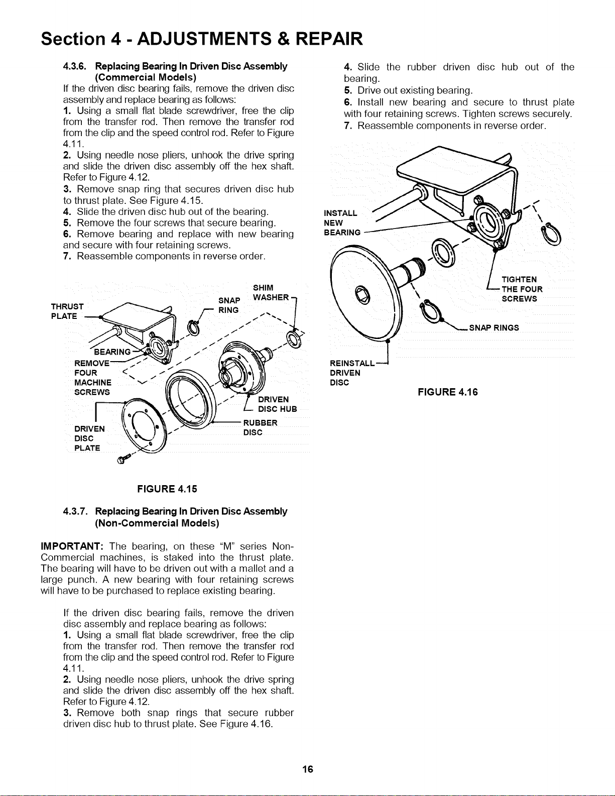
3. Remove snap ring that secures driven disc hub
to thrust plate. See Figure 4.15.
4. Slide the driven disc hub out of the bearing. INSTAL,-
5. Remove the four screws that secure bearing. NEW
6. Remove bearing and replace with new bearing BEARING
and secure with four retaining screws.
7. Reassemble components in reverse order.
4. Slide the rubber driven disc hub out of the
bearing.
5. Drive out existing bearing.
6. Install new bearing and secure to thrust plate
with four retaining screws. Tighten screws securely.
7. Reassemble components in reverse order.
/\
SHIM
SNAP WASHER "-I
THRUST _ /' RING /
P,ATE---.d" _/-- .."'-. /
FOUR &'1 'tl
MACHINE v f/f_'_X_'_ )_.)1
SCREWS _1| _ ."\_\\ _-'_-.,
I
:,,, \\ !, \,/ ._RUBBER
DRIVEN t\-_ )" i--Z DISC
DISC _'_'_ )!
PLATE _,.._._
REINSTALL
DRIVEN
DISC
\
\
FIGURE 4.16
TIGHTEN
FHE FOUR
SCREWS
RINGS
FIGURE 4.15
4.3.7. Replacing Bearing In Driven Disc Assembly
(Non-Commercial Models)
IMPORTANT: The bearing, on these "M" series Non-
Commercial machines, is staked into the thrust plate.
The bearing will have to be driven out with a mallet and a
large punch. A new bearing with four retaining screws
will have to be purchased to replace existing bearing.
If the driven disc bearing fails, remove the driven
disc assembly and replace bearing as follows:
1. Using a small flat blade screwdriver, free the clip
from the transfer rod. Then remove the transfer rod
from the clip and the speed control rod. Refer to Figure
4.11.
2. Using needle nose pliers, unhook the drive spring
and slide the driven disc assembly off the hex shaft.
Refer to Figure 4.12.
3. Remove both snap rings that secure rubber
driven disc hub to thrust plate. See Figure 4.16.
16
Loading ...
Loading ...
Loading ...