Loading ...
Loading ...
Loading ...
13
Installation
Professional Ranges
9
Assemble
& Adjust
Burners
•Replace the burner bowls and burner caps.
•Adjustments should not be required, unless
vibration during transit or variations in local
gas supply make minor adjustments neces-
sary.
CAUTION: Burner adjustments must be made
by a qualified technician at the time of installa-
tion. Extreme care should be used if adjust-
ments are made after installation.
•Burner flames should be blue and stable with
no yellow or yellow tips, excessive noise or
lifting of the flame from the burner. If any of
these conditions exist, check that the air
shutter or burner ports are not blocked. If
one of these conditions continues, adjust the
air shutter as required.
–If the flame is too yellow, there is insufficient
air flow, adjust the shutter counterclockwise
to increase air inlet.
–If the flame is noisy or tends to lift away
from the burner, there is too much air. Turn
the shutter clockwise to reduce air.
The open top burners and grill valves have an
adjustable low setting. Each valve is individu-
ally tested and adjusted before it is shipped.
Minor adjustments may be required due to
fluctuations in local gas pressure. Adjustments
to increase or decrease gas flow may be
necessary.
•Turn knob counter-clockwise to the LITE
position.
•Once lit, turn the know back to the “LOW”
position.
•Remove the knob.
•Insert a thin-blade flat screwdriver into the
valve shaft. (3/32" blade with recom-
mended.)
•Grip the shaft with pliers and turn the
Adjustable
Low Setting
10
screwdriver counter-clockwise to lower the
flame, or clockwise to increase the flame.
CAUTION: Do not turn the flame so low that
it goes out, causing the igniter to spark.
•When the desired setting is made, replace
the knob and turn burner off.
Step
Step
Place the burner grates into operating position.
Press corner of the grate to the cooktop. The
grates should be seated and should not rock.
Models equipped with grill and griddle:
•The grill and griddle are secured with screws at
the front. They are designed to be stationary
and should not to be removed.
Finalize
Installation
•The griddle has two leveling screws beneath
the rear flue cover which can be used to
adjust to the desired slope. The center screw
is for shipping purposes only and should be
removed.
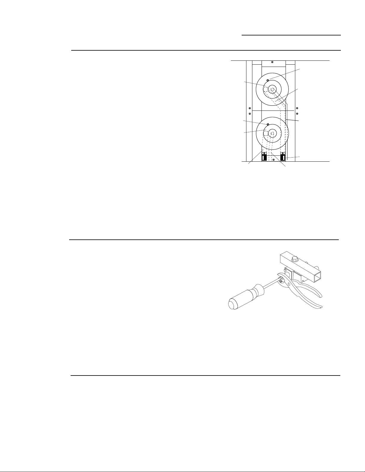
Igniter
Burner
Main Burner
Venturi (rear)
Air Shutter
Burner
Simmer Burner
Venturi (rear)
Simmer Burner
Venturi (front)
Main Burner
Venturi (front)
Igniter
Loading ...
Loading ...
Loading ...