Loading ...
Loading ...
Loading ...
8. Place the range hood near its mounting position and run the
power supply cable through the strain relief into terminal box
(enough to make connection).
9. Tighten the strain relief screws.
The hood attaches to the wall by the 2 mounting screws in the
wood support mounted to the wall in the "Range Hood Mounting
Screws Installation" section.
1. Using 2 or more people, hang the range hood on the the wall
by placing the slotted holes in the range hood back over the 2
screws mounted to the wood support mounted to the wall.
NOTE: If your installation uses the optional duct cover, the
vent system needs to be connected to the hood and the duct
cover mounted to the top of the range hood before tightening
the mounting screws. See steps 5 and 6.
2,
3,
Slide the left mounting plate flange under the bracket.
/- .............................
B
A.Bracket
B.Mounting plate flange
Push the right end of the mounting plate up and snap into
spring tab.
NOTE: The spring tab should be outside of the slot in the
mounting plate.
2. Push the range hood up into the narrow slots, align the
bottom of the hood to the horizontal line, level the hood, and
tighten the 2 mounting screws.
3. Mark 2 lower mounting hole locations. Drill V8" pilot holes if
the holes are located into wood. If holes are not located into
wood, remove the hood and drill two 3/8"pilot holes and insert
10 x 50 mm wall anchors. Remount the hood, level, and
tighten the upper screws. Install 2 - 6 x 80 mm screws into
the lower mounting anchors and tighten.
4. Install 4 - 4.2 x 19 mm screws through the back of the hood
into the wood support and tighten.
5. Connect vent system to hood. Seal all joints with clamps.
6. If your installation uses the optional duct cover, mount it to
the top of the range hood following the instructions supplied
with the duct cover.
1,
csnoe blo Bo Moto
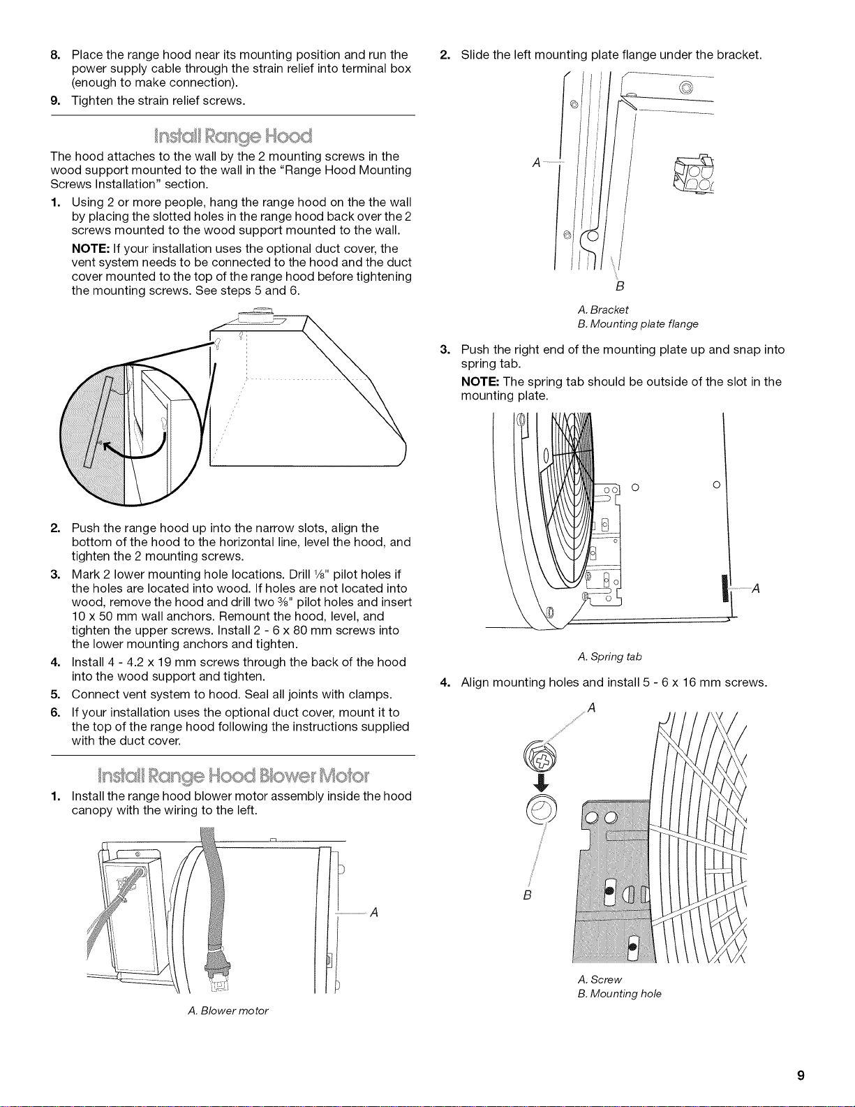
Install the range hood blower motor assembly inside the hood
canopy with the wiring to the left.
A. Blower motor
.................................A
o o
A. Spring tab
4. Align mounting holes and install 5 - 6 x 16 mm screws.
B
A. Screw
B. Mounting hole
Loading ...
Loading ...
Loading ...