Loading ...
Loading ...
Loading ...
WARNING: To prevent serious injury, never perform
maintenance or repairs while the unit is running. Always
allow the unit to cool before servicing or repairing the unit.
Disconnect the spark plug wire to prevent the unit from
starting accidentally.
MAINTENANCE SCHEDULE
Perform these required maintenance procedures at the frequency
stated in the table. These procedures should also be a part of any
seasonal tune-up.
NOTE: Some maintenance procedures may require special tools or
skills. If unsure about these procedures, take the unit to a Sears
or other qualified service dealer. Call 1-888-331-4569 for more
information.
NOTE: Maintenance, replacement, or repair of the emission control
devices and system may be performed by a Sears or other qualified
service dealer. Call 1-888-331-4569 for more information.
NOTE: Please read the California/EPA statement that came with the
unit for a complete listing of terms and coverage for the
emissions control devices, such as the spark arrestor, muffler,
carburetor, etc.
FREQUENCY MAINTENANCE REQUIRED
Every 10 hours Clean and re-oil the air filter. Refer to
Maintaining the Air Filter.
Every 25 hours Check the spark plug condition and gap. Refer
to Maintaining the Spark Plug.
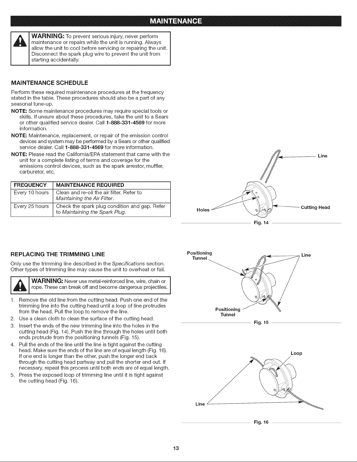
Holes
Fig. 14
Line
Cutting Head
REPLACING THE TRiMMiNG LiNE
Only use the trimming line described in the Specifications section.
Other types of trimming line may cause the unit to overheat or fail.
I _ I WARNING: Never use metal-reinforced line, wire, chain or |
!
rope. These can break off and become dangerous projectiles.
J
1. Remove the old line from the cutting head. Push one end of the
trimming line into the cutting head until a loop of line protrudes
from the head. Pull the loop to remove the line.
2. Use a clean cloth to clean the surface of the cutting head.
3. Insert the ends of the new trimming line into the holes in the
cutting head (Fig. 14). Push the line through the holes until both
ends protrude from the positioning tunnels (Fig. 15).
4. Pull the ends of the line until the line is tight against the cutting
head. Make sure the ends of the line are of equal length (Fig. 16).
If one end is longer than the other, push the longer end back
through the cutting head partway and pull the shorter end out. If
necessary, repeat this process until both ends are of equal length.
5. Press the exposed loop of trimming line until it is tight against
the cutting head (Fig. 16).
Positioning
Tunnel
Tunnel
Line
Fig. 15
Loop
Line
Fig. 16
13
Loading ...
Loading ...
Loading ...