Loading ...
Loading ...
Loading ...
5. Raiseattachment lift lever to its highest
position.
6. Removekey from bag and start the
engine (see "TO START ENGINE" in
the Operationsection of this manual).
After engine has started, move throttle
control to idle position.
7. Release parking brake.
8. Slowly depressforward drive pedal and
drive tractor off skid.
9. Apply brake to stop tractor and set
parking brake.
10.Turnignition key to "STOP" position.
Continue with the instructionsthat follow.
ASSEMBLE FRONT WHEEL TO
MOWER
1. Usingshoulder bolt, washer and
Iocknutfrom parts bag, assemble front
wheel to mower as shown. Tighten
securely.
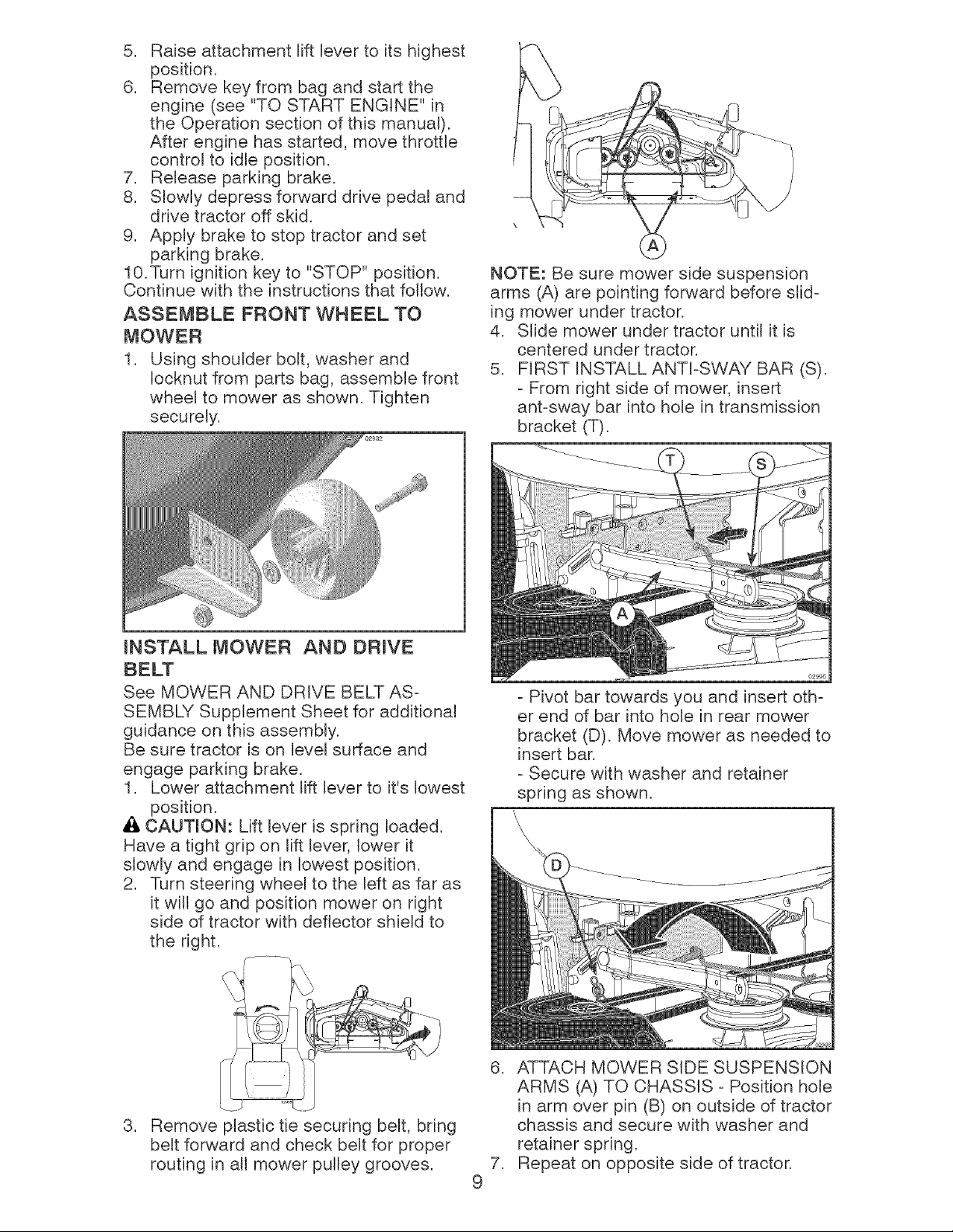
NOTE: Be sure mower side suspension
arms (A) are pointingforward before slid-
ing mower undertractor.
4. Stide mower undertractor until it is
centered undertractor.
5. FIRST INSTALLANTI-SWAYBAR (S).
- From right side of mower,insert
ant-sway bar into hole in transmission
bracket (T).
mNSTALL MOWER AND DRIVE
See MOWER AND DRIVE BELT AS-
SEMBLY Supplement Sheet for additional
guidance on this assembly.
Be sure tractor is on level surface and
engage parking brake.
1. Lower attachment lift lever to it's lowest
position.
Ai, CAUTION: Lift lever is spring loaded.
Have a tight grip on lift lever, lower it
slowly and engage in lowest position.
2. Turn steering wheel to the left as far as
it will go and position mower on right
side of tractor with deflector shield to
the right.
- Pivot bar towards you and insert oth-
er end of bar into hole in rear mower
bracket (D). Move mower as needed to
insert bar.
- Secure with washer and retainer
spring as shown.
,
Remove plastic tie securing belt, bring
belt forward and check belt for proper
routing in all mower pulley grooves.
,
,
9
ATTACH MOWER SIDE SUSPENSION
ARMS (A) TO CHASSIS - Position hole
in arm over pin (B) on outside of tractor
chassis and secure with washer and
retainer spring.
Repeat on opposite side of tractor.
Loading ...
Loading ...
Loading ...