Loading ...
Loading ...
Loading ...
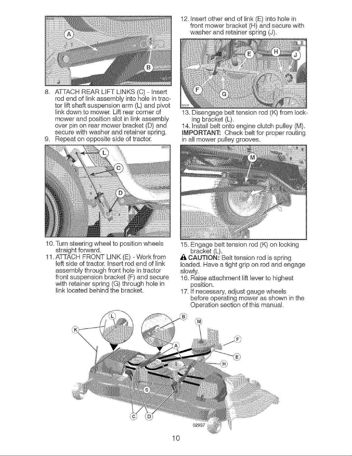
12.Insertotherend of link (E)into holein
front mowerbracket(H)andsecurewith
washerand retainerspring(J).
8. ATTACHREARLIFT LINKS(C)- Insert
rodend of linkassemblyintohole in trac-
tor liftshaft suspensionarm (L)and pivot
linkdownto mower.Liftrear cornerof
mowerand positionslotin linkassemMy
over pin on rearmowerbracket(D)and
securewith washer and retainerspring.
9. Repeaton oppositesideof tractor°
02933
13. Disengage belt tension rod (K) from lock-
ing bracket (L).
14. Install belt onto engine clutch pulley (M).
mMPORTANT: Check belt for proper routing
in all mower pulley grooves.
10. Turn steering wheel to position wheels
straight forward.
11. ATTACH FRONT LINK (E) - VVork from
left side of tractor. Insert rod end of link
assembly through front hole in tractor
front suspension bracket (F) and secure
with retainer spring (G) through hole in
link located behind the bracket.
15. Engage belt tension rod (K) on locking
bracket (L).
CAUTION: Belt tension rod is spring
loaded. Have a tight grip on rod and engage
slowly.
16. Raise attachment lift lever to highest
position.
17. If necessary, adjust gauge wheels
before operating mower as shown in the
Operation section of this manual.
02937
10
Loading ...
Loading ...
Loading ...