Loading ...
2A-IFTHIS IS YOUR REGULATOR:
•Use an adjustable wrench to remove the hex-nut
from the pressure regulator.
(LP/Proio_ne)
LP
Converter
Nut& Pin
GasRow __
IntoRangeStandingpilot NAT
vee°n°tanove
gas shutoff
valveonthe
regulator. "
• Apply sideward finger pressure to remove the
plastic pin from the nut.
Note:Toremove the pin, place the nut on a fiat
surface and pressthe pin sideways with your fingers.
• Rotate the pin 180degrees and snapthe pin back
into the nut.
NAT '_-m_'(LPIPro_ne)
v,
I
l I
• Reinsert the assembly into the regulator and tighten
the hex-nut. Do not overtighten.
2B-IF THIS IS YOUR REGULATOR"
• Use a large, fiat-blade screwdriver or a coin to
remove the cap from the press ure regulator.
Natural
o0÷ 0÷'3
:GasFlow
•Turn the cap over and hook it into the slots. The type
of gas to be used should now be visible on the top of
the cap.....
[STEP 3] CONVERTING THE
SURFACE BURNERS
• Lift the burner assemblies straight up (set aside) to
gain access to the surface burner orifice spuds.
• Using a 5/16" nutdriver, or adjustable wrench,
remove each of the four (4) spuds on the surface
burner gas inlet tubes. Replace them with the
correct gas spuds mounted in a holder at the right
rear of the range, above the regulator. Natural gas
spuds are "BRASS" and
LP gas spuds are
"SILVER". Return
the spuds you
removed from
the inlet tubes
to the holder
above the
regulator. To \_
prevent
leakage,
make sure
the spuds
are securely
screwed
into the gas inlet tubes.
Replacethe burner assemblies.
ISTEP 41ADJ UST OVEN
THERMOSTAT
• Remove all five (5) knobs, including OVEN CONTROL
knob. Remove the four (4) screws located behind the
two (2) inner cooktop knobs.
•Open the oven door. Remove the three (3) screws
located under the manifold panel. Remove the
manifold panel.
• Locate the thermostat bypass screw below the
thermostat shaft. Completely loosen the natural gas
bypass screw (blue) by turning it counterclockwise.
Remove it by gently pulling it out using pliers.
•Replace with the LP bypass screw (white) located in
the envelope near the rear of the range, above the
pressure regulator. Tighten the screw by turning it
clockwise.
Turn Screws Counterclockwise
to Loosen and Use Pliers to Remove
Bypass PilotFlameScrew
Screw
[STEP4 ADJUSTOVEN
THERMOSTAT (continued)
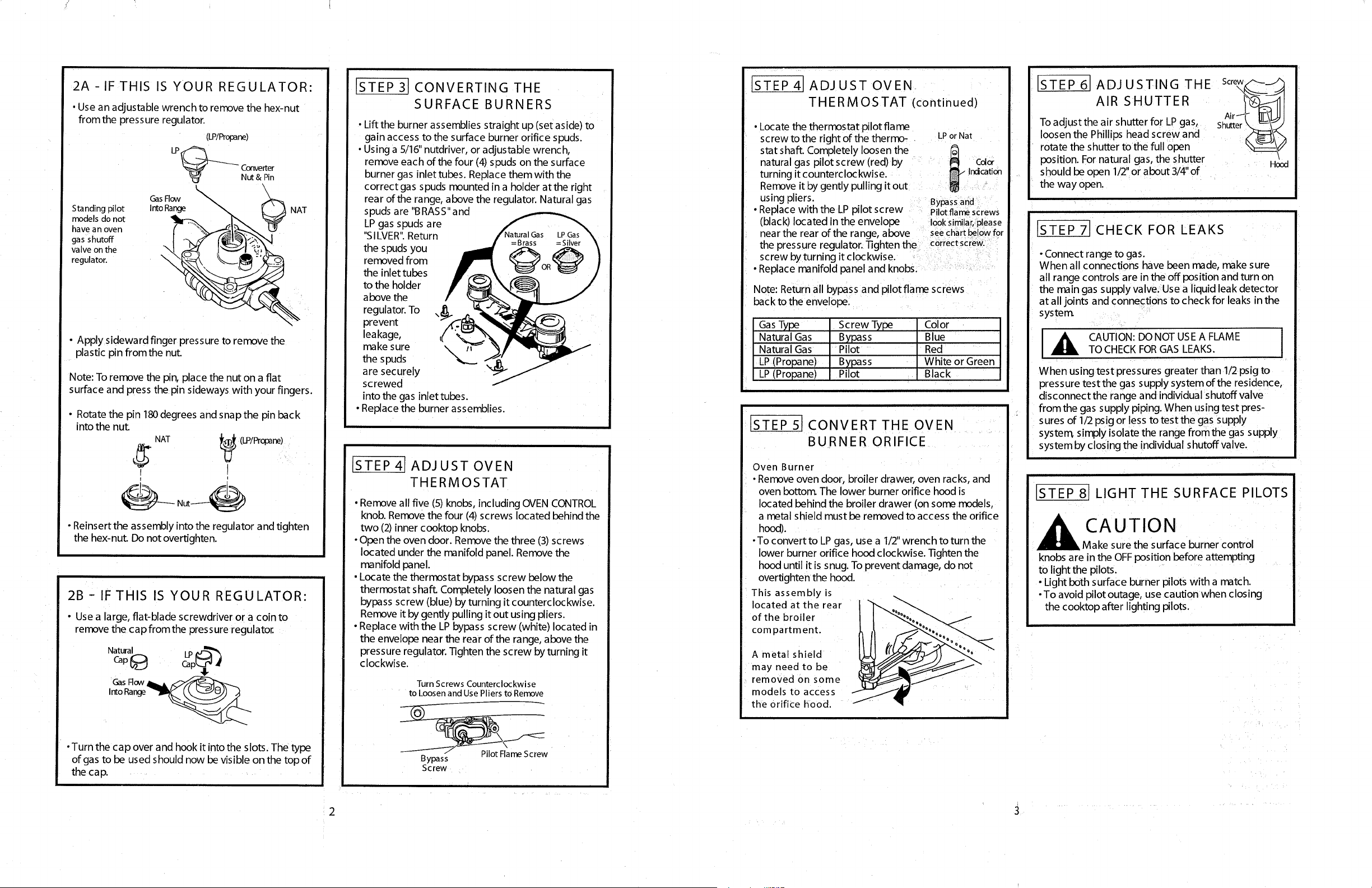
• Locate the thermostat pilot flame
screw to the right of the thermo-
stat shaft. Completely loosen the
natural gas pilot screw (red) by
turning it counterclockwise.
Remove it by gently pulling it out
using pliers.
• Replace with the LP pilot screw
(black) located in the envelope
near the rear of the range, above
the pressure regulator. Tighten the
screw by turning it clockwise.
• Replace manifold panel and knobs.
LPor Nat
Irdcation
Bypassand
Pilotflamescrews
looksimilar,please
seechartbelowfor
correct screw.
Note: Return all bypass and pilot fiame screws
back to the envelope.
Gas Type Screw Type Color
Natural Gas Bypass Blue
Natural Gas Pilot Red
LP (Propane) Bypass White or Green
LP (Propane) Pilot Black
1
STEP 51 CONVERT THE OVEN
BURNER ORIFICE
Oven Burner
• Remove oven door, broiler drawer, oven racks, and
oven bottom The lower burner orifice hood is
located behind the broiler drawer (on some models,
a metal shield must be removed to access the orifice
hood).
•To convert to LP gas, use a 1/2"wrench to turn the
lower burner orifice hood clockwise. Tighten the
hood until it is snug. To prevent damage, do not
overtighten the hood.
This assembly is
located at the rear
of the broiler
compartment.
A metal shield
may need to be
removed on some
models to access
the Orifice hood.
ISTEP61ADJUSTING THE
AIR SHUTTER
Toadjust the air shutter for LPgas,
loosen the Phillips head screw and
rotate the shutter tothe full open
position. Fornatural gas, the shutter
should be open I12"or about 314"of
the way open.
Hood
ISTEP71CHECK FOR LEAKS
• Connect range to gas.
When all connections have been made, make sure
all range controls are in the off position and turn on
the main gas supply valve. Use a liquid leak detector
at all joints and connections to check for leaks in the
syster_
_, AUTION:DONOT USEA FLAME
TOCHECKFORGAS LEAKS.
When using test pressures greater than 1/2psig to
pressure test the gas supply system of the residence,
disconnect the range and individual shutoff valve
from the gas supply piping. When usingtest pres-
sures of 1/2psig or less to test the gas supply
system, simply isolate the range from the gas supply
system by closing the individual shutoff valve.
ISTEP 81 LIGHT THE SURFACE PILOTS
UTION
Make sure the surface burner control
knobs are in the OFF position before attempting
to light the pilots.
• Light both surface burner pilots with a match.
•To avoid pilot outage, use caution when closing
the cooktop after lighting pilots.
2 3
Loading ...