Loading ...
Loading ...
Loading ...
27
CHECKING/CONVERTING THE BURNER ORIFICES
5. If the barbecue does not have the proper
orifices installed for the gas supply you
intend to use, replace them with the correct
orifi ces. Some orifi ces were supplied with the
barbecue. They may also be obtained from the
conversion kit or supplied by your local dealer.
Note: A regulator hose will need to be
connected for conversion to propane
gas.
6. After checking the orifi ce drill size or replacing
the orifi ce, replace the burner over the orifi ce
fitting, sliding it forward, from behind the
forward fi re wall, so the orifi ce is centered
inside the burner gas inlet, and set it gently
onto the burner support. The studs on the
bottom back of the burner must each fit
through their respective holes in the burner
support. This is critical to the safe function of
the barbecue. Finally, re-install the burner clip
(from step 2) around the burner and into the
corresponding holes in the burner support (see
Fig. 27-1).
7. Replace the vaporizer panels and the cooking
grids. If applicable, reinstall the control panel.
MAIN BURNER ORIFICE SIZE CHECKING/
CONVERSION
Before beginning, make sure you have the proper
tools for the task.
This task requires:
• a #2 Phillips-head screwdriver
• a
1
/
2
" deep socket nut driver
Note: It may be necessary to remove the rotisserie
rod before beginning this procedure.
1. Remove cooking grids & vaporizer panels from the
barbecue.
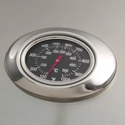
2. Locate the burner. Slightly pinch and remove the
burner clip (located over the rear center of the
burner) from the burner support and set aside.
Then carefully lift the burner from the burner
support and out from the hole in the forward fi re
wall (see Fig. 27-1).
3. Using a
1
/
2
" deep socket nut driver, remove the
orifi ce from the valve. Access this through the
hole in the forward fi rebox plate inside the grill
(see PARTS LIST and Fig. 27-1).
Alternatively, the orifice can be accessed
through the inside of the control panel if the
proper tool is not available. This allows a
1
/
2
"
open-end wrench to be used instead of a
1
/
2
"
deep socket nut driver. To open the control panel,
see the CONTROL PANEL REMOVAL section.
4. Check the number stamped on the face of the
orifi ce (see Table 1). Repeat for each burner as
necessary.
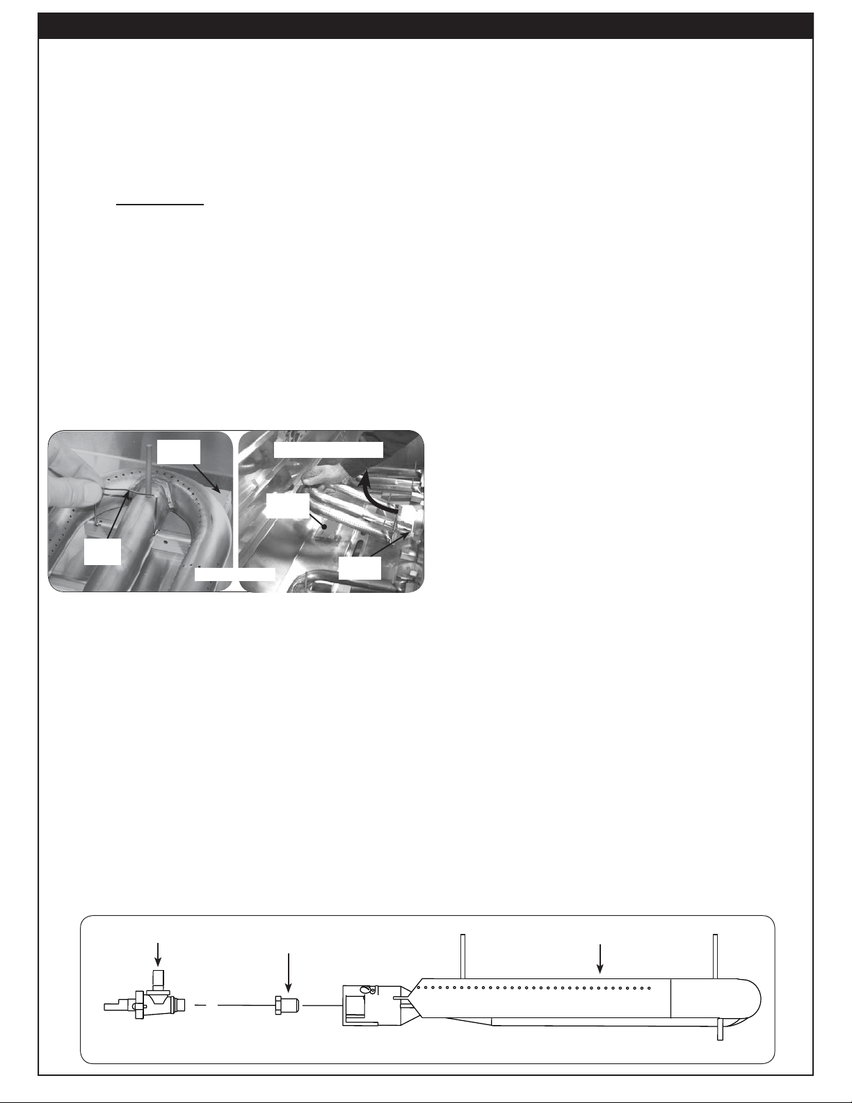
Fig. 27-2 - Burner orifi ce diagram
Orifi ce
Burner
Valve
Removing main burner.
Fig. 27-1
Burner
support
Hole with
orifi ce
Burner
Clip
Burner
support
Loading ...
Loading ...
Loading ...