Loading ...
Loading ...
Loading ...
Installation Instructions.
Installing the Tubing
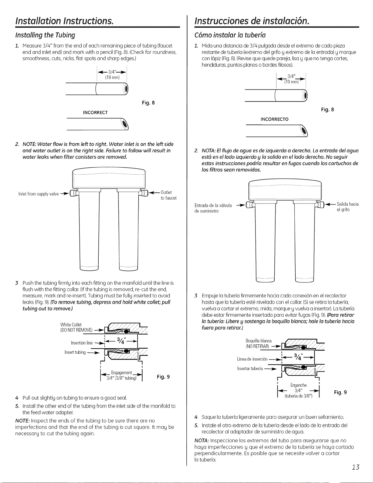
1. Measure 3/4" from the end of each remaining piece of tubing (faucet
end and inletend) and mark with a pencil (Fig.8).(Checkfor roundness,
smoothness,cuts, nicks,flat spots and sharp edges.)
3/4"---_-
19mm
INCORRECT
Fig. 8
2. NOTE:Water flow is from left to right. Water inlet is on the left side
and water outlet is on the right side. Failure to follow will result in
water leaks when filter canisters are removed.
........................................,
Inletfromsupplyvalve_ _ Outlet
tofaucet
Pushthe tubing firmly into each fitting on the manifold until the lineis
flush with the fitting collar. (Ifthe tubing isremoved, re-cut the end,
measure,mark and re-insert).Tubing must befully insertedto avoid
leaks(Fig.9).(Toremove tubing, depress end hold white caller; pull
tubing out to remove.)
WhiteCollet(DONOTREMOVE)
I
Insertionline---_-i_ 3/4
i i
Engagement
4"(3/8"tubing) I
Fig. 9
4 Pullout slightly on tubing to ensure a good seal.
5. Install the other endof the tubing from the inlet sideof the manifold to
the feed water adapter.
NOTE:Inspect the ends of the tubing to be sure there are no
imperfections and that the end of the tubing iscut square. It may be
necessary to cut the tubing again.
instrucciones de instalaci6n.
C6mo instalar la tuberie
Midauna distanciade 3//4pulgadadesdeel extremo de cada pieza
restante detuberia (extremodelgrifo gextremo de la entrada) gmarque
con 16piz(Fig.8).(Revisequequede pareja,lisag que no tenga cortes,
hendiduras,puntos pianoso bordesfilosos).
19mm
INCORRECTO
Fig. 8
2. NOTA:El fluja de agua es de izquierda a derecha. La entrada delagua
est6 en el lado izquierdo g la salida en el lado derecho. No seguir
estas instrucciones podria resultar en fugas cuando los cartuchos de
los filtros sean removidos.
Entradade lav_lvula
desuministro
_]iL .......................................... _ J
Salidahacia
el grifo
Empuje latuberia firmemente hacia coda conexi6n en el recolector
hasta que latuberia est6 niveladocon elcollar. (Siseretira latuberia,
vuelva a cortar el extremo, mida, marque y vuelva a insertar).Latuberia
debeestar firmemente insertada para evitarfugas (Fig.9).(Pare retirar
la tuberia: Libere g sostenga la boquilla blanca; hale la tuberia hacia
fuero paro retirurJ
Boquillablanca ,_,l__J..,._
(NORETIRAR)---_-__/
Lineadeinsercbn_'_ 3/4"'_"
I
' Enganche i
3/4" ---_
tuberiade3/8') I
Fig. 9
4 Saque la tuberia ligeramente para asegurar un buen sellamiento.
S. Instaleel otro extremo de latuberia desde el ladode laentrada del
recolector al adaptador de suministro de agua.
NOTA:Inspeccione los extremos del tubo para asegurarse que no
haya imperfecciones y que el extremo de la tuberia se haya cortado
perpendicularmente. Esposible que se necesite volver a cortar
la tuberia.
J3
Loading ...
Loading ...
Loading ...