Loading ...
Loading ...
Loading ...
Installation Instructions.
Mounting System Installation
Picka locationunder the sink to mount the system. Location should be
easilgaccessible,with clearance between the bottom ofthe filter canisters
and the floor or bottom of the cabinet; ang lesswill resultin difficultUof
removing filter canisters (seeFig.S).Allow enough spaceon either sideof
the sgstem for the tubing connections.
SCREW INSTALLATION
1,
2.
Removethis template from the manual for easier installation.
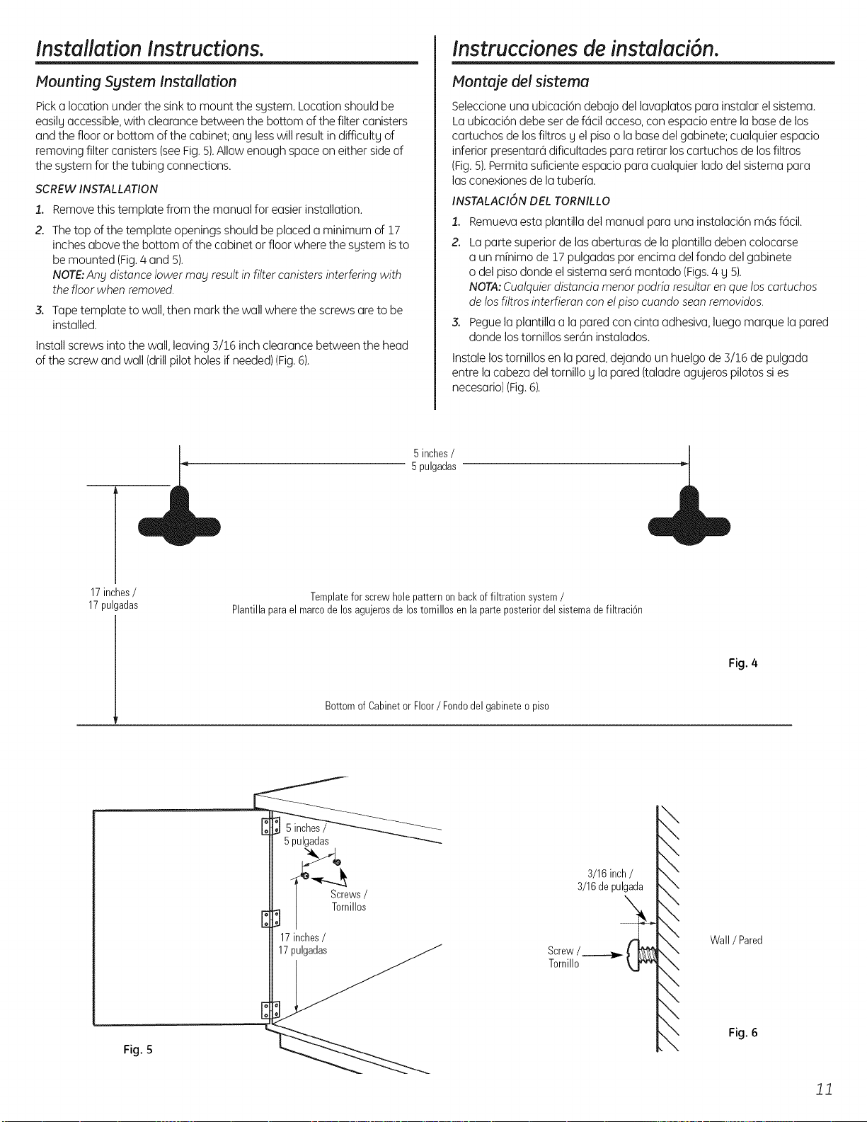
The top of the template openings should be placed a minimum of 17
inches above the bottom of the cabinet or floor where the sgstem isto
be mounted (Fig./4and 5).
NOTE:Any distance lower may resultin filter canisters interfering with
the floor when removed.
3. Tapetemplate to wall,then mark the wall where the screws areto be
installed.
Install screws into the wall, leaving 3/16 inch clearance between the head
of the screw and wall (drill pilot holes if needed)(Fig.6).
instrucciones de insteled6n.
Montoje del sistema
Seleccioneuna ubicaci6n debajo del lavaplatos para instalar el sistema.
La ubicaci6n debe ser de fcicilacceso,con espacio entre la basede los
cartuchos de los filtros g el piso o la base del gabinete; cualquier espacio
inferior presentarh dificultades para retirar loscartuchos de losfiltros
(Fig.5).Permitasuficiente espacio para cualquier lado del sistema para
las conexionesde la tuberia.
INSTALACIONDELTORNILLO
1. Remuevaestaplantilladelmanualparaunainstalaci6nm6sf6cil.
2. Lapartesuperiordelasaberturasde laplantilladebencolocarse
a unminimade 17pulgadasparencimadelfondodelgabinete
odelpisodondeelsistemasere1montado(Figs.4 y 5).
NOTA:Cualquierdistanciamenorpodriaresultarenqueloscartuchos
delosfiltrosinterfieranconelpisocuandoseanremovidos
3. Peguela plantillaa laparedconcintaadhesiva,luegomarquela pared
dondelostornillosser6ninstalados.
Instale lostornillos en la pared,dejando un huelgo de 3/16 de pulgada
entre la cabeza deltornillo y la pared (taladre agujeros pilotos sies
necesario)(Fig.6).
5inches/
5 pulgadas
17inches/
17pulgadas
Templatefor screw holepatternonbackof filtration system/
Plantillaparael marcodelosagujerosde lostornillos enla parteposteriordel sistemadefiltraci6n
Fig. 4
Bottomof Cabinetor Floor/ Fondodelgabineteo piso
17inches/
17pulgadas
Fig. 5
3/16 inch/
3/16depulgada
Screw/
Tornillo
!
Wall / Pared
Fig. 6
JJ
Loading ...
Loading ...
Loading ...