
USER/INSTALLATION GUIDE
US CA
BEVERAGE CHILLER ACCESSORY
BC1-25AC models


3
INTRODUCTION
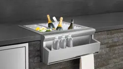
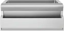
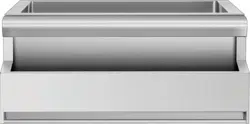
An ultimate entertainer`s feature, the 25” DCS Beverage Chiller is a deep, fully insulated
compartment that can hold up to 17 gallons of ice to chill your refreshments. The Accessory,
designed to house 1-liter bottles, can be installed at the front of your Beverage Chiller,
freeing it up to be used as an outdoor sink.
4
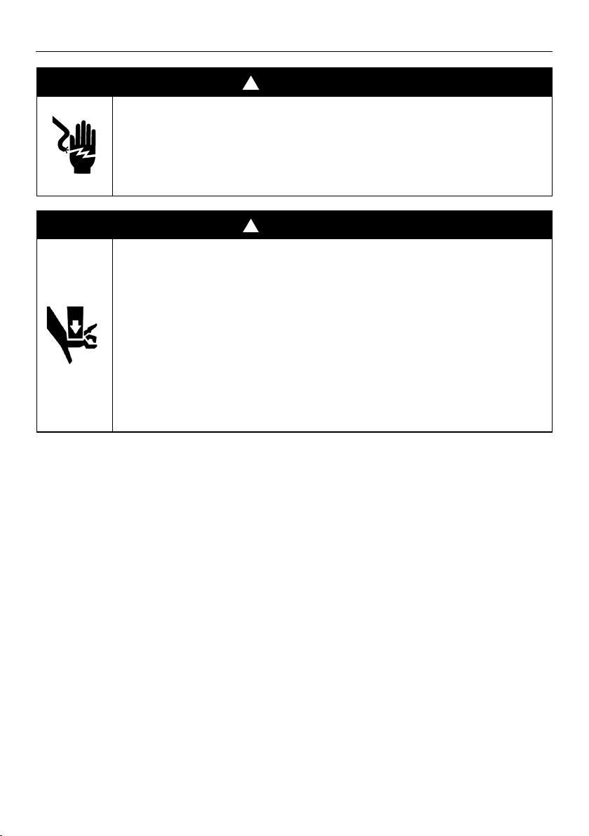
SAFETY AND WARNINGS
!
WARNING!
Cut Hazard
Failure to use caution could result in injury or
cuts.
• Take care - panel edges may be sharp.
!
WARNING!
• Closing drawers may cause injury to
your hands or fingers.
• Always close or open drawers using
their handles.
• Be sure to keep hands away from
drawer edges when opening or
closing drawers.
WARNING
Crush Hazard
Failure to use caution could result in injury or
cuts.
• Closing drawers may cause injury to your hands
or fingers.
• Always close or open drawers using handles.
• Be sure to keep hands away from drawer edges
when opening or closing drawers.
WARNING!
To reduce the risk of injury to persons or damage when using the appliance, follow
the important safety instructions listed below. Read all the guidance before using the
appliance.
z
Do not repair or replace any part of the appliance unless specifically recommended in
the user guide. All other servicing should be undertaken be a Fisher & Paykel trained
and supported service technician or qualified person.
z
Do not remove permanently affixed labels, warnings, or plates from the product. This
may void the warranty.
z
Please leave these instructions with the appliance.
z
Do Not store or use gasoline or other flammable vapors and liquids inside or in the
vicinity of this or any other appliance.
z
Never store a spare LP cylinder inside or near this unit.
5
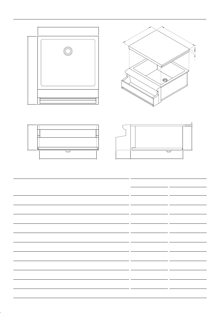
PRODUCT DIMENSIONS
PRODUCT DIMENSIONS
BC1-25AC MODELS
INCHES MM
A Overall height
10 3/8 263
B Overall width
25 1/16 637
C Overall depth (beverage chiller + bottle holder)
28 711
D Depth of beverage chiller chassis
21 1/16 535
E Width of beverage chiller chassis
24 1/8 613
F Height below countertop
9 13/16 249
G Height of surface above countertop
9/16 14
H Depth from bottle holder to front of chiller
6 1/16 154
I Depth of lid
22 1/8 562
J Width of lid
26 5/16 669
K Height of lid
1 11/16 43
B
C
k
j
i
A
E h D
f
G
PLAN
FRONT PROFILE
6
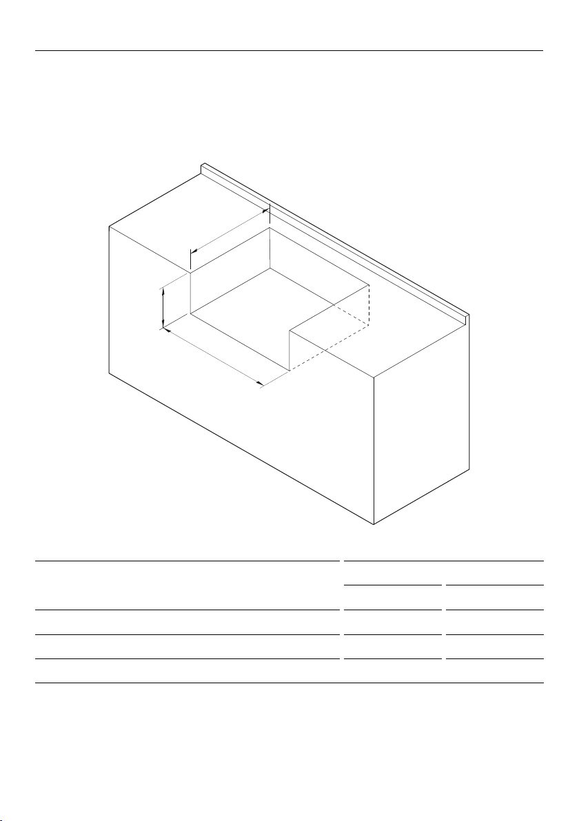
CUTOUT DIMENSIONS
CUTOUT DIMENSIONS
BC1-25AC MODELS
INCHES MM
A Height of cutout
9 13/16 250
B Depth of cutout
21 5/8 550
C Width of cutout
24 3/16 615
Ensure the base of the cavity is level, square and able to support the weight of the product
when full. Any cabinet and/or ground preparation must be completed prior to installation
and all support structures must be constructed of materials resistant to moisture damage.
With bottle holder
a
b
c
7
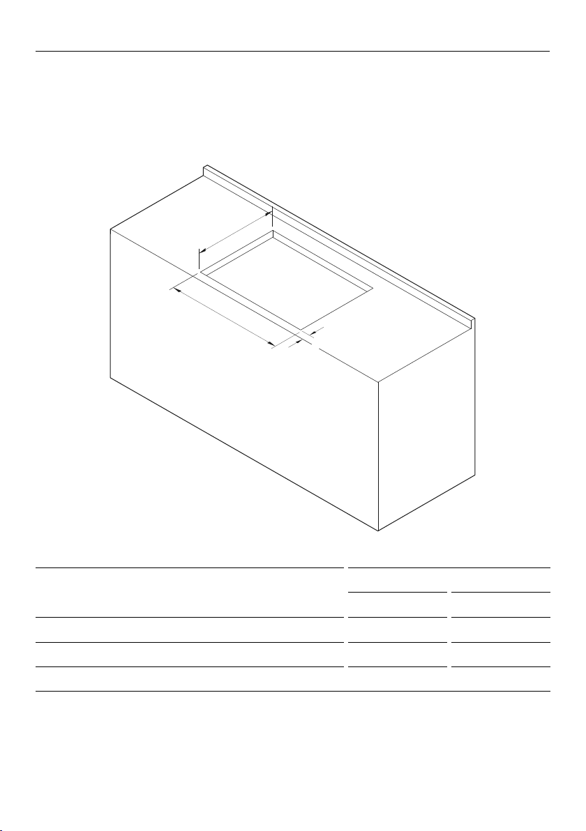
CUTOUT DIMENSIONS
CUTOUT DIMENSIONS
BC1-25AC MODELS
INCHES MM
A Depth of cutout
21 1/16 535
B Width of cutout
24 3/16 615
C Min. distance from front of countertop to cutout
9/16 15
Without bottle holder
Ensure the base of the cavity is level, square and able to support the weight of the product
when full. Any cabinet and/or ground preparation must be completed prior to installation
and all support structures must be constructed of materials resistant to moisture damage.
a
C
b
8
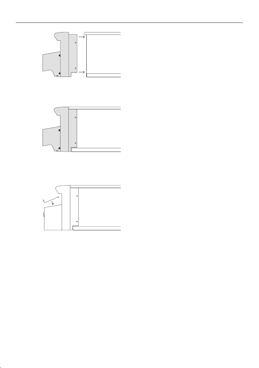
ATTACH THE BOTTLE HOLDER TO UNIT
Align the bottle holder onto the
front of the Beverage Chiller.
Fit the drip tray to the bottom of
the holder.
Attach the bottle holder to the Beverage
Chiller using the screws provided.
1
3
2
9
SECURE PRODUCT INTO CUTOUT
Lower the chiller into the cutout,
ensuring the drain outlet is accessible.
Secure the beverage chiller into place by
tightening the clamping screws against
the counter-top on all sides.
The Beverage Chiller should be connected to a permanent waste drainage system.
Connection: 1-1/2” NPS male thread.
Connection must be carried out by a certified plumber in accordance with local codes and
regulations.
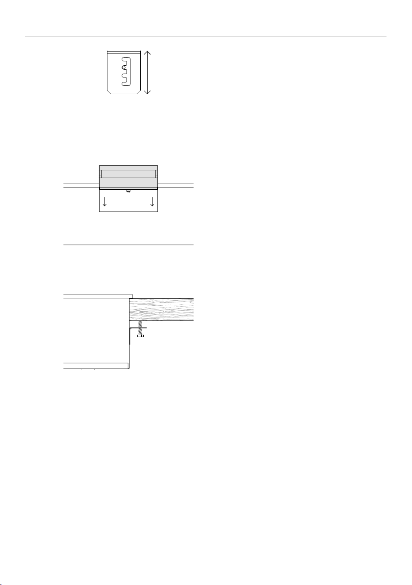
Locate the mounting holes on each
side of the beverage chiller and screw
in the provided mounting clamps at the
appropriate level for the counter-top.
2
3
1

10
FINAL CHECKLIST
Complete and keep for safe reference:
Mode
Serial No.
Purchase Date
Purchaser
Dealer
Suburb
Town
Country
Are products secure and level within the enclosure?
Are the clamping brackets installed correctly?
All internal packaging and any adhesive residue has been removed?
Have all the suitable plumbing connections been checked?
Have all warning labels been removed and supplied to customer for future reference?
Read all installation instructions in this manual to see if the unit has been correctly
installed. Ensure that installation has been completed correctly before use.


US CA
592077A 11.19
DCSAPPLIANCES.COM
© Fisher & Paykel Appliances 2019. All rights reserved.
The product specifications in this document apply to the specific
products and models described at the date of issue. Under our policy
of continuous product improvement, these specifications may change
at any time. You should therefore check with your Dealer to ensure this
booklet correctly describes the product currently available.