PRO.FORM"
CAFES5
SE /AR8
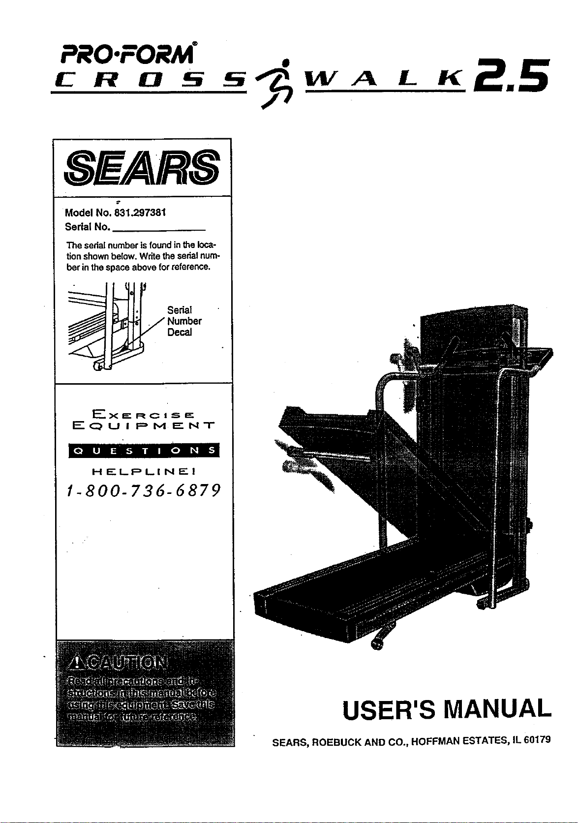
Model No. 831.297381
Serial No.
The sedalnumberisfoundin theloca-
tionshownbelow.Writetheserialnum-
berinthespaceaboveforreference.
Serial
qumber
Decal
E_x J=- R C i S I="
EQUIPMENT
[e] ill| :nh,! n |a| • ii_
H F'LPLI N El
1-800-736-6879
USER'S MANUAL
SEARS, ROEBUCK AND CO., HOFFMAN ESTATES, IL 60179

TABLE OF CONTENTS
IMPORTANT PRECAUTIONS .... * .............................. 2
• .* .. ***.o *.°.**.***.-*******l
BEFORE YOU BEGIN . . 4
.*.**. * ..*.*****.°...°****..**.*°.*.**'* o.*.**** **o***o°
• *l*°*°**** * *
ASSEMBLY ....... .5
,,.,,.,***...°,..°.°,.,,o**,....o.****..**.......**°.....*****..° °. • * • *
OPERATION AND ADJUSTMENT ...... 7
• ,**,,. =....°.......o****°°.o***°......°°..o**_*o...*° •
HOW TO FOLD AND MOVE THE TREADMILL ..................... 10
. °...*°..o°*.****°..°° .***. *.
TROUBLE-SHOOTING ....................................................... : ............. 12
14
CONDITIONING GUIDELINES .... ... .....
ORDERING REPLACEMENT PARTS .................................................. Back Cover
FULL 90 DAY WARRANTY ..... Back Cover°°*** ** °*** .** °* * ** .*. • * .***°** **.* * *,*.* .*
Note: A HARDWARE IDENTIFICATION CHART, an EXPLODED DRAWING and a PART UST are attached to
the center of this manual. Please save them for future reference.
IMPORTANT PRECAUTIONS
2
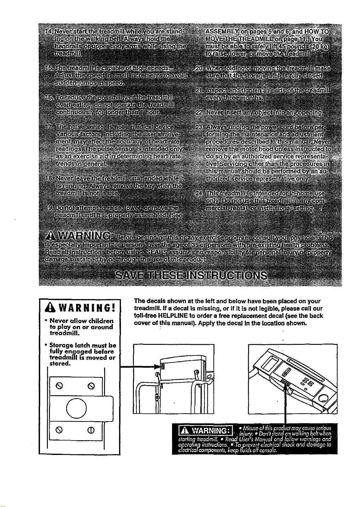
_L,WARNING|
• Never allow children
to play on or around
treadmill.
• Storage latch must be
fully en._laged before
treadmill is moved or
stored.
© l
°
The decals shown at the left and below have been placed on your
treadmill. If a decal is missing, or if it is not legible, please call our
toll-free HELPLINE to order a free replacement decal (see the back
cover of thls manual). Apply the decal in the Iocatloo shown.
BEFORE YOU BEGIN
Thank you for selecting the PROFORM =CROSS-
WALK 2.5 treadmill. The CROSSWALK 2.5 treadmill
blends advanced technology with innovative design to
let you enjoy an excellent form of cerdiovasculat exer-
cise in the convenience and privacyof your home.
For your benefit, read this manual carefully before
using the treadmill. Ifyou have additional questions,
please cell our toll-free HELPUNE at 1;800-7366879,
Monday through Saturday, 7 a.m. until7 p.m. Central
Time (excluding holidays). To help us assist you,
please note the product model number and serial num-
ber before calling. The model number of the treadmill
is 831.297381. The serial number can be found on a
decal attached to the treadmill (see the front cover of
this manual for the location).
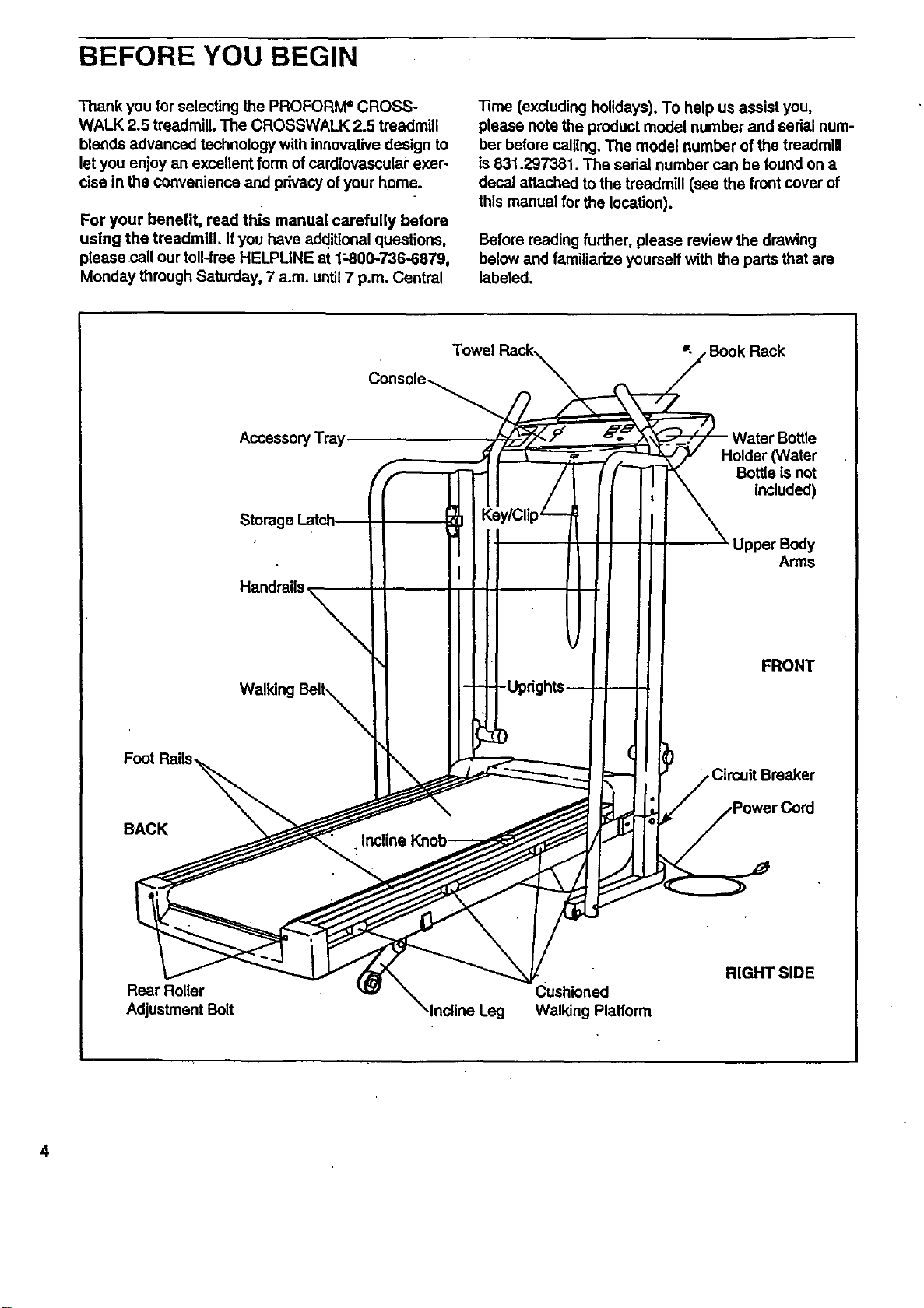
Before reading further, please review the drawing
below and familiarize yourself with the pads that are
labeled.
Foot F
BACK
Accessory Tray
Storag_
Handrails,
Walking Belt_
• Incline I
Holder (Water
Bottle isnot
included)
Up_rBody
Arms
FRONT
•Circuit Breaker
Rear Roller
Adjustment Belt
Cushioned
Walking Platform
RIGHT SIDE
4
ASSEMBLY
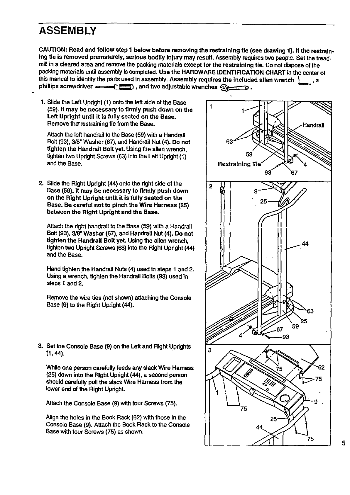
CAUTION: Read and follow step I below before removing the restraining tie (see drawing 1). If the restrain.
Ing tie is removed prematurely, serious bodily Injury may result, Assembly requires two people. Set the tread-
millin a cleared area and remove the packing materials except for the restraining tie. Do not dispose of the
packing materials until assembly iscompleted. Use the HARDWARE IDENTIFICATION CHART in the center of
this manual to identify the parts used in assembly. Assembly requires the Included allen wrench L, a
phillips screwdriver ,,====_, and two adjustable wrenches _:;::::::_D.
1. Slide the Left Upright (1) onto the left side of the Base
(59). It may be necessary to firmly push down on the
Left Upright until it Is fully seated on the Base.
Remove the'restraining tie from the Base.
Attach the left handrail tothe Base (59) with a Handrail
Bolt(93), 3/8" Washer (67), and Handrail Nut (4). Do not
tighten the Handrail Bolt yet. Using the allen wrench,
tightentwo Upright Screws (63) intothe LeftUpdght (1)
and the Base.
2, -Slide the Right Upright (44) ontothe right side of the
Base (59). It may be necessary to firmly push down
on the Right Upright until it is fully seated on the
Base. Be careful not to pinch the Wire Harness (26)
between the Right Upright and the Base.
Attach the dght handrail to the Base (59) with a Handrail
Bolt (93), 3/8" Washer (67), and Handrail Nut (4). Do not
tighten the Handrail Bolt yet. Using the allen wrench,
tighten two Upright Screws (63) into the Right Updght (44)
and the Base.
Hand tighten.the Handrail Nuts (4) used in steps I and 2.
Using a wrench, tighten the Handrail Bolts (93) used in
steps 1 and 2.
Remove the wire ties (not shown) attaching the Console
Base (9) to the Right Upright (44).
3. Set the Console Base (9) on the Left and Right UPdghts
(1, 44).
While one person carefully feeds any slack Wire Hamess
(25) down into the Right Updght (44), a second person
should carefully pull the slack Wire Harness from the
lower end of the Right Upright.
Attach the Console Base (9) with four Screws (75).
Alignthe holes in the Book Rack (62) with those in the
Console Base (9). Attach the Book Rack to the Console
Base with four Screws (75) as shown.
59
93
75
5
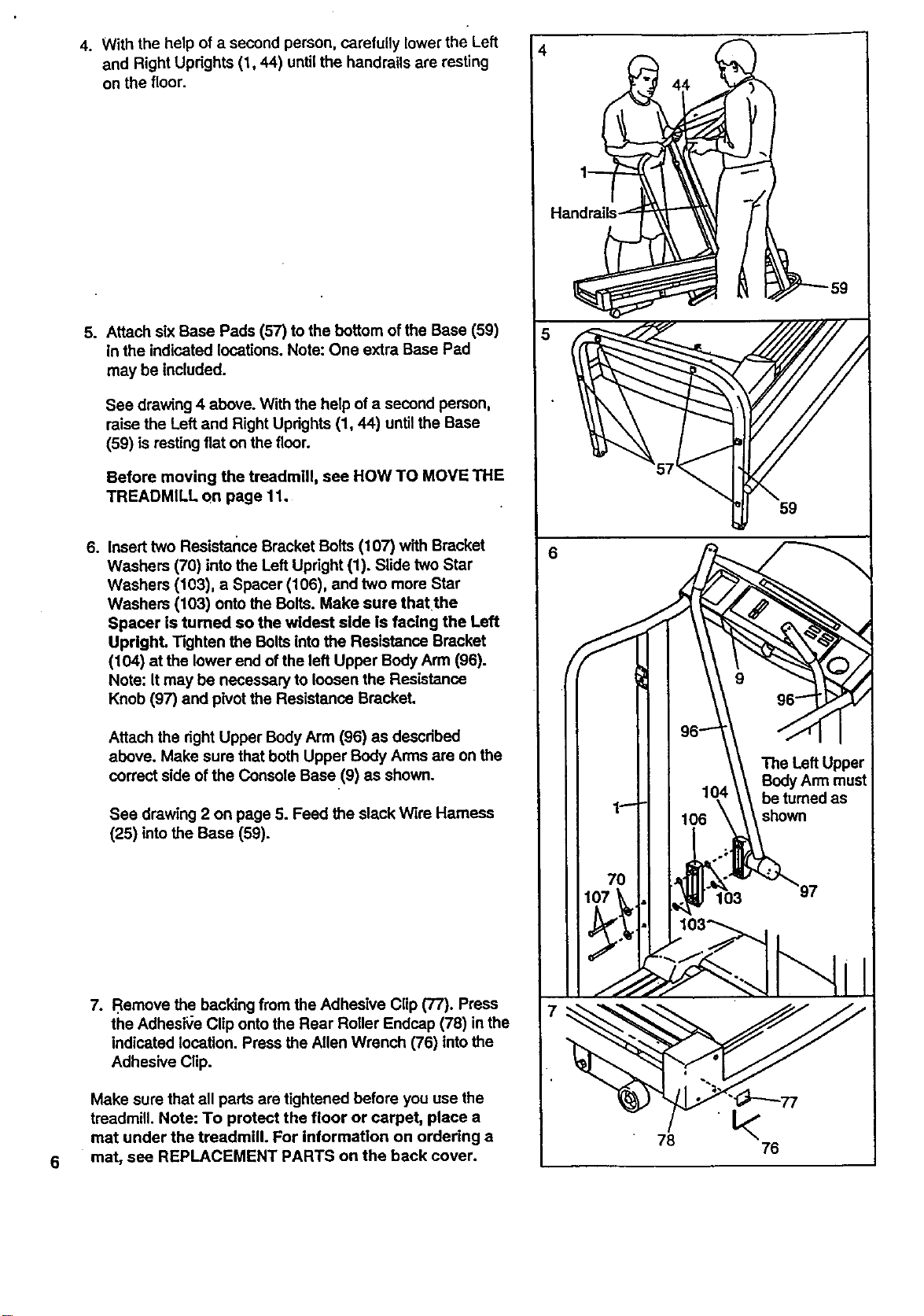
4. Withthehelpofa second person, carefully lower the Left
and Right Updghts (1, 44) until the handrails are resting
on the floor.
.
Attach six Base Pads (57) to the bottom of the Base (59)
in the indicated locations. Note: One extra Base Pad
may be included.
See drawing 4 above. With the help of a second person,
raise the Left and Right Updghts (1, 44) until the Base
(59) is resting flat on the floor.
Before moving the treadmill, see HOW TO MOVE THE
TREADMILL on page 11.
. Insert two Resistartce Bracket Bolts (107) with Bracket
Washers (70) intothe Left Updght (1). Slide two Star
Washers (103), a Spacer (106), and two more Star
Washers (103) onto the Bolts. Make sure that the
Spacer is turned so the widest side is facing the Left
Upright. Tighten the Bolts intothe Resistance Bracket
(104) at the lower end of the left Upper Body Arm (96).
Note: It may be necessary to loosen the Resistance
Knob (97) and pivotthe Resistance Bracket.
Attach the right Upper Body Arm (96) as descdbed
above. Make sure that both Upper Body Arms are on the
correct side of the Console Base (9) as shown.
See drawing 2 on page 5. Feed the slack Wire Harness
(25) into the Base (59).
7. Remove the backing from the Adhesive Clip (77). Press
the AdhesiVe Clip onto the Rear Roller Endcap (78) in the
indicated location. Press the Allen Wrench (76) intothe
Adhesive Clip.
Make sure that all pads are tightened before you use the
treadmill. Note: To protect the floor or carpet, place a
mat under the treadmill. For informatlon on ordering a
mat, see REPLACEMENT PARTS on the back cover.
4
5
7
44
78
t<
76
OPERATION AND ADJUSTMENT
THE PERFORMANT LUBE TM WALKING BELT
Your treadmill features a walking belt coated with
PERFORMANT LUBETM, a high-performance lubricant.
IMPORTANT: Never apply silicone spray or other
substances to the walking belt or the walklng plat-
form. They will deteriorate the walking belt and
cause excessive wear.
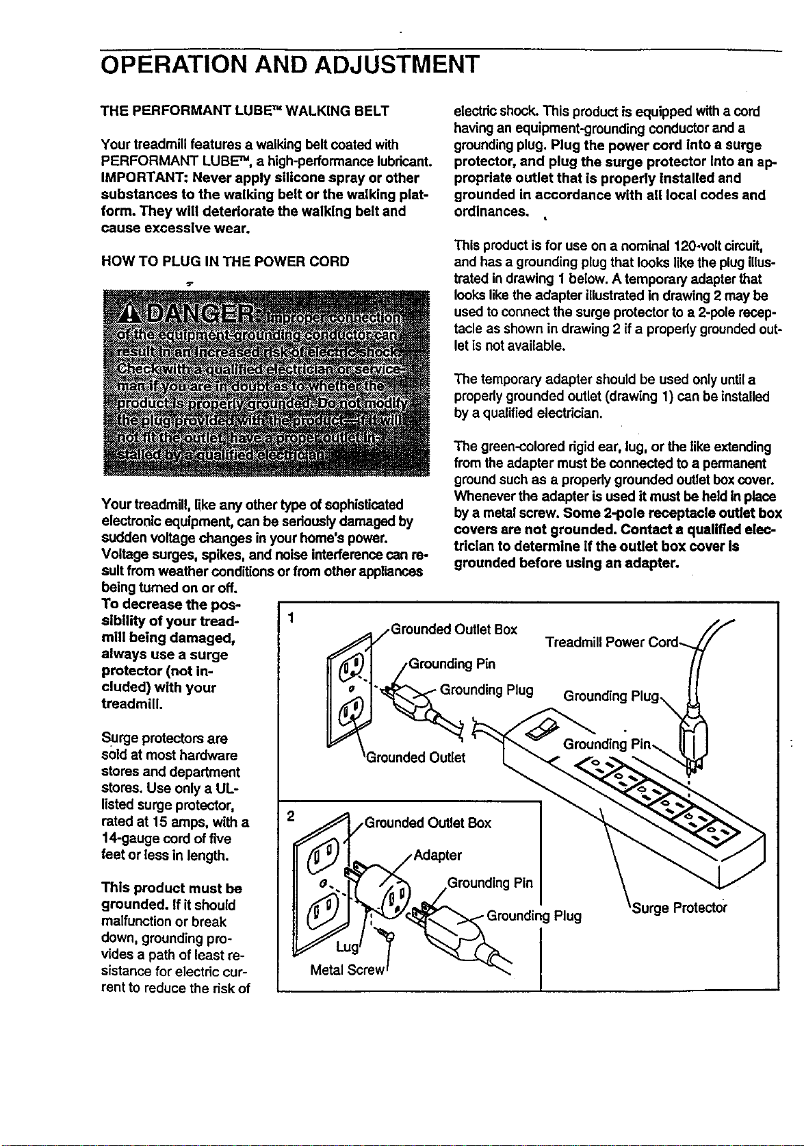
HOW TO PLUG IN THE POWER CORD
electdc shock. This product is equipped with a cord
having an equipment-grounding conductor and a
grounding plug. Plug the power cord Into a surge
protector, and plug the surge protector Into an ap-
propdate outlet that is properly Installed and
grounded In accordance with all local codes and
ordinances.
This productis for use on a nominal 120-volt cimuit,
and has a grounding plug that looks like the plug illus-
trated in drawing 1 below. A temporary adapter that
looks like the adapter illustrated In drawing 2 may be
used toconnect the surge protector to a 2-pcte recep-
tacle as shown in drawing 2 if a propedy grounded out-
let isnot available.
Your treadmill, like any other type of sophisticated
electronic equipment, can be seriously damaged by
sudden voltage changes in your home's power.
Voltage surges, spikes, and noise interference can re-
suit from weather conditions or from other appliances
being tumed on or off.
To decrease the pos-
sibility of your tread- 1
mill being damaged,
always use a surge
protector (not in-
cluded) with your
treadmill.
Surge protectors are
sold at most hardware
stores and department
stores. Use only a UL-
listed surge protector,
rated at 15 amps, with a
14-gauge cord of five
feet or less in length.
Thls product must be
grounded. If it should
malfunction or break
down, grounding pro-
vides a path of least re-
sistance for electdc cur-
rent to reduce the risk of
The temporary adapter should be used only untila
properly grounded outlet (drawing 1) can be installed
by a qualified electrician.
The green-colored dgid ear, lug, or the like extending
from the adapter must Be connected to a permanent
ground such as a propedy grounded outlet box cover.
Whenever the adapter isused it must be held in place
by a metal screw. Some 2-pole receptacle outlet box
covers are not grounded. Contact a qualified elec-
trician to determine if the outlet box cover is
grounded before using an adapter.
jGrounded Outlet Box
Grounding Pin
"_unding Plug
-3rounded Outlet
e_l_/,Grounded Outlet Box
Adapter
_g>'.)__Grounding Pin
Metal Screw _ I
Surge Protectoi"
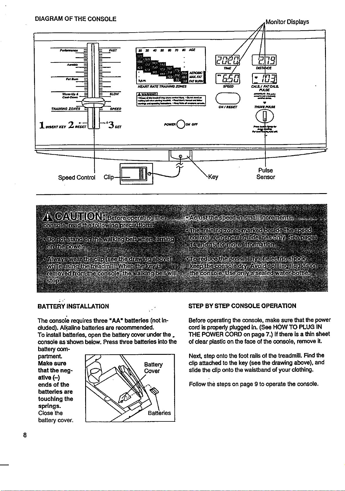
DIAGRAMOF THE CONSOLE Monitor Displays
m
J,,,_,,,_._.__= =._p=r
...--=- _.-
° • ,_.I_O_; I
JI_;.FAT
P!ffJ_T RATff _ _ES SPEED CAL_/ FATC4L_
-------.._...._..._
ON/RESET
POtt'l_O011 OFf
U
W8 P/JU_
Q
_M
Speed Control
\Key
Pulse
Sensor
8
BATTERY INSTALLATION
The console requires three "AA" batteries (not in-
cluded). Al.kalinebatteries are recommended.
To install batteries, open the battery cover under the.
console as shown below. Press three battedes intothe
battery com-
partment.
Make sure
that the neg-
ative (-)
ends of the
batteries are
touching the
springs.
Close the
battery cover.
Battery
_iedes
STEP BY STEP CONSOLE OPERATION
Before operating the console, make sure that the power
cord is propedyplugged in. (See HOw TO PLUG IN
THE POWER CORD on page 7.) Ifthere is a thin sheet
of clear plasticon the face ofthe console, remove it.
Next, step onto the foot rails of the treadmill. Find the
clip attached to the key (see the drawing above), and
slidethe cliponto the waistband of your clothing.
Follow the steps on page 9 to operate the console.
El
[]
B
B
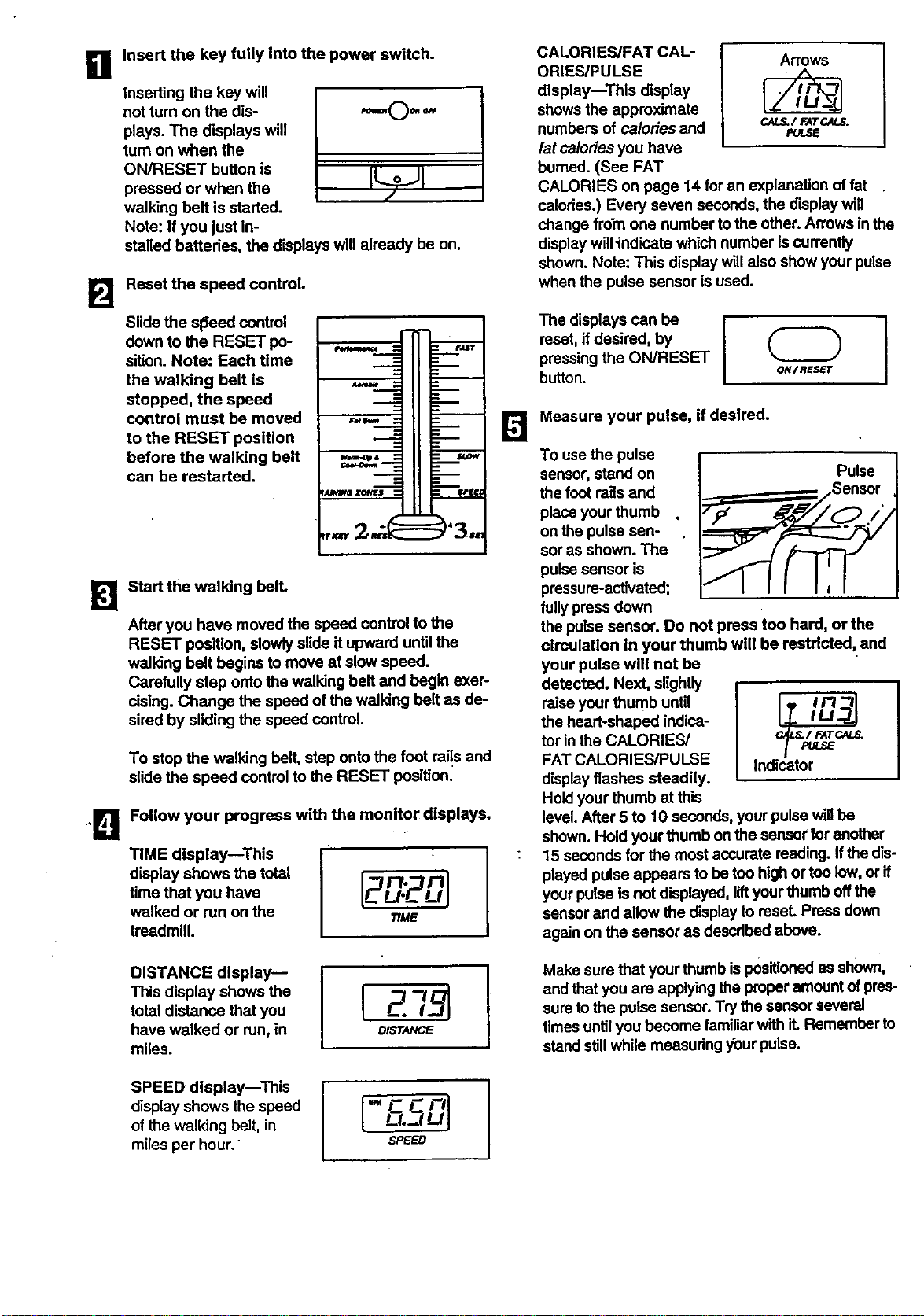
Insert the key fully into the power switch.
Inserting the key will
not turn on the dis-
plays. The displays will
turn on when the
ON/RESET button is
pressed or when the
walking belt is started.
Note: if you just in-
F_lll (_ (b/_1 ¢
stalled battedes, the displays will already be on.
Reset the speed control.
Slide the sl_=ed control
down to the RESET po-
sitlon. Note: Each time
the walking belt is
stopped, the speed
control must be moved
to the RESET position
before the walking belt
can be restarted.
Ji
Start the walking bell
After you have moved the speed control to the
RESET position, slowlyslide it upward until the
walking belt begins to move at slow speed.
Carefully step onto the walking belt and begin exer-
rising. Change the speed of the walking belt as de-
sired by sliding the speed control.
To stop the walking belt, step onto the foot rai!s and
slide the speed control to the RESET position.
Follow your progress with the monitor displays.
TIME display--This
display shows the total
time that you have
walked or run on the
treadmill.
Ft, Ft
TIME
I
DISTANCE display--
This display shows the
total distance that you
have walked or run, in
miles.
D/STANCE
l
CALORIES/FAT CAL-
ORIESIPULSE
display--This display
shows the approximate
numbers of ca/odes and
fat calories you have
burned. (See FAT
Arrow_
CAL_ / FATCALS.
PULS_
CALORIES on page 14 for an explanation of fat
calories.) Every seven seconds, the display will
change from one number to the other. Arrows inthe
displaywill"indicatewhich number iscurrently
shown. Note: This display will also show your pulse
when the pulse sensor is used.
The displays can be
reset, if desired, by
pressingthe ON/RESET
button.
ON/RESET
Measure your pulse, if desired.
To use the pulse
sensor, stand on Pulse
the foot railsand
place your thumb
on the pulse sen-
sor as shown. The
pulse sensor is
pressure-activated;
fully press down
the pulse sensor. Do not press too hard, orthe
circulation In your thumb wilt be rastrlcted, and
your pulse will not be
detected. Next, slightly
raise your thumb until _-_ /n----_lr/'7
the heart-shaped indica-
tor in the CALORIES/ c_s/_rpc, ms.
FAT CALORIES/PULSE indicator
/-
displayflashes steadily.
Hold your thumb at this
level. After 5 to 10 seconds, your pulse willbe
shown. Hold your thumb on the sensor for another
15 seconds for the most accurate reading. If the dis-
played pulse appears to be ton high ortoo low, or if
your pulse is not displayed, lift your thumb offthe
sensor and allow the display to reset. Press down
again on the sensor as described above.
Make sure that your thumb ispositionedas shown,
and that you are applying the proper amount ofpres-
sure to the pulse sensor. Try the sensor several
timesuntil you become familiar with it. Remember to
stand stillwhile measuring ybur pulse.
SPEED display--This
display shows the speed
of the walking belt, in
miles per hour.
" _ C Ftl
0._1uj
SPEWED
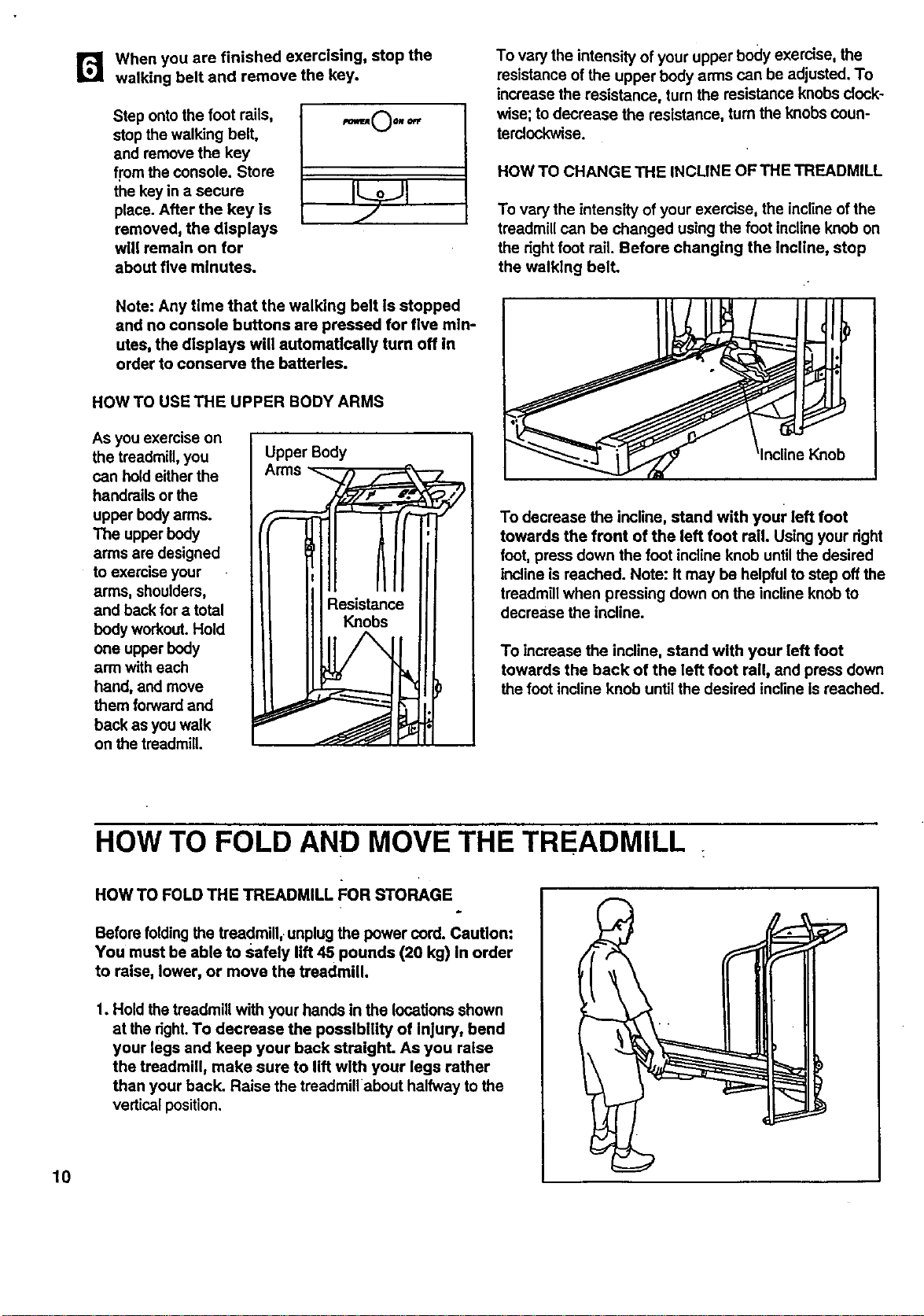
r_ When you are finished exercising, stop the
walking belt and remove the key.
Step ontothe foot rails,
stopthe walking belt,
and remove the key
from the console. Store
the key in a cecum
place. After the key Is
removed, the displays
will remain on for
about five minutes.
Note: Any time that the walking belt is stopped
and no console buttons are pressed for five mln-
utes, the displays will automatically turn off in
order to conserve the batteries.
HOW TO USE THE UPPER BODY ARMS
As you exercise on
the treadmill,you
can hold eitherthe
handrails or the
upper bodyarms.
The upper body
arms are designed
to exercise your
arms, shoulders,
and back for a total
body workout.Hold
one upper body
arm with each
hand, and move
them forward and
back as you walk
on the treadmill.
UpperBody
To van/the intensity of your upper body exerdse, the
resistance of the upper body arms can be adjusted. To
increase the resistance, turn the resistance knobs clock-
wise; to decrease the resistance, turn the knobs Coun-
terclockwise.
HOW TO CHANGE THE INCUNE OF THE TREADMILL
To van/the intensity of your exemise, the incline ofthe
treadmill can be changed using the foot incline knob on
the dght foot rail. Before changing the Incline, stop
the walking belt.
To decrease the incline, stand with your left foot
towards the front of the left foot rail. Using your dght
foot, press down the foot incline knob untilthe desired
incline isreached. Note: Itmay be helpful to step off the
treadmill when pressing down on the incline knobto
decrease the incline.
To increase the incline, stand with your left foot
towards the back of the left foot rail, and press down
the foot incline knob until the desired incline Is reached.
HOW TO FOLD AND MOVE THE TREADMILL
HOW TO FOLD THE TREADMILL I=OR STORAGE
Before foldingthe treadmill, unplug the power cord. Caution:
You must be able to safely lift 45 pounds (20 kg) In order
to raise, lower, or move the treadmill.
1. Hold the treadmill with your hands in the locations shown
at the right.To decrease the possibility of Injury, bend
your legs and keep your back straight. As you raise
the treadmill, make sure to lift wlth your legs rather
than your back. Raise the treadmill about halfway to the
vertical position.
10
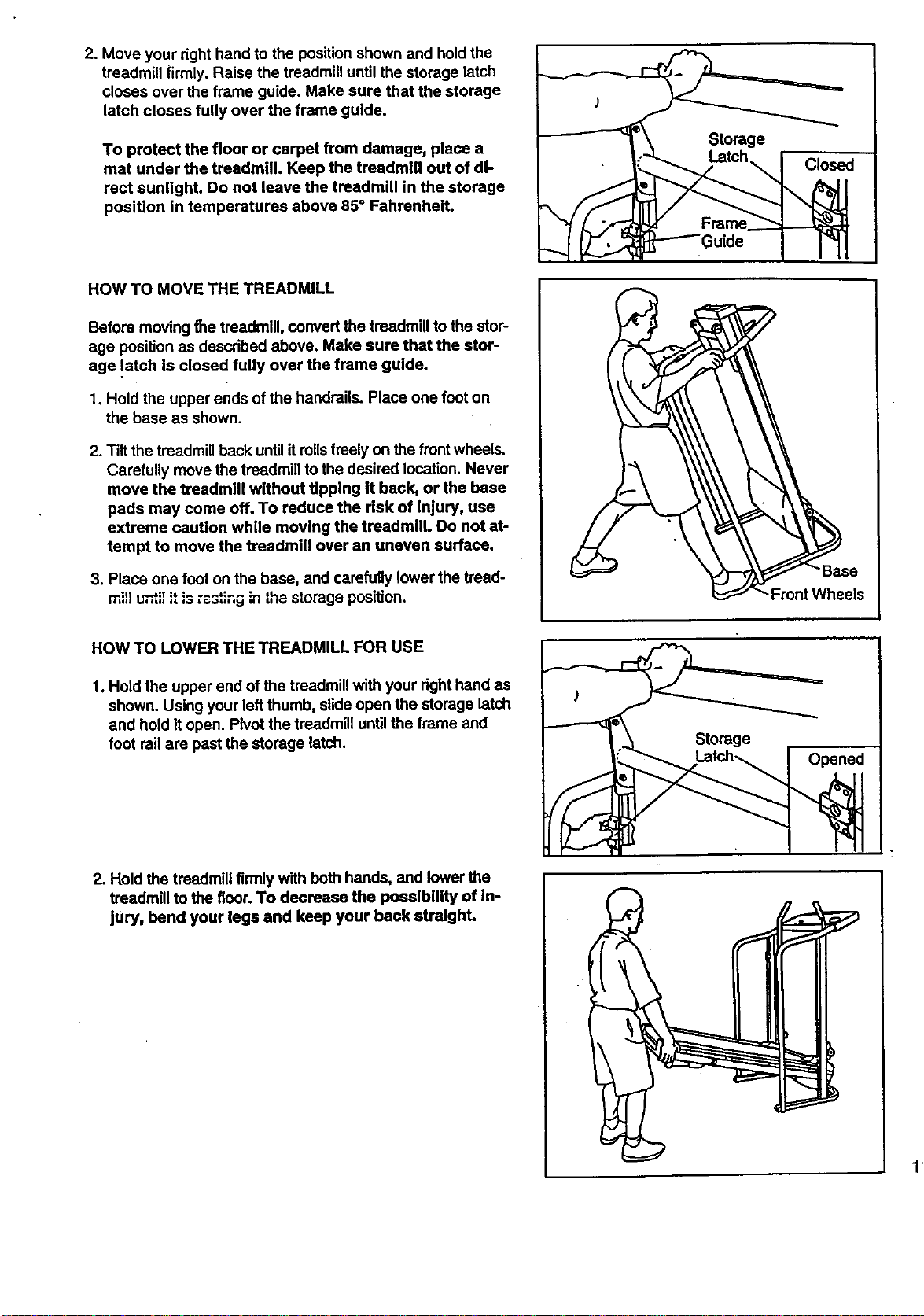
2. Move your right hand to the position shown and hold the
treadmill firmly. Raise the treadmill until the storage latch
closes over the frame guide. Make sure that the storage
latch closes fully over the frame guide.
To protect the floor or carpet from damage, place a
mat under the treadmill. Keep the treadmill out of di-
rect sunlight. Do not leave the treadmill in the storage
position in temperatures above 85" Fahrenheit.
HOW TO MOVE THE TREADMILL
Before moving the treadmill, convert the treadmill to the stor-
age position as described above. Make sure that the stor-
age !atch Is closed fully over the frame guide.
1. Hold the upper ends of the handrails. Place one foot on
the base as shown.
2. Tilt the treadmill back until itmils freely on the front wheels.
Carefully move the treadmill to the desired location. Never
move the treadmlU without tipping it back, or the base
pads may come off. To reduce the dsk of injury, use
extreme caution while moving the treadmilL Do not at-
tempt to move the treadmill over an uneven surface.
3. Place one foot on the base, and carefully lower the tread-
mill until _tis _3_ng in tha storage position.
HOW TO LOWER THE TREADMILL FOR USE
1. Hold the upper end of the treadmill with your right hand as
shown. Using your left thumb, slide open the storage latch
and hold it open. Pivot the treadmill until the frame and
foot rail are past the storage latch.
2. Hold the treadmill firmlywith both hands, and lower the
treadmill to the floor.To decrease the poealbllity of in-
JUry, bend your legs and keep your back straight.
e
"_Front Wheels
Opened
11
TROUBLE-SHOOTING
Most treadmill problems can be solved by following the simple steps below. Find the symptom that ap-
pUes, and follow the steps listed, if further assistance is needed, call our toll-free HELPLINE at 1-800-736-
6879, Monday through Saturday, 7 a.m. until 7 p.m. Central Time (excluding holidays).
1. SYMPTOM: THE POWER DOES NOT TURN ON
a. Make sure that the power cord is plugged into a surge protector, and that the surge protector is plugged into
a properly grounded outlet. (See HOW TO PLUG IN THE POWER CORD on page 7.) Use only a UL-listed
surge protector, rated at 15 arnps, with a 14-gauge cord of five feet or less in length.
b. After the power cord has been plugged !n, make sure that the key is tully inserted into the console. (See step
1 on page 9.)
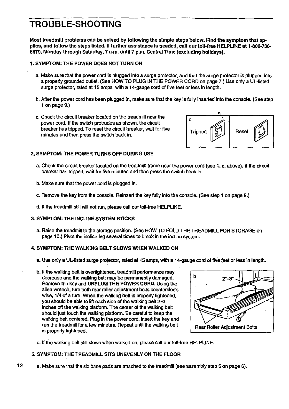
c. Check the cimuit breaker located on the treadmill near the
power cord. Ifthe switch protrudes as shown, the circuit
breaker has tripped. To reset the circuit breaker, wait for five
minutes and then press the switch back in.
Tripped
Reset
2. SYMPTOM: THE POWER TURNS OFF DURING USE
a. Check the circuit breaker located on the treadmill frame near the power cord (see 1. c. above). If the circuit
breaker has tripped, wait for five minutes and then press the switch back in.
b. Make sure that the power cord is plugged in.
c. Remove the key from the console. Reinsert the key fully into the console. (See step I on page 9.)
d. If the treadmill stillwill not run, please call our toll-free HELPLINE.
3. SYMPTOM: THE INCUNE SYSTEM STICKS
a. Raise the treadmiUto the storage position. (See HOW TO FOLD THE TREADMILL FOR STORAGE on
page 10.) Pivot the incline leg several times to break in the incline system.
4. SYMPTOM: THE WALKING BELT SLOWS WHEN WALKED ON
a. Use only a UL-listed surge pro.tector,rated at 15 amps, with a 14-gauge cord of fl0e feet or less in length.
b. If the walking belt is 0vertightened, treadmill performance may
decrease and the walking belt may be permanently damaged,
Remove the key and UNPLUG THE POWER CqgRD.Using the
allen wrench, turn both rear roller adjustment bolts counterclock-
wise, 1/4 of a turn. When the walking belt is properly tightened,
you should be able to lifteach side of the walking belt 2--3
inches off the walking platform. The center of the walking belt
should just touch the walking platform. Be careful to keep the
walking belt centered. Plug in the power cord, insert the key and
run the treadmill for a few minutas. Repeat until the walking belt
is properly tightened.
Rear Roller Adjustment Bolts
c. If the walking belt stillslows when walked on, please call our toll-free HELPUNE.
5. SYMPTOM: THE TREADMILL SITS UNEVENLY ON THE FLOOR
12 a. Make sure that the Sixbase pads are attached to the treadmill (see assembly step 5 on page 6).
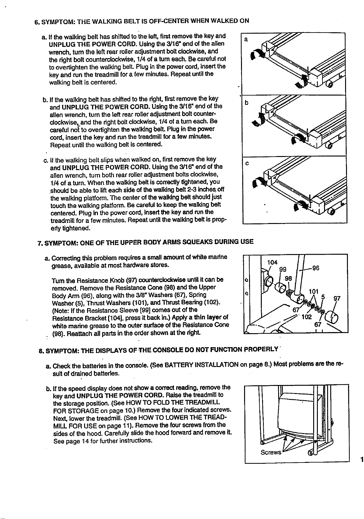
6.SYMPTOM:THEWALKINGBELTISOFF-CENTERWHENWALKEDON
a. If the walking belt has shifted to ihe left, first remove the key and
UNPLUG THE POWER CORD. Using the 3/16" end ofthe allen
wrench, turn the left rear roller adjustment belt clockwise, and
the dght bolt counterclockwise, 1/4 of a tum each. Be careful not
to overtightan the walking belt. Plug in the power cord, insert the
key and run the treadmill for a few minutes. Repeat untilthe
walking belt is centered.
b. Ifthe walking belt has shifted to the right, first remove the key
and UNPLUG THE POWER CORD. Using the 3/16" end of the
allen wrench, turn the left rear roller adjustment boltcounter-
clockwise, and the right bolt clockwise, 1/4 of a turn each. Be
careful not'to overtighten the walking belt. Plug in the power
cord, insert the key and run the treadmill for a few minutes.
Repeat until the walking belt is centered.
c. If the walking belt slips when walked on, first remove the key
and UNPLUG THE POWER CORD. Using the 3/16" end of the
allen wrench, turn both rear roller adjustment bolts clockwise,
1/4 of a turn. When the walking belt is correctly tightened, you
•should be able to lift each side of the walking belt 2-3 inchesoff
the walking platform. The center of the walking belt shouldjust
touch the walking platform. Be careful to keep the walking belt
centered. Plug in the power cord, insert the key and runthe
treadmill for a few minutes. Repeat until the walking belt is prop-
edy tightened.
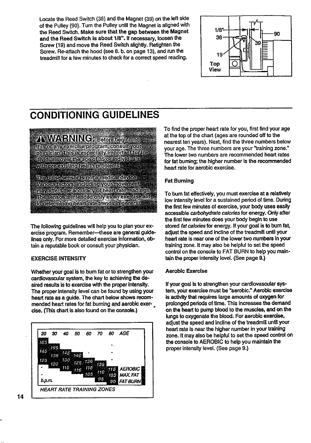
7. SYMPTOM: ONE OF THE UPPER BODY ARMS SQUEAKS DURING USE
a. Correcting this problem requires a small amount of white madne
grease, available at most hardware stores.
Tum the Resistance Knob (97) counterclockwise until it can be
removed. Remove the Resistance Cone (98) and the Upper
Body Arm (96), along with the 3/8" Washers (67), Spdng
Washer (5), Thrust Washers (101), and Thrust Beadng (102).
(Note: If the Resistance Sleeve [99] comes out ofthe
Resistance Bracket [104], press it back in.) Apply a thin layer of
white marine grease to the outer surface of the Resistance Cone
(98). Reattach all parts in the order shown at the dghL
104
99
67
8. SYMPTOM: THE DISPLAYS OF THE CONSOLE DO NOT FUNCTION PROPERLY
a. Check the battedes in the console. (See BATI'ERY INSTALLATION on page 8.) Most problems are the re-
sult of drained batteries.
b. Ifthe speed display does not show a correct reading, remove the
key and UNPLUG THE POWER CORD. Raise the treadmill to
the storage position. (See HOW TO FOLD THE TREADMILL
FOR STORAGE on page 10.) Remove the four indicated screws.
Next, lower the treadmill. (See HOW TO LOWER THE TREAD-
MILL FOR USE on page 11). Remove the four screws from the
sides of the hood. Carefully slide the hood forward and remove it.
See page 14 for further instructions.
Screws
1:
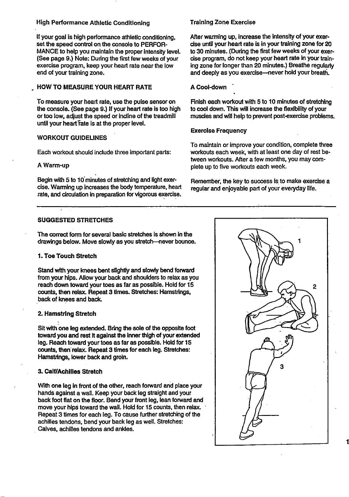
Locate the Reed Switch (38) and the Magnet (39) on the left side
of the Pulley (90). Turn the Pulley until the Magnet is aligned with
the Reed Switch. Make sure that the gap between the Magnet
and the Reed Switch is about 118". If necessary, loosenthe
Screw (19) and move the Reed Switch slightly. Retighten the
Screw. Re-attach the hood (see 8. b. on page 13), and nJnthe
treadmill for a few minutes tocheck for a correct speed reading.
1/8"-_1--
38--
197 __
Top (_)
View --
(--
_90
14
CONDITIONING GUIDELINES
The following guidelines will help you to planyour ex-
emise program. Remember--these are general guide-
lines only. For more detailed exemise information, ob-
tain a reputable book or consult your physician.
EXERCISE INTENSITY
Whether your goal is to bum fat or to strengthen your
cardiovascularsystem, the key to achieving the de-
sired resultsisto exercise with the proper intensity.
The properintensity level can be found by using your
heart rate as a guide. The chart below shows recom-
mended heart rates for fat burningand aerobic exer-,
cise. (Thls chart is also found on the console.)
b.p.m.
HEART RATE TRAINING ZONES
AGE
AEROBIC
MAX. FAT
FATBUR_
To find the proper heart rate for you, first find your age
at the top of the chart (ages are rounded off to the
nearest ten years). Next, find the three numbers below
your age. The three numbers are your "training zone."
The lower two numbers are recommended heart rates
for fat burning;the higher number is the recommended
heart rate for aerobic exercise.
Fat Burning
To bum fat effectively,you must exercise at a relatively
low intensitylevel for a sustained period of time. During
the firstfew minutes of exercise, your body uses easily
accessible carbohydrate calories for energy. Only after
the firstfew minutes does your body begin to use
stored fat calories for energy. If your goal isto bum fat,
adjustthe speed and incline of the treadmill until your
heart rate is near one of the lower two numbers in your
training zone. It may also be helpful to set the speed
controlon the console to FAT BURN to help you main-
taln the proper intensity level. (See page 9.)
Aerobic Exercise
Ifyour goal is to strengthen your cardiovascular sys-
tem, your exemise must be "aerobic." Aerobic exercise
isactivity that requires large amounts ofoxygen for
prolonged pedods of time. This increases the demand
on the bead to pump blood to the muscles, and on the
lungs to oxygenate the blood. For aerobic exercise,
adjust the speed and incline ofthe treadmill until your
heart rate isnear the higher number in your training
zone. It may also be helpful to set the speed controlon
the console toAEROBIC to help you maintain the
proper intensitylevel. (See page 9.)
High Performance Athletic Conditioning
If your goal is high performance athletic conditioning,
set the speed control on the console to PERFOR-
MANCE to help you maintain the proper intensity level.
(See page 9.) Note: Dudng the first few weeks of your
exercise program, keep your head rate near the low
end of your training zone.
o HOW TO MEASURE YOUR HEART RATE
To measure your heart rate, use the pulse sensor on
the console. (See page 9.) If your head rate istoo high
or too low, adjust the speed or inclineof the treadmill
until your headTate is at the proper level.
WORKOUT GUIDELINES
Each workout should include three important pads:
A Warm-up
Begin with 5 to 10minutes of stretchingand lightexer-
cise. Warming up increases the body temperature, head
rate, and drculatlon in preparation for vigorousexercise_
Training Zone Exercise
After warming up, increase the intensity of your exer-
rise until your head rate is in your training zone for 20
to 30 minutes. (Dudng the firstfew weeks of your exer-
cise program, do not keep your head rate in your train-
ing zone for longer than 20 minutes.) Breathe regula.dy
and deeply as you exeroise--never hold your breath.
A Cool-down "
Finisheach workout with 5 to 10 minutes of stretching
to cool down. This will increase the flexibility ofyour
muscles and willhelp to prevent post-exerclse problems.
Exercise Frequency
To maintain or improve your condition, complete three
workouts each week, with at least one day of rest be-
tween workouts. After a few months, you may com-
plete up to five workouts each week.
Remember, the key to success iSto make exercise a
regular and enjoyable part of your everyday life.
SUGGESTED STRETCHES
The correct form for several basic stretches is shown In the
drawings below. Move slowly as you stretch--never bounce.
1. Toe Touch Stretch
Stand with your knees bent slightlyand slowly bend forward
from your hips. Allow your back and shoulders to relax as you
reach down toward your toes as far as possible. Hold for 15
counts, then relax. Repeat 3 times. Stretches: Hamstrings,
back of knees and back.
2. Hamstring Stretch
Sit with one leg extended. Bring the sole ofthe opposite foot
toward you and rest It against the inner thigh ofyour extended
leg. Reach toward your toes as far as possible. Hold for 15
counts, then_relax. Repeat 3 times for each leg. Stretches:
Hamstrings, lower back and groin.
3, Calf/Achilles Stretch
With one leg in front of the other, reach forward and place your
hands against a wall. Keep your back leg straight and your
back foot fiat on the floor. Bend your front leg, lean forward and
move your hips toward the wall. Hold for 15 counts, then relax.
Repeat 3 times for each leg. To cause fudher stretchingof the
achilles tendons, bend your back leg as well. Stretches:
Calves, achilles tendons and ankles.
Remove this HARDWARE IDENTIFICATION CHART,
EXPLODED DRAWING and PART LIST from the user's
manual. Save this page for future reference.
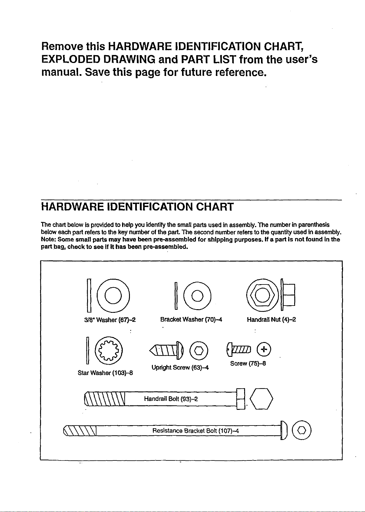
HARDWARE IDENTIFICATION CHART
The chart below is provided to help you identity the small pads used in assembly. The number in parenthasis
below each part refers tothe key number of the part. The second number refers to the quantity used In assembly.
Note: Some small parts may have been pre-assembled for shipping purposes. If a part is not found in the
part bag, check to see if it has been pre-assembled.
3/8" Washer (67)-2
H@
Star Washer (103)-8
H
Bracket Washer (70)-4
Upright Screw (63)-4
Handrail Nut (4)-2
_\_ HandrailBolt(93)-2
_XXXXXI ' Resistance Bracket Bolt (107)-4
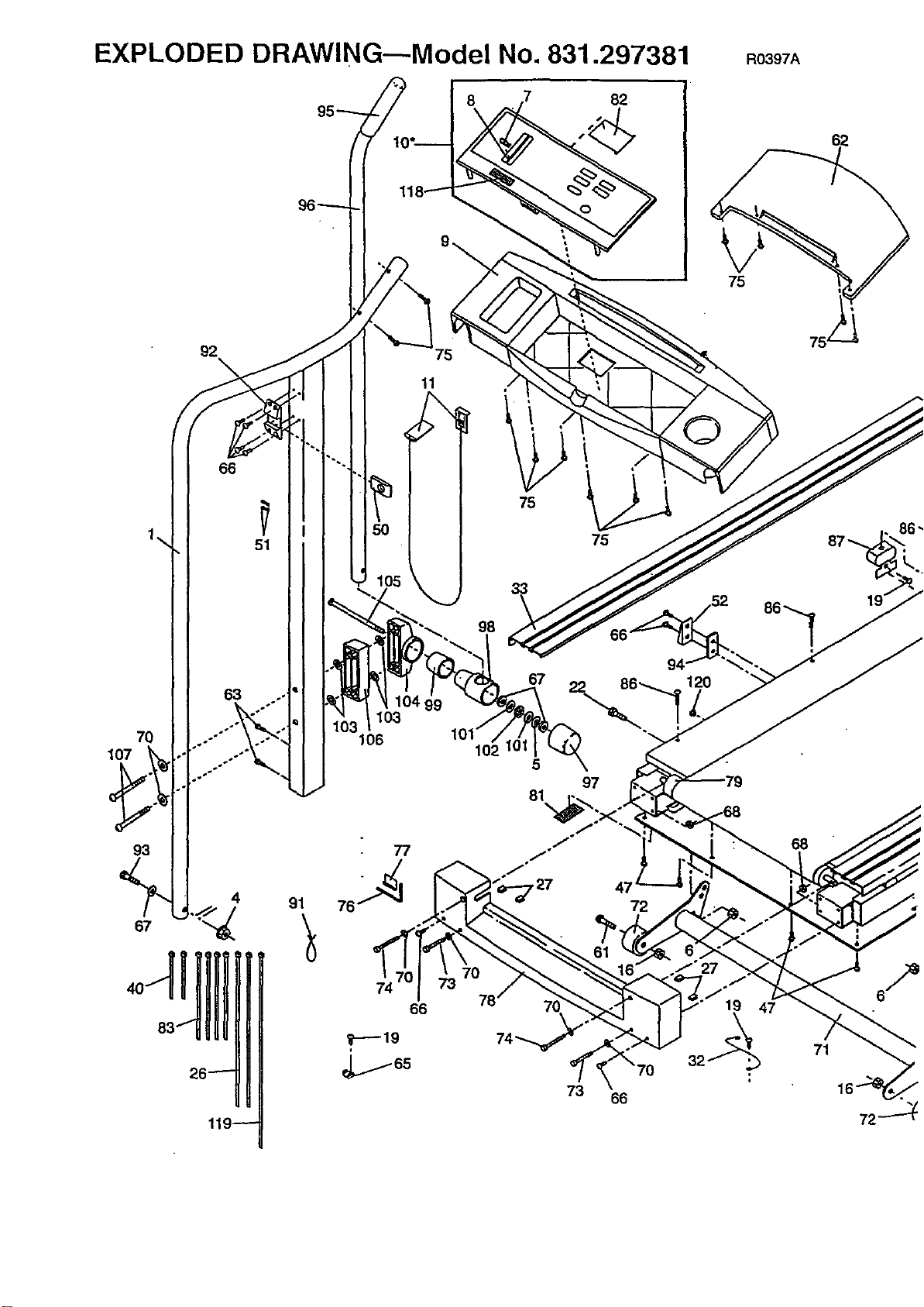
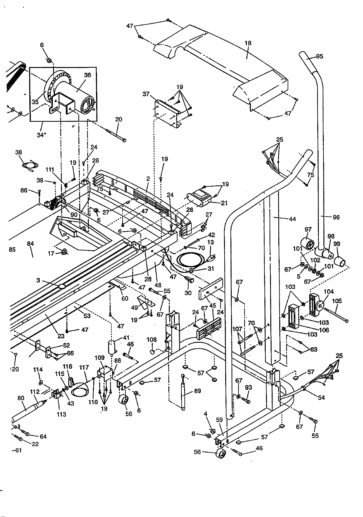
EXPLODED DRAWING---Model No. 831.297381 RO397A
8 82
75
92
\
66
63
70
107
93
4
67 "_
26_
119--
51
91
103
106
• 77
74
66
7_
11
75
98
102
5
97
81
J_
f°
,27 47 _
72
78 7C
74_.
73 66
120
19
68
71
72_
85
"T
_20
6
\,
4,¢,
38
"_ 111
8O
3
114
112.
"22
i
L----47
23
116
115
43
113
2O
24
28
109
117
110
"-..47
6O
47
19
25
19
2
19
46
56 6
48
108
• ._19
._21
27
3O
u
4
97
5
67
103
i
93
t
.57 55
98
"54
99
.°
104
105
25
-61 -.,_ 46
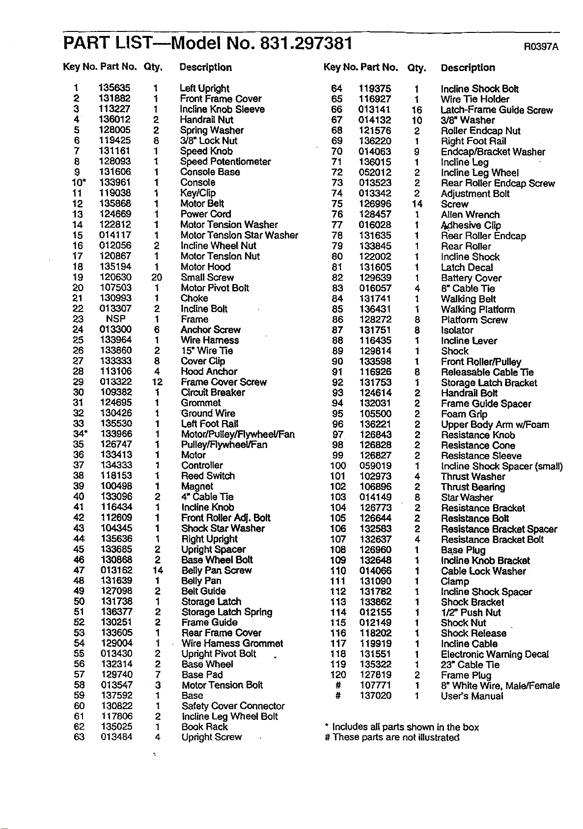
PART LISTmModel NO. 831.297381 R0397A
Key No. Part No. Oty,
Description Key No. Part No. Qty.
1 135635 1 LeftUpright 64 119375
2 131882 1 Front Frame Cover 65 116927
3 113227 1 InclineKnob Sleeve 66 013141
4 136012 2 Handrail Nut 67 014132
5 128005 2 SpringWasher 68 121576
6 119425 8 3/'8"Lock Nut 69 136220
7 131161 1 Speed Knob 70 014063
8 128093 1 Speed Potentiometer 71 136015
9 131606 1 Console Base 72 052012
10" 133961 1 Console 73 013523
11 119038 1 Key/Clip 74 013342
12 135868 1 Motor Belt 75 126996
13 124669 1 Power Cord 76 128457
14 122812 1 Motor Tension Washer 77 016028
15 014117 1 Motor Tension Star Washer 78 131635
16 012056 2 InclineWheel Nut 79 133845
17 120867 1 Motor Tension Nut 80 122002
18 135194 1 Motor Hood 81 131605
19 120630 20 Small Screw 82 129639
20 107503 1 Motor Pivot Bolt 83 016057
21 130993 1 Choke 84 131741
22 013307 2 InclineBolt 85 136431
23 NSP 1 Frame 86 128272
24 013300 6 Anchor Screw 87 131751
25 133964 1 Wire Harness 88 116435
26 133860 2 15"Wire Tie 89 129814
27 133333 8 Cover Clip 90 133598
28 113106 4 Hood Anchor 91 116926
29 013322 12 Frame Cover Screw 92 131753
30 109382 1 CircuitBreaker 93 124614
31 124695 1 Grommet 94 132031
32 130426 1 Ground Wire 95 105500
33 135530 1 Left Foot Rail 96 136221
34* 133966 1 Motor/Pulley/Flywheel/Fan 97 126843
35 126747 1 Pulley/Flywheel/Fan 98 126828
36 133413 1 Motor 99 126827
37 134333 1 Controller 100 059019
38 118153 1 Reed Switch 101 102973
39 100498 1 Magnet 102 106896
40 133096 2 4" Cable Tie 103 014149
41 116434 1 InclineKnob 104 126773
42 112609 1 Front RollerAdj. Bolt 105 126644
43 104345 1 Shock Star Washer 106 132583
44_ 135636 1 Right Updght 107 132637
45 133685 2 UprightSpacer 108 126960
46 130868 2 Base Wheel Bolt 109 132648
47 013162 14 BellyPan Screw 110 014066
48 131639 1 BeUyPan 111 131090
49 127098 2 Belt Guide 112 131782
50 131738 1 Storage Latch 113 133862
51 136377 2 Storage Latch Spring 114 012155
52 130251 2 Frame Guide 115 012149
53 133605 1 Rear Frame Cover 116 118202
54 129004 1 Wire Harness Grommet 117 119919
5-5 013430 2 UprightPivot Bolt 118 131551
56 132314 2 Base Wheel 119 135322
57 129740 7 Base Pad 120 127819
58 013547 3 Motor Tension Bolt # 107771
59 137592 1 Base # 137020
60 130822 1 Safety Cover Connector
61 117806 2 Incline Leg Wheel Bolt
62 135025 1 Book Rack
63 013484 4 Upright Screw
Description
1 Incline Shock Bolt
1 Wire Tie Holder
16 Latch-Frame Guide Screw
10 3/8" Washer
2 Roller Endcep Nut
1 Right Foot Rail
9 Endcap/Bracket Washer
1 Incline Leg
2 Incline Leg Wheel
2 Rear Roller Endcap Screw
2 Adjustment Bolt
14 Screw
1 Allen Wrench
1 ,_lhesive Clip
1 Rear Roller Endcap
1 Rear Roller
1 Incline Shock
1 Latch Decal
1 Battery Cover
4 8"Cable Tie
1 Walking Belt
1 Walking Platform
8 Platform Screw
8 Isolator
1 Incline Lever
1 Shock
1 Front Roller/Pulley
8 Releasable Cable Tie
1 Storage Latch Bracket
2 Handrail Bolt
2 Frame Guide Spacer
2 Foam Grip
2 Upper Body Arm w/Foam
2 Resistance Knob
2 Resistance Cone
2 Resistance Sleeve
1 Incline Shock Spacer (small)
4 Thrust Washer
2 Thrust Beadng
8 Star Washer
2 Resistance Bracket
2 Resistance Bolt
2 Resistance Bracket Spacer
4 Resistance Bracket Bolt
1 Base Plug
1 Incline Knob Bracket
1 Cable Lock Washer
1 Clamp
1 Incline Shock Spacer
1 Shock Bracket
1 1/2" Push Nut
1 Shock Nut
1 Shock Release
1 Incline Cable
1 Electronic Warning Decal
1 23" Cable Tie
2 Frame Plug
1 8" White Wr_re,Male/Female
1 User's Manual
* Includes all parts shownin the box
# These parts are not illustrated
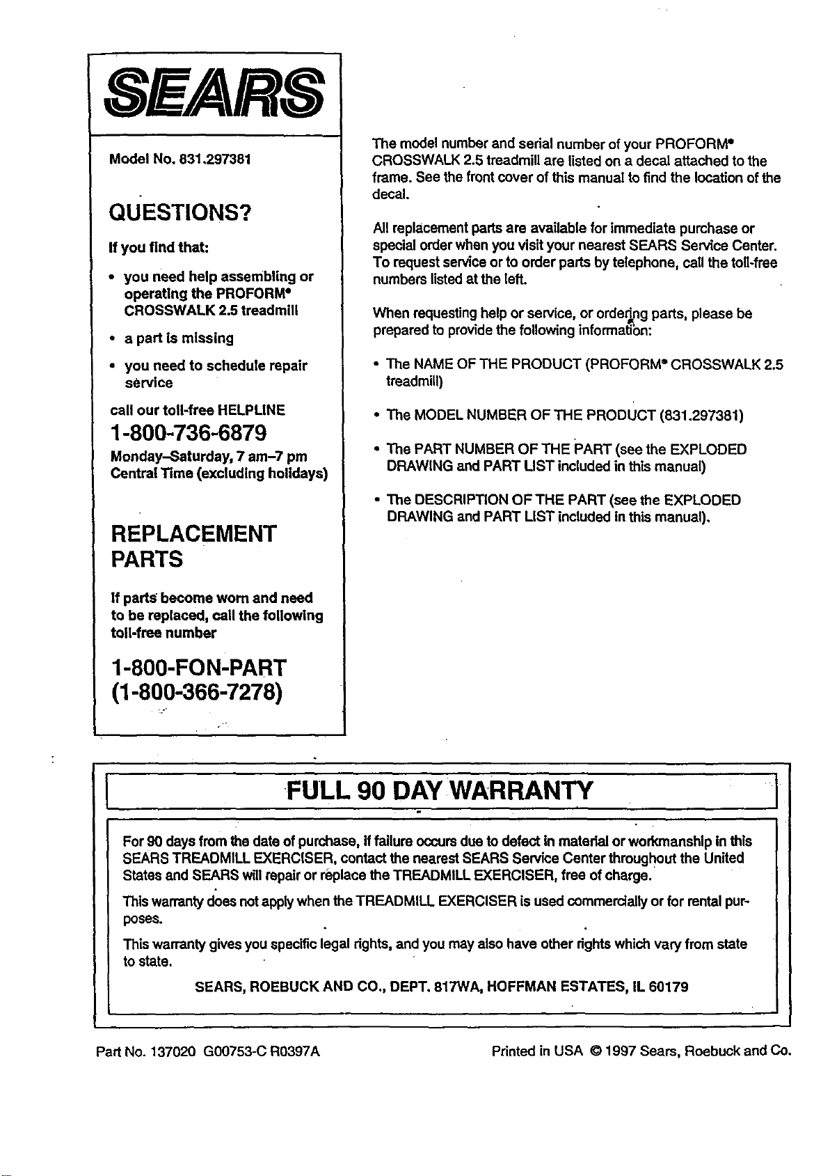
ModelNo.831,297381
QUESTIONS?
If you find that:
• you need help assembling or
operating the PROFORM"
CROSSWALK 2.5 treadmill
• a part is missing
• you need to schedule repair
service
call our toll-free HELPLINE
1-800-736-6879
Monday-Saturday, 7 am-7 pm
Central Time (excluding holidays)
REPLACEMENT
PARTS
If pads become worn and need
to be replaced, caU the following
toil-free number
1-800-FON-PART
(1-800-366-7278)
The model number and sedai number of your PROFORM =
CROSSWALK 2.5 treadmill are listed on a decal attached to the
frame. See the frontcover of this manual to find the location of the
decal.
All replacement parts are available for immediate purchase or
special order when you visit your nearest SEARS Service Center•
To request service or to order pads by telephone, call the toll-free
numbers listedat the left.
When requesting help or service, or ordering parts, please be
• JR
prepared to pro_de the following informatibn:
• The NAME OF THE PRODUCT (PROFORM ®CROSSWALK 2.5
treadmill)
• The MODEL NUMBER OF THE PRoDUcT (831.297381)
• The PART NUMBER OF THE PART (see the EXPLODED
DRAWING and PART UST included in this manual)
• The DESCRIPTION OFTHE PART (see the EXPLODED
DRAWING and PART LIST included in this manual),
FULL 90 DAY WARRANTY
For 90 days from the date of purchase, iffailure occursdue to defect in matedai or workmanship in this
SEARS TREADMILL EXERCISER, contact the nearest SEARS Service Center throughout the United
States and SEARS will repair or replace the TREADMILL EXERCISER, free of charge.
This warranty does notapply when the TREADMILL EXERCISER isused commercially or for rental pur-
poses.
This warranty gives you specific legal dghts, and you may also have other rights which vary from state
to state•
SEARS, ROEBUCK AND CO•, DEPT. 817WA, HOFFMAN ESTATES, IL 60179
Part No. 137020 G00753-C R0397A Printed in USA © 1997 Sears, Roebuck and Co.