Loading ...
Loading ...
Loading ...
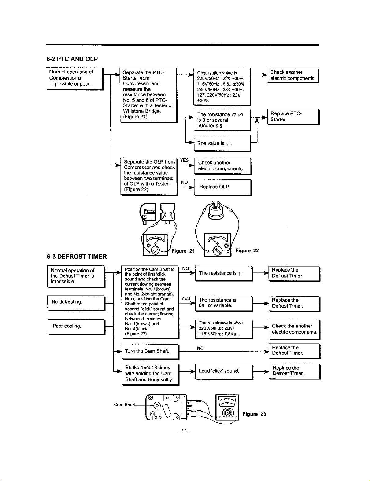
6-2 PTC AND OLP
k
Normal operation of L
Compressor is
/
impossible or poor.
6-3 DEFROST TIMER
t
Separate the PTC-
Starter from
I
Compressor and
measure the
resistance between
No. 5 and 6 of PTC-
Starter with a Tester or
Whistone Bridge. -_
(Figure 21)
i [
Observation valueis I _1
220V,'50Hz : 225 -+30%
115V/60Hz : 6.85 -+30%
240V/50Hz :335 -+30%
127,220VI60Hz : 225
-+30%
The resistance value
is Oor several
r
hundreds _ .
The value is ; -.
I Separate the OLP from _ Check another
Compressor and check _ electric components. I
the resistance value _ I
I
between two terminals I r
of OLP with a Tester. _ I
(Figure 22) _ Replace OUR
l
@ure
II
Normal operation of I_
the Defrost Timer is -_
/mposs b e.
No defrosting. F
Poor cooling, t--
Position the Cam Shaft to
the point of first 'click'
sound and check the
current flowing between
terminals No. 1(brown)
and No. 2(bright orange).
Next, posit}on the Cam
Shaft to the point of
second "click" sound and
check the current flowing
between terminals
No. 1(brown) and
No. 4(black)
(Figure 23),
--_ The resistance is i ~ i_i
._The resistanceis I_
0§ or variable.
_b_ The resistance isabout
220V/50Hz : 20K§
115V/60Hz : 7.eKS ,
---_ Ture the Cam Shaft. I NO }_
-_ with holding the Cam Loud 'click' sound.
Shaft and Body softly.
Check another Ielectric components.
Replace PTC-
Starter
Replace the
DefrostTimer.
Replacethe
Defrost Timer,
Check the another
electric components.
Replace the
Defrost Tiraer.
Replace the
Defrost Timer.
I
I
I
I
-11 -
Figure 23
Loading ...
Loading ...
Loading ...