LVL113A
09/16
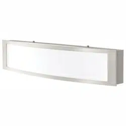
LED VANITY
Star-headed
Screwdriver
Pliers
Hammer
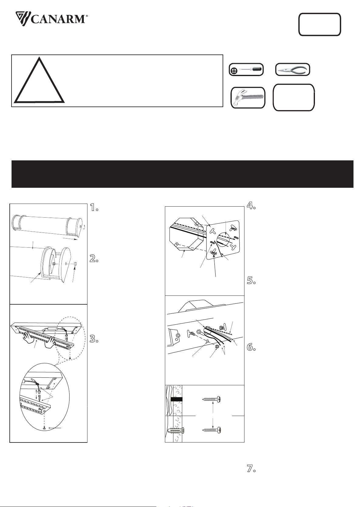
TOOLS AND MATERIALS REQUIRED:
!
INSTRUCTIONS PERTAINING TO RISK OF FIRE OR INJURY TO PERSONS
READ ALL INSTRUCTIONS
IMPORTANT SAFETY
INSTRUCTIONS
SAVE THESE INSTRUCTIONS
SAFETY PRECAUTIONS:
1. TURN OFF ELECTRICAL POWER BEFORE STARTING INSTALLATION OF LIGHT FIXTURE.
2. THIS PRODUCT MUST BE INSTALLED IN ACCORDANCE WITH THE APPLICABLE INSTALLATION CODE BY A
PERSON FAMILIAR WITH THE CONSTRUCTION AND OPERATION OF THE PRODUCT AND THE HAZARDS
INVOLVED.
3. THIS FIXTURE IS DESIGNED FOR 120 VOLT CIRCUIT. IF UNSURE ABOUT WIRING, CONSULT AN ELECTRICIAN.
WARNING: DO NOT CONNECT FIXTURE TO DIMMER CIRCUIT.
4. THIS FIXTURE MUST BE GROUNDED PROPERLY. CONNECT THE GROUND WIRES (BARE COPPER OR GREEN) TO
THE AC SUPPLY GROUND WIRE (BARE COPPER OR GREEN) OR GROUND SCREW IN THE ELECTRICAL OUTLET
BOX. IF GROUND WIRE IS NOT AVAILABLE IN YOUR AC SUPPLY WIRE SYSTEM, PLEASE CONSULT A QUALIFIED
ELECTRICIAN BEFORE PROCEEDING THE ELECTRICAL CONNECTION.
Wiring supplies
as required by
local electrical
code
NOTE: Product may not look exactly as shown in figures.
QUESTIONS OR CONCERNS CONTACT CANARM AT:
1-800-265-1833 (English) / 1-800-567-2513 (French)
Monday through Friday 8:00 AM to 5:00 PM E.S.T.
Imported By: CANARM LTD., 2157 Parkedale Ave., Brockville, Ontario, K6V 5V6, Tel: (613) 342-5424, Fax: (800) 263-4598
1. Remove the screw on the
both sides.
2. Slide the decorate ring
from both sides. Remove the
diffuser from the fixture.
3. Remove the front cover
by loosening the screw.
Disconnect the male and
female wires from the front
cover to the male and female
wires in the back plate.
4. Remove knockouts (on the mounting
plate) corresponded to the mounting
screws on the electrical box.
Install the 2 machine screws to the
mounting plate. Be sure the 2 machine
screws are parallel to the floor. Pull wires
from electrical box and tighten the
mounting plate to the electrical box using
the 2 screws supplied by the electrical
box.
5. Tighten the back plate over the
mounting plate by the star washers and
nuts provided. Ensure the back plate is
level to the floor. Additional support may
be required for fixtures longer than 30”
.
Position the fixture and add wood screws
(one on each side) for the wooden studs
or plastic wall anchor and wood screws
for dry wall.
6. Connect the ground wires to the
ground screw located near the centre
knockout of the electrical box or the
ground wire in the electrical box. Connect
the black wire from the fixture to the
black wire from the electrical box.
Connect the white wire from the fixture to
the white wire from the electrical box.
Once wires are connected, carefully tuck
wires and marretts into the electrical box.
Alternatively, an outlet box is not normally
required when the electrical leads are
entering the fixture from the back and
supply wiring has a minimum of 90 deg. C
temperature rating. Before installing
always consult your local Electrical Safety
Authority or qualified
electrician if you are unfamiliar with local
Electrical Standards.
7. Reverse the process of Step 3, 2, 1 to
install the fixture.
White Diffuser
Decorative
ring
Decorative
end screw
Mounting plate
Electrical
Box
Screw
Electrical
Box
Front cover
Machine
Screw
Star
washer
House supply
Ground wire
Fixture
Ground
wire
Fixture
Ground
wires
White
Black
House supply
Ground wire
INSTALLATION:
Nut
Screw
Wires
Wood Screw