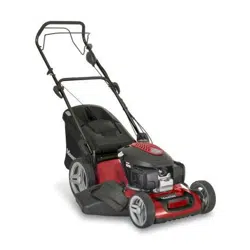
Mountfield SP485 HW V Lawn mower

Operator’s Manual - Page 34

For SP485 HW V. Series: MP1 504, MP1 554

PDF File Manual, 58 pages, Read Online | Download pdf file

SP485 HW V photo
Loading ...
Loading ...
Loading ...



44. 
hands or feet near or under the opening of the cutting

OPERATING INSTRUCTIONS
For information on the engine and the battery (if sup-
plied), read the relevant owner manuals.
NOTE – The number which precedes each paragraph
links the references in the text to the respective illus-
trations (listed on page iii and following pages).
1. COMPLETE ASSEMBLY
NOTE The machine can be supplied with some parts al-
ready assembled.
WARNING! Unpacking and completing the assem-
bly should be done on a flat and stable surface, with
enough space for moving the machine and its packag-
ing, always making use of suitable equipment.
Disposal of the packaging should be done in accord-
ance with the local regulations in force.
1.1a Assembling the handle (Type“I”)
    -
          

bolts supplied.
-
    
seats (2b) on the supports.
          

Secure the control cables using the cable fastener (5).
Manual ignition models
Electric key ignition models
          
the nut (8).
1.1b Assembling the handle (Type“II”)




(2b) on the side supports of the chassis so as to achieve the
correct height of the handle.
-

respective holes.




Secure the control cables using the cable fastener (5).
Manual ignition models
Electric key ignition models
          
the nut (8).
1.1c Assembling the handle (Type“III”)


handles (2) and relative nuts and bolts.

(2b) on the side supports of the chassis so as to achieve the
correct height of the handle.

-
-

Manual ignition models
Electric key ignition models
          
the nut (8).
1.2a Assembling the grass catcher (Type“I”)

-
ed.
1.2b Assembling the grass catcher (Type“II”)

-
er as illustrated.
1.3 Battery connection
Electric key ignition models
-

Electric push-button ignition models
-




details on the engine.
2. CONTROLS DESCRIPTION
NOTE The meanings of the symbols on controls are ex-
plained in the previous pages.
2.1 Throttle lever (if tted)



Lever positions are indicated on the relevant plate.

a throttle.
2.2 Engine brake lever / cutting means




2.3 Drive lever (where applicable)
-

        
released.
     -
gaged.
Loading ...
Loading ...
Loading ...