Loading ...
Loading ...
Loading ...
,
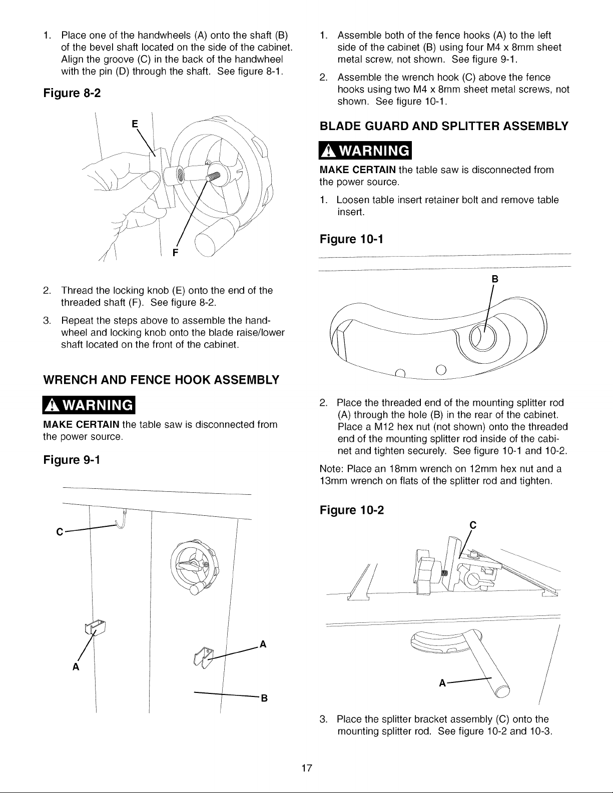
Place one of the handwheels (A) onto the shaft (B)
of the bevel shaft located on the side of the cabinet.
Align the groove (C) in the back of the handwheel
with the pin (D) through the shaft. See figure 8-1.
Figure 8-2
,
,
Assemble both of the fence hooks (A) to the left
side of the cabinet (B) using four M4 x 8mm sheet
metal screw, not shown. See figure 9-1.
Assemble the wrench hook (C) above the fence
hooks using two M4 x 8mm sheet metal screws, not
shown. See figure 10-1.
BLADE GUARD AND SPLITTER ASSEMBLY
MAKE CERTAIN the table saw is disconnected from
the power source.
1. Loosen table insert retainer bolt and remove table
insert.
Figure 10-1
,
,
Thread the locking knob (E) onto the end of the
threaded shaft (F). See figure 8-2.
Repeat the steps above to assemble the hand-
wheel and locking knob onto the blade raise/lower
shaft located on the front of the cabinet.
WRENCH AND FENCE HOOK ASSEMBLY
MAKE CERTAIN the table saw is disconnected from
the power source.
Figure 9-1
1
B
_Q ©
,
Place the threaded end of the mounting splitter rod
(A) through the hole (B) in the rear of the cabinet.
Place a M12 hex nut (not shown) onto the threaded
end of the mounting splitter rod inside of the cabi-
net and tighten securely. See figure 10-1 and 10-2.
Note: Place an 18mm wrench on 12mm hex nut and a
13mm wrench on flats of the splitter rod and tighten.
Figure 10-2
C
A
3. Place the splitter bracket assembly (C) onto the
mounting splitter rod. See figure 10-2 and 10-3.
17
Loading ...
Loading ...
Loading ...