Loading ...
Loading ...
Loading ...
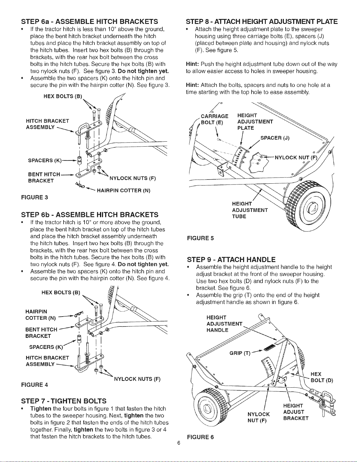
STEP 6a - ASSEMBLE HITCH BRACKETS
If the tractor hitch is less than 10" above the ground,
place the bent hitch bracket underneath the hitch
tubes and place the hitch bracket assembly on top of
the hitch tubes. Insert two hex bolts (B) through the
brackets, with the rear hex bolt between the cross
bolts in the hitch tubes. Secure the hex bolts (B) with
two nylock nuts (F). See figure 3. Do not tighten yet.
Assemble the two spacers (K) onto the hitch pin and
secure the pin with the hairpin cotter (N). See figure 3.
HEX BOLTS (B)
" C2 t OKET
SPACERS(K)--------__
BENT HITCH----_ _
BRACKET
FIGURE 3
/
NYLOCK NUTS (F)
%_"_ HAIRPIN COTTER (N)
STEP 6b - ASSEMBLE HITCH BRACKETS
If the tractor hitch is 10" or more above the ground,
place the bent hitch bracket on top of the hitch tubes
and place the hitch bracket assembly underneath
the hitch tubes. Insert two hex bolts (B) through the
brackets, with the rear hex bolt between the cross
bolts in the hitch tubes. Secure the hex bolts (B) with
two nylock nuts (F). See figure 4. Do not tighten yet.
• Assemble the two spacers (K) onto the hitch pin and
secure the pin with the hairpin cotter (N). See figure 4.
HEX BOLTS (B)
HAIRPIN
COTTER(N)
BENT HITCH
BRACKET )_
SPACERS(K
HITCH BRACKET
FIGURE 4
I
NYLOCK NUTS(F)
STEP 7 - TIGHTEN BOLTS
Tighten the four bolts in figure 1 that fasten the hitch
tubes to the sweeper housing. Next, tighten the two
bolts in figure 2 that fasten the ends of the hitch tubes
together. Finally, tighten the two bolts in figure 3 or 4
that fasten the hitch brackets to the hitch tubes.
STEP 8 - ATTACH HEIGHT ADJUSTMENT PLATE
Attach the height adjustment plate to the sweeper
housing using three carriage bolts (E), spacers (J)
(placed between plate and housing) and nylock nuts
(F). See figure 5.
Hint: Push the height adjustment tube down out of the way
to allow easier access to holes in sweeper housing.
Hint: Attach the bolts, spacers and nuts to one hole at a
time starting with the top hole to ease assembly.
CARRIAGE HEIGHT
BOLT (E)
SPACER (J)
NUT
HEIGHT
ADJUSTMENT
TUBE
FIGURE 5
STEP 9 - ATTACH HANDLE
Assemble the height adjustment handle to the height
adjust bracket at the front of the sweeper housing.
Use two hex bolts (D) and nylock nuts (F) to the
bracket. See figure 6.
• Assemble the grip (T) onto the end of the height
adjustment handle as shown in figure 6.
HEIGHT
ADJUSTMENT
HANDLE
HEX
FIGURE 6
HEmGHT
NYLOCK ADJUST
NUT (F) BRACKET
Loading ...
Loading ...
Loading ...