Loading ...
Loading ...
Loading ...
www.PyleUSA.com www.PyleUSA.com
9 10
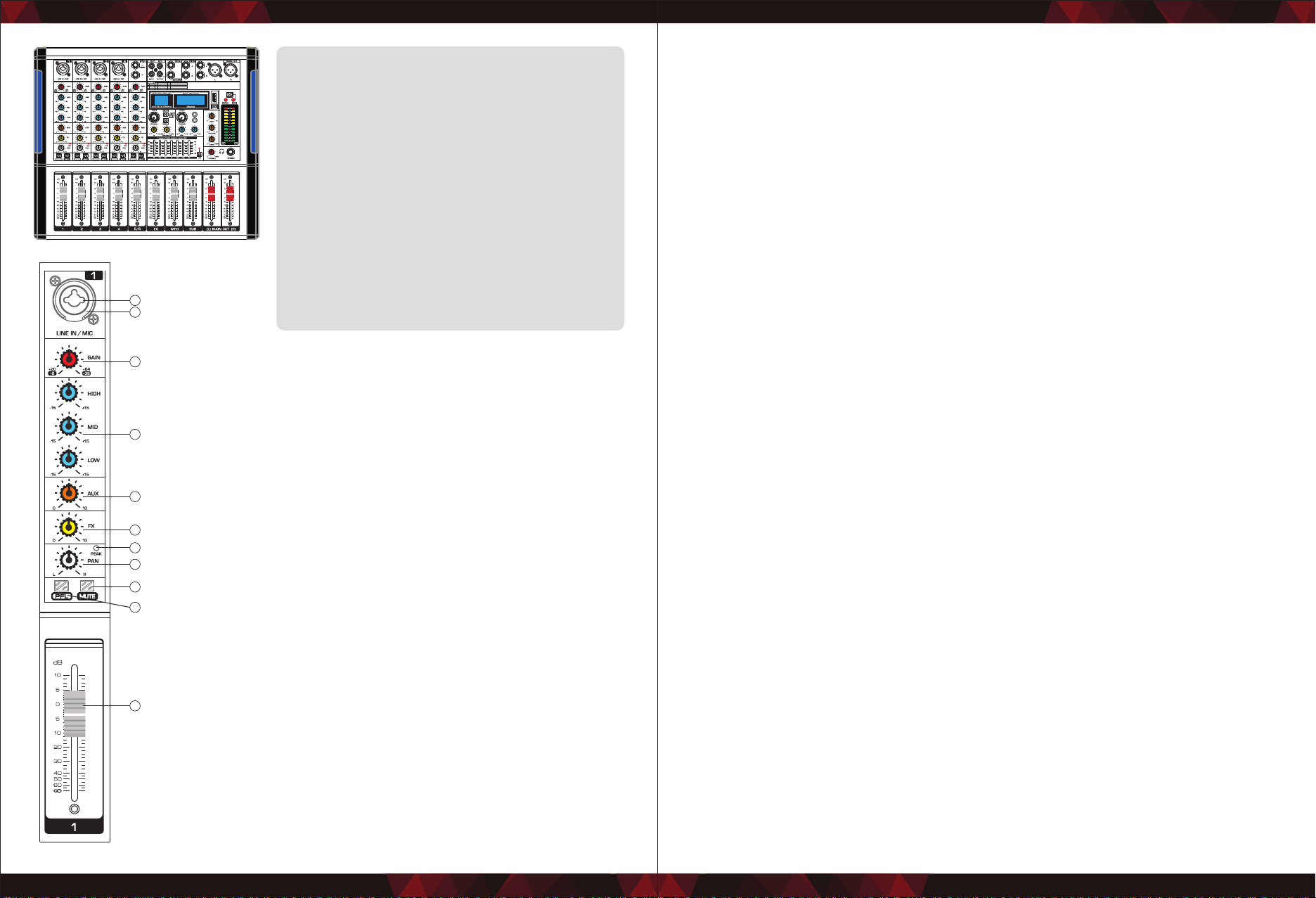
7. PEAK LED
The PEAK-LED lights up when the input signal is driven too high. If this happens,
back o the TRIM control and if necessary, check the setting of the EQ channel.
8 . PAN Control
The PAN control determines the position of the channel signal within the stereo
image. When working with sub groups, you can use the PAN control to assign the
signal to just one output, which gives you additional exibility in recording
situations.
9. M UTE Switch
The MUTE switch breaks the signal path pre-channel fader, hence muting that
channel in the main mix. The aux sends which are set to post-fader are likewise
muted for that channel, while the pre-fader monitor paths remain active
irrespective of whether the channel is muted or not.
10. PFL Switch
The PFL switch is used to route the channel signal to the the PFL bus (Pre Fader
Listen). This enables you to listento a channel signal without aecting the main
output signal. The signal you hear is taken either be fore the pan control (PFL
mono) .
11. CHANNEL FADER
Adjusts the level on the channel signal. Use these faders to adjust the balance
between the various channels.
12. TAPE INPUT/OUTPUT SOCKET
The TAPE IN jack (on stereo RCA) allows the connection of play-back devices such
as CD players etc. Use the TAPE OUT jack to connect, for example, a tape deck for
recording applications.
13. AUX/RETURN jacks
These are unbalanced phone-jack type line inputs. These jacks are typically used
to receive the signal returned from an external eect device (reverb, delay, etc.).
These pins can be connected, such as the eect of external equipment.
14. SUB Jack Bass Output Jack
15. Main IN/OUT (L,R) Jacks
These jacks delivers the mixer's stereo output. You use these jacks to connect the
power amplier to your main speakers.
16. EFFECTOR DISPLAY: Shows the kind of eector.
17. PROGRAM Control
You can select the eects preset by turning the PROGRAM control. The display
ashes with the number of the current preset. To recall the selected preset, press
ON the button; the ashing stops. You can also recall the selected preset with the
foot switch.
18. DSP MUTE SWITCH: Mutes the DSP or eects.
PHANTOM
01 HALL1
02 HALL2
03 ROOM1
04 ROOM2
05 REVERB+DELAY
06 125M S DELAY
07 175M S DELAY
08 225M S DELAY
10 560M S DELAY
09 285M S DELAY
11 860M S DELAY
12 1000M S DELAY
14 800M S PINGPON G DELAY
13 1400M S DELAY
15 1000M S PINGPON GDELAY
16 1400M S PINGPON G DELAY
FX
REC
REP/
MODE
PFL PFL PFL PFL PF L
1
3
4
5
6
7
8
9
11
10
2
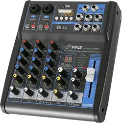
4/6/8/12/16 Input Channel Mixer,
New Multi-Voltage Power Supply
for Worldwide Use
4/6/8/12/16 Input Channel, Powered Mixer
• Built-in Bluetooth connects the mobile phone or
in other Bluetooth player
• Built-in MP3 player that supports variety of
music formats
• Connect the computer to record and play music
• Digital DSP, 16 Multi-FX effects
• Ultra -musical 3-band EQ on all channels
• Peak LED all Channels
• High accurate level indicator
• Phantom power switch (+48V )
• Sealed rotary controls to resist dust and grime
• Rugged steel chassis
1. MIC Input jacks
These are balanced XLR-type microphone input jacks.
(1: Ground; 2: Hot; 3: Cold)
2. LINE Input Jacks (monaural channels)
These are balanced TRS phone-jack line inputs.
(T: Hot; R: Cold; S: Ground). You can connect either balanced or
unbalanced phone plugs to these jacks.
3. GAIN Control
Adjusts the input signal level. To get the best balance between
the S/N ratio and the dynamic range, adjust the gain so that the
PEAK indicator only occasionally and briey on the highest input
transients. The -60 to +10 scale is the MIC input adjustment
range. The 40 to +10 scale is the LINE input adjustment range.
4. Equalizer 3 (HIGH, MID and LOW)
This three-band equalizer adjusts the channel's high, mid and
low frequency bands. Setting the knob to the "0" position
produces a at response in the corresponding band. Turning the
knob to the right boosts the corresponding frequency band,
while turning to the left attenuates the band.
5. AUX Control
Used to adjust the output to AUX pin signal level.
6. FX Control
Adjusts the level of the signal sent from the channel to the FX
SEND buses.
Loading ...
Loading ...
Loading ...