
till/F rSMnN°
MODEL NUMBER 917.258861 OWNER'SMANUAL
o Assembly
Operation
Customer Responsibilities
o Service and Adjustments
Repair Parts
....... CAUTION: Read and folloW all safety ruleS and instructions before op-_t_tting thiS equipment: "
FOR CONSUMER ASSISTANCE HOT LINE, CALL THIS TOLL FREE NUMBER: 1-800-659-5917
IIIllllllllllllllllllllI IIIII I
SAFETY RULES
_ Safe Operation Practices for Ride-On Mowers
IMPORTANT: THIS CUTTING MACHINE IS CAPABLE OF AMPUTATING HANDS AND FEET AND THROWING OBJECTS,
FAILURE TO OBSERVE THE FOLLOWING SAFETY INSTRUCTIONS COULD RESULT IN SERIOUS INJURY OR DEATH
...... DO
I
I. GENERAL OPERATION
• Road, understand, and follow all instructions in the manual
and on the machine before starting.
• Only allow responsible adults, who are familiar with the
instructions, to operate the machine.
• Clear the area of objects such as rocks, toys, wire, etc.,,
which could be picked up and thrown by the blade,
• Be sure the area is clear of other peopfe before mowing_ Stop
machine if anyone enters the area,
. Never carry passengers.
• Do not mow in reverse unless absolutely necessary, Always
look down and behind before and while backing
• Be aware el the mower discharge direction and do not point
it at anyone. Do not operate the mower without either the
entire grass catcher or the guard in place.
• Slow down before turning,,
• Never leave a running machine unattended, Always turn off
blades, set parking brake, stop engine, and remove keys
before dismounting,
• Turn off b[ades when not mowing
• Stop engine before removing grass catcher or unclogging
chute.
• Mow only in daylight or good artificial light.
. Do not operate the machine while under the influence of
alcohol or drugs.
• Watch for traffic when operating near or crossing roadways.
• Use extra care when loading or unloading the machine into
a trailer or truck.
IL SLOPE OPERATION
Slopes are a major factor related to Ioss-of-centre_ and tipover
accidents, which can result in severe injury or death. All slopes
require extra caution ffyou cannot back up the slope or if you fee{
uneasy on it, do not mow it
DO:
. Mow up and down slopes, nat across
• Remove obstacles such as rocks, tree limbs, etc.
• Watch for holes, ruts, or bumps_ Uneven terrain could
overturn the machine, Tall grass can hide obstacles_
• Use slow speed Choose a low gear so that you will not have
to stop or shift while on the slope.
• Follow the manufacturer's recommendations for wheel
weights or counterweights to improve stability,
• Use extra care with grass catchers or other attachments.
These can change the stability of the machine.
• Keep nit movement on the slopes slow and gradual. Do not
make sudden changes in speed or direction.
• Avoid starting or stopping on a slope. 11tires lose traction,
disengage the blades and proceed slowiy straight down the
slope_
NOT: "- - .......
Donet turn on slopes unless necessary, and then, turn stowly
and gradua{fy downhill, if possible.
• Do not mew near drop-ells, ditches, or embankments. The
mower could sudden(y turn over if a wheel is over the edge
of a cliff or ditch, or if an edge caves in_
• Do not mow on wet grass, Reduced traction could cause
sliding,
• Do not try to stabilize the machine by putting your foot on the
ground,
• Do not use grass catcher on steep slopes.
2
IlL CHILDREN
Tragic acc(dents can occur if the operator is not alert to the
presence of children. Children are often attracted to the machine
and the mowing activity Never assume that children will remain
where you last saw them
• Keep children out of the mowing area and under the watchful
care of another responsible adult.
• Be alert and turn machine off if children enter the area.
• Before and when backing, Iook behind and/_own for small
children.
• Never carry children, They may fall off and be seriously
injured or interfere with safe machine operation.
• Never allow chtfdren to operate the machine.
• Use extra care when approaching blind corners, shrubs,
trees, or other objects that may obscure vision
IV. SERVICE
* Useexlracareinhandlinggasolineandotherfuels. Theyare
ftammab[e and vapors are explosive
Use oniy an approved container
Never remove gas cap or add fuel with the engine
running., Ai[ow engine to cool before refueling Do not
smoke.
Never refuel the machine indoors.
Never store the machine or fuel container inside where
there is an open flame, such as a water heater
. Never run a machine inside a closed area,
. Keep nuts and bolts, especially blade attachment bolts, tight
and keep equipment in good condition,
- Never tamper with safety devices., Check their proper
operation regularly,
- Keep machine free of grass, leaves, or other debris build-up.
Clean oil or fuel spillage, Allow machine to cool before
storing.
• Stop and inspect the equipment if you strike an object.
Repair, if necessary, before restarting.
• Never make adjustments or repairs with the engine running,
. Grass catcher components are subject to wear, damage, and
deterioration, which could expose moving parts or allow
objects to be thrown. Frequently check components and
replace with manufacturer's recommended parts, when nec-
essary_
• Mower blades are sharp and can cut Wrap the blade(s) or
wear gloves, and use extra caution when servicing them,,
- Check brake operation frequently Adjust and service as
required.
iii iiii iiiii iiii iii fil iiiiiiiiiiiii i i iii
Look for this symbol to point out important !
safety precautions. It means
I
CAUT1ONItf BECOME ALERT.qI YOUR
SAFETY IS INVOLVED.
illU ij
I- .... I
CAUTION: Always disconnect spark plug
wire and place wire where it cannot contact
spark plug in order to prevent accidental
starting when setting up, transporting,
adjusting or making repairs. .......
A WARNING A
The engine exhaust from this product con-
tains chemicals known to the State of Califor-
nia to cause cancer, birth defects, or other
. reprod,uct!ve,, harm: ,,,

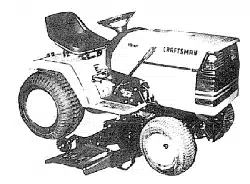
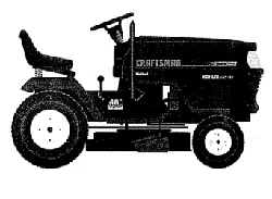
CONGRATULATIONS on your purchase of a Sears
Tractor. It has been designed, engineered and manufac-
tured to give you the best possible dependability and
performance.
Should you experience any problem you cannot easily
remedy, p_ease contact your nearest Sears Authorized
Service Center/Department We have competent, wolf
trained technicians and the proper' tools to service or repair
this tractor.
Please read and retain this manual. The instructions will
enable you to assemble and maintain your tractor properly_
Always observe the "SAFETY RULES".
MODEL
NUMBER 917.258861
SERIAL
NUMBER
DATEOF PURCHASE
THE MODELAND SERIAL NUMBERSWILL BE FOUND
ON A PLATE UNDER THE SEAT.
YOU SHOULD RECORD BOTH SERIAL NUMBER AND
DATE OF PURCHASE AND KEEP IN A SAFE PLACE
FOR FUTURE REFERENCE.
MAINTENANCE AGREEMENT
A Sears Maintenance Agreement is available on this prod-
ucL Contact your nearest Sears store for details.
CUSTOMER RESPONSiBBLITIES
- Read and observe the safety rules°
- Follow a regular schedule in maintaining, caring for and
using your tractor,
• Follow the instructions under' "Customer Responsibili-
ties" and "Storage" sections of this owner's manual..
WARNING: This tractor is equipped with an internal
combustion engine and should not be used on or near any
unimproved forest-covered, brush-covered or' grass-cov-
ered !and un!ess the engine's exhaust sys!,emiSequipped
PRODUCT SPECIFICATIONS
HORSEPOWER: 1&5
GASOLINE CAPACITY
AND TYPE:
OIL TYPE (APFSF!SG/SH):
3.5 GALLONS
UI_LEADED REGULAR
SAE 30 (alCove 32°F)
SAE 5W-30 (below 32°F)
OIL CAPACITY: W/FILTER: 4.0 PINTS
W/O FILTER: 3.5 PINTS
SPARK PLUG: CHAMPION RV17YO
(GAP: _025")
VALVE CLEARANCE: INTAKE: .,003" - °006"
EXHAUST: 0t3"- 016"
GROUND SPEED (MPH): Forward LO HI
1st 0.7 1.7
2nd 14 33
3rd 2.3 &4
Reverse 0.9 241
TRANSAXLE OIL 4 QUARTS
CAPACITY AND TYPE: SAE 30 API-SF/SG
TIRE PRESSURE: FRONT: 14 PSI
REAR: 10 PSI
CHARGING SYSTEM: 15 AMPS @ 3600 RPM
BATTERY: AMP/HR: 30
MIN° CCA: 240
CASE SIZE: U1R
BLADE BOLT TORQUE: 30-35 FT. LBS.
with a spark arrester meeting applicable local or state laws
(if any), If a spark arrester is used, it should be maintained
in effective working order by the operator,
In the state of California the above is required by law
(Section 4442 of the California Public Resources Code)°
Other states may have similar laws. Federal laws apply on
federal lands. A spark arrester for the muffler is available
through your nearest Sears Authorized Service Cented
Department (See REPAIR PARTS section of this manual).
ii iii ii1,1111111111 i iii iii i i
LIMITED TWO YEAR WARRANTY ON CRAFTSMAN RIDING EQUIPMENT
For two (2) years from the date of purchase, if this Craftsman Riding Equipment is maintained, tubdcated and tuned up according
to the instructions in the owner's manual, Sears will repair or replace, free of charge, any parts found to be defective in materiat
or workmanship.
This Warranty does not cover:
• Expendable items which become worn during normal use, such as blades, spark plugs, air cleaners° belts, etc.
• Tire replacement or repair caused by punctures from outside objects, such as nails, thorns, stumps, or' grass.
• Repairs necessary because of operator abuse, negligence, improper storage or' accident or the failure to maintain the
equipment according to the instructions contained in the owner's manual
° Riding equipment used for commercial or rental purposes..
LIMITED 90 DAY WARRANTY ON BATTERY
" For ninety (90) days from date of purchase, if any battery included with this riding equipmentproves defective in material or
workmanship and our testing determines the battery wilt not held a charge, Sears will replace the battery at no charge..
IN-HOME WARRANTY SERVICE ON YOUR CRAFTSMAN RIDING EQUIPMENT IS AVAILABLE AT NO-CHARGE FOR 30
DAYS FROM THE DATE OF PURCHASE. PLEASE CONTACT YOUR NEAREST SERVICE CENTER. AFTER 30 DAYS
FROM THE DATE OF PURCHASE, WARRANTY SERVICE IS AVAILABLE BY TAKING YOUR CRAFTSMAN RIDING EQUIP-
MENT TO YOUR NEAREST SEARS SERVICE CENTER. 0N-HOME WARRANTY SERVICE WILL STILL BE AVAILABLE
AFTER 30 DAYS FROM THE DATE OF PURCHASE BUT A STANDARD TRIP CHARGE WILL APPLY.) THiS WARRANTY
APPLIES ONLY WHILE THIS PRODUCT IS IN THE UNITED STATES .......
This Warranty gives you specific legal dghts, and you may also have other rights which may vary from state to state
SEARS, RQEBUCK AND CO., D/817 WA, HOFFMAN ESTATES, IL 60179
................ tllllllI i,ii ,i i,,11,, ,,,i , iiiiiiiiiiiiI i,i
3
TABLE OF CONTENTS
SAFETY RULES ................ ;........................................... 2
PRODUCT SPECIFICATIONS ...................................... 3
CUSTOMER RESPONSIBILITIES ..................... 3, 17-20
WARRANTY .................................................................. 3
TRACTOR ACCESSORIES .......................................... 5
ASSEI_BLY .............................................................. 7-10
OPERATION ........................................................... 11-16
MAINTENANCE SCHEDULE ...................................... 17
SERVICE AND ADJUSTMENTS ............................ 21-27
STORAGE ................................................................... 28
TROUBLESHOOTING ............................................ 29-30
REPAIR PARTS - TRACTOR ................................. 32-49
REPAIR PARTS - ENGINE .................................... 50-59
PARTS ORDERING/SERVICE ................ BACK COVER
iNDEX
A
Accessories ............................................. 5
Adjustments:
Brake ....................................................23
Carburetor ..............................................27
Clutch Pulley ..........................................23
Gauge Wheels ..........................................14
Mower
Front-To-Back ............................ 22
Side-To-Side ................................21
Throttle Control Cable ...........................27
Air Filter, Engine ...........................................20
Air Screen, Engine ................................ 20
Assembly .....................................................7-10
B
Battery:
Charging ........................................ 8
Cleaning .................................................19
Starting with Weak Battery ............25
Storage ...............................................28
Terminals ............................................t9
Belt:
Motion Drive
Removal/Replacement .............24
Mower Drive
Removal/Replacement ........... 22
Mower Blade Drive
Removal/Replacement .............23
Blade:
Sharpening ..................................... 18
Replacement .................................................18
Brake Adjustment ................................. 23
C
Carburetor Adjustment ..............................27
Clutch Pulley ....................................... 23
Controls, Tractor ........................................ 12
Custome_ Responsibilities ..................t 7-20
Engine:
Air Filter ..........................................20
Air Screen ..................................................20
Cooling Fins .......................................20
Engine Oil ......................................14,19
Fuel Filter-;;; r"........;.......;................. 20"
Spark Plug(s) .............................. 20
Tractor:
Battery ..............................................19
Blade .................................................18
Lubrication Chart ....................... t7
Maintenance Schedule ..............t7
Tire Care ..................................10,18,25
Transaxle .......................................... 18
Cutting Height, Mower .......................... 13
E
Electrical:
Interlocks and Relays .....................25
Schematic ........................................ 31
Wiring Diagram .................................. 32
Engine:
Air Filter ........................................ 20
Air Screen ................................ 20
Cooling Fins .................................. 20
Oil Change .................................. 19
Oil Level ..................................... 19
Oil Type ...................................... 14,19
Preparation ................................. 14
Repair Parts ............................ 50-59
Starling .................................. t4,16
Storage .................................. 28
F
Filter:
Air Filter ......................... 20
Fuel ............................................... 20
Oil ........................................................20
Fuel:
Storage ............................... 28
Type ........................................... 15
Fuse ............................................... 25
H
Headlights ................................... 25
Hood Removal/Installation ................ 26
L
Leveling Mower Deck .......................... 21
Lubrication:
Chart .................................................. 17
Engine ............................................. 19
M
Maintenance Schedule ............................17
Mower:
Adjustment, Front-to-Back .......... 22
Adjustment, Side-to-Side ............... 21
Blade Replacement ...................... 18
Blade Sharpening ...............................18
- • Cutting Height ...;., ..,,:..:,... ;:.:.: 13
Installation ...................................... 21
Operation .......................................... 14
Removal ........................................ 21
Mowing Tips ................................................15
Muffler ...................................................... 19
Spark Attester ............................ 3,40
Oil:
O
Cold Weather Conditions ........ 15,19
Engine ..................................... 19
Storage ......................................... 28
Operation ........................................... 11-16
Operating Mower. .....................................14
Options:
Accessories ...................................... 5
Spark Arrester ...............................3,40
P
Parking Brake ................................. 12-t3
Parts Bag ................................................... 6
Parts, Replacement/Repair ...............32-49
Product Specifications .....................................3
R
Repair Parts ........................................32-47
S
Safety Rules ...........................................................2
Seat ......................................................................8
Service and Adjustments ................. 21-27
Carburetor ............................................27
Clutch Pulley .....................................23
Fuse ......................................................... 25
Hood Removal/Installation ...............26
Motion Drive Belt
Removal/Replacement ............ 24
Mower Drive Belt
Removal/Replacement ............ 22
Mower Blade Drive Belt
Removal!Replacement ...............23
Mower Adjustment
Front-to-Back .............................. 22
Side-to-Side ..................................21
Mower Removalflnstallation ......... 21
Tire Care .....................................10,18,25
Slope Guide Sheet ....................................63
Spark Plug(s) ...............................................20
Specifications ............................................. 3
Starting the Engine ..................................14-16
Steering Wheel ...........................................7,24
Stopping the Tractor ...................................13
Storage .................................................... 28
....... T ..........
Throttle Conlrol Cable Adjustment .........27
Tires ....................................................10,18,25
Troubleshooting Chart ........................29-30
Transaxle .........................................18,48-49
W
Warranty ..........................................................3
Wiring Diagram ................................... 32
Wiring Schematic .......................................... 31
ATTACH M NTS
ii i ii ,llllll i i ,,111.....................................................
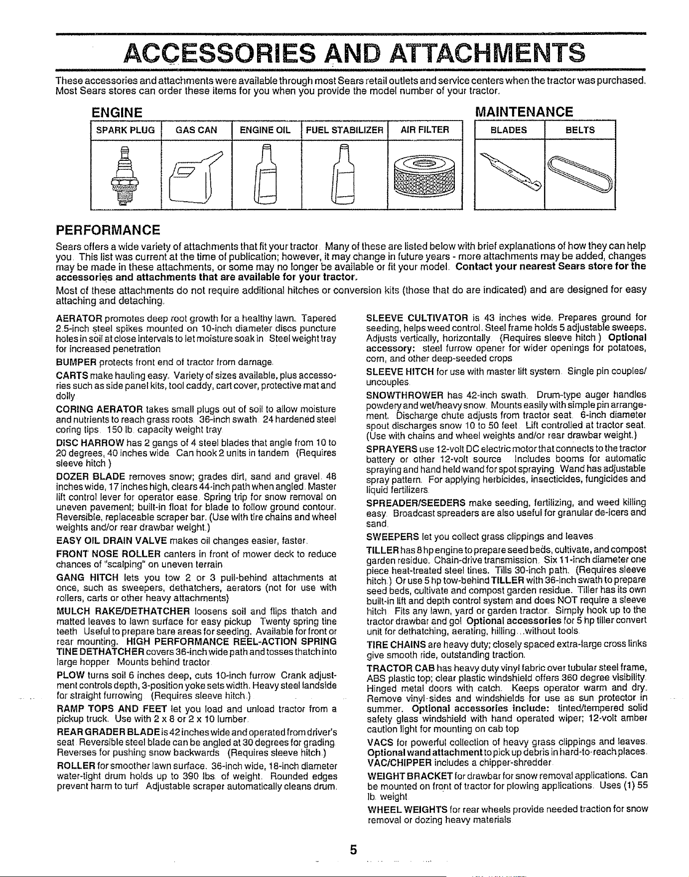
These accessories and attachments were availabIe through most Sears retail outlets and service centers when the tractorwas purchased.
Most Sears sto_es can order these items for you when you provide the model number of your tractor.
ENGINE
SPARK PLUG
MAINTENANCE
GAS CAN BLADESENGINE OIL
2
FUEL STABILIZER AiR FILTER
6
BELTS
PERFORMANCE
Sears offers a wide variety of attachments that fit your tractor Many of these are listed below with brief explanations of how they can help
you This list was current at the time of pubjlcation; however, it may change in future years - more attachments may be added, changes
may be made in these attachments, or some may no longer be available or fit your model. Contact your nearest Sears store for the
accessories and attachments that are available for your tractor'.
Most of these attachments do not require additional hitches or conversion kits (those that do are indicated) and are designed for easy
attaching and detaching
AERATOR promotes deep root growth for a healthy lawn., Tapered
25-inch steel spikes mounted on lO-inch diameter discs puncture
holes in soil at close intervals to let moisture soak in Steelweight tray
for increased penetration
BUMPER protec{s front end of tractor from damage
CARTS make hauling easy. Variety of sizes available, plus accesso-
ries such as side panel kits, tool caddy, cart cover, protective mat and
doily
CORING AERATOR takes small plugs out of soil to allow moisture
and nutrients to reach grass roots 36-inchswath 24hardenedsteeL
coring tips 150 Ib capacity weight tray
DISC HARROW has 2 gangs of 4 steel blades that angIe from 10 to
20 degrees, 40 inches wide Can hook 2 units in tandem (Requires
sleeve hitch )
DOZER BLADE removes snow; grades dirt, sand and gravel 48
inches wide, 17 inches high, clears 44-inch path when angled, Master
lift control lever for operator ease. Spring tdp for snow removal on
uneven pavement; built-in float for' blade to follow ground contour,
Reversible, replaceabJe scraper bar.r (Use with tire chains and wheel
weights and/or rear drawbar weight.)
EASY OIL DRAIN VALVE makes oil changes easier, faster.
FRONT NOSE ROLLER canters in front of mower deck to reduce
chances of "scalping" on uneven terrain
GANG HITCH lets you tow 2 or 3 pull-behind attachments at
once, such as sweepers, dethatchers, aerators (not for use with
rollers, carts or' other' heavy attachments)
MULCH RAKFJDETHATCHER loosens soil and _ps thatch and
malted leaves to iawn surface for easy pickup Twenty spring line
teeth Useful to prepare bare areas for seeding, Available for front or
rear mounting. HIGH PERFORMANCE REEL-ACTION SPRING
TiNE DETHATCHER covers 36-inch wide path and tosses thatch into
large hopper Mounts behind tractor
PLOW turns soil 6 inches deep, cuts t0-inch furrow Crank adjust-
ment controls depth, 3-positlon yoke sets width, Heavy steel tandside
for straight furrowing (Requires sleeve hiich )
RAMP TOPS AND FEET let you load and unload tractor from a
pickup truck. Use with 2 x 8 or 2 x 10 lumber,
REAR GRADE R BLADE is 42 inches wide and operated from ddver's
seat Reversible steel blade can be angled at 30 degrees for grading
Reverses for pushing snow backwards (Requires sleeve hitch.)
ROLLER for smoother lawn surface, 36-inch wide, 18-inch diameter
water-tight drum holds up to 390 Ibs of weight. Rounded edges
prevent harm to turf Adjustable scraper automatically cleans drum.
SLEEVE CULTIVATOR is 43 inches wide, Prepares ground for
seeding, helps weed control. Steel frame holds 5 adjustable sweeps.
Adjusts vertically, horizontally (Requires sleeve hitch ) Optional
accessory: steel furrow opener for wider openings for potatoes,
corn, and other deep-seeded crops
SLEEVE HITCH for use with master lift system Single pin couples!
uncouples
SNOWTHROWER has 42-inch swath Drum-type auger handles
powdery and web'heavy snow Mounts easily with simple pin arrange-
merit, Discharge chute adjusts from tractor seat, 6-inch diameter
spout discharges snow 10 to 50 feet Lift controlled at tractor seat,
(Use with chains and wheel weights and/or rear drawbar weight,)
SPRAYERS use 12-vott DC electric motor that connecis to the tractor
battery or other 12-volt source Includes booms for automatic
spraying and hand heldwandforspotspraying Wand has adiustable
spray pattern, For applying herbicides, insecticides, fungicides and
liquid fertilizers
SPREADER/SEEDERS make seeding, fertilizing, and weed killing
easy Broadcast spreaders are also useful for granular de-[cers and
sand
SWEEPERS let you collect grass clippings and leaves
TILLER has 8 hp engine to prepare seed beds, cultivate, and compost
garden residue. Chain-drive transmission. Six 11-inch diameter one
piece heaHreated steel tines. Tilts 30-inch path. (Requires sleeve
hitch.) Or use 5 hp tow-behind TILLER with 36-inch swath to prepare
seed beds, cultivate and compost garden residue. Tiller has its own
built*in lift and depth control system and does NOT require a sleeve
hitch Fits any iawn, yard or garden tractor. Simply hook up to the
tractor d_awbar and go! Optional accessories re{5 hp tiller convert
unit for dethatching, aerating, hilling.owithout tools
TIRE CHAINS are heavy duty; closely spaced extra-large cross links
give smooth ride, outstanding traction.
TRACTOR CAB has heavy duty vinyl fabric over tubular steel frame,
ASS plastictop; ctear plastic windshield offers 360 degree visibility
Hinged metai doors with catch_ Keeps operator warm and dry.
Remove vinyFsides and windshields .for use as sun protector in
summer'. Optional accessories include: tJntedltempered solid
safety glass windshield with hand operated wiper; 12-volt amber
caution light for mounting on cab top
VACS for powerful collection of heavy grass clippings and leaves.
Optional wand attach merit to pick up debris in ha rd-to-reach places.
VACtCHIPPER inctudes a chipper-shredder
WEIGHT B RACKET for drawbar for snow remove1applications. Can
be mounted on {ro.nt of tractor for plowing applications Uses (1) 55
Ib weight
WHEEL WEIGHTS for rear wheels provide needed traction for snow
removal or dozing heavy materials
5
•- i ,u lU ,i ....i,iiiii u, ,, ii i,,u ..... i1,,,,11
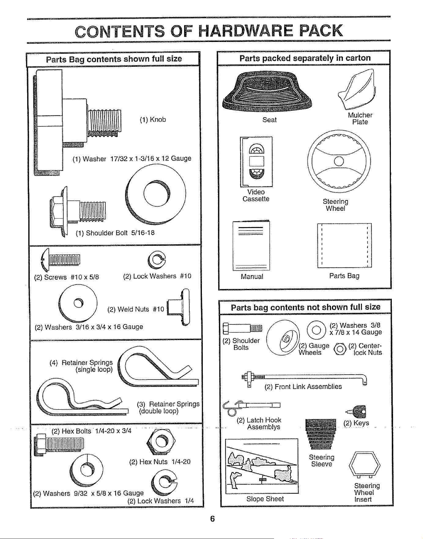
CONTENTS OF HARDWARE PACK
........ u ,, m-lmr i,, ll...mHi, i u
,ul ' ,u, lllllllll I' ill i,i
Parts Bag contents shown full size Parts packed separately in carton
_Lu_ i,, ,,m,i u i H 'M,',,'I ..... II
(1) Knob
(1) Washer 17/32 x 1-3/16 x 12 Gauge
(1) Shoulder Bolt 5/16-18
(2) Screws #10 x 5/8
ii1,111 i
@
(2) Lock Washers #10
/-h
(2) Weld Nuts #10 _':-I I
(2) Washers 3/16 x 3/4 x t6 Gauge
(4) Retainer Springs
(single loop)
(3) Retainer Springs
(double loop)
ltS 1/4-20 x 3/4 "_ .......
(2) Hex Nuts 1/4-20
(2) Washers 9/32 x 5/8 x 16 Gauge
(2) Lock Washers 1/4
, i,,i, mu.,,,i .....
Mulcher
Seat Plate
J , ,, ,,,,
"Video
Cassette
Steering
Wheel
Manuat
.....Ii....
Parts Bag
,1_ i, UUlllU
Parts bag contents not shown full size
• =.....................
//"--'_ _ (2)Washers 3/8
(/_) _xZ/8x14Gauge
(2) Shoulder'Bolts_. _//'/!2) Gauge Z_ (2) Center-
WheeIs _ lock Nuts
_8_1_ .........
(2) Front Link Assemblies
(2) Latch Hook
-- Assemblys
Steering
Sleeve
Slope Sheet
(2) Keys ........
Steering
Wheel
Insert
, u,,,,,
ASSEMBLY
Your new tractor has been assembled at the factory with the exception of those parts left unassembled for shipping purposes°
To ensure safe and proper operation of your tractor all parts and hardware you assemble must be tightened securely. Use
the correct tools as necessary to insure proper' tightness.
TOOLS REQUIRED FOR ASSEMBLY
A socket wrench set will make assembly easier_. Standard
wrench sizes are listed_
(2) 7/16" wrenches
(1) 1/2" wrench
(1) 9/16" wrench
Phillips screwdriver
Tire pressure gauge
Utility knife
Pliers
(1) 3/4" socket with drive ratchet
When right or left hand is mentioned in this manual, it
means when you are in the operating position (seated
behind the steering wheel)
TO REMOVE TRACTOR FROM CARTON
UNPACK CARTON
• Remove air accessible loose parts and parts cartons
from carton (See page 6).
• Cut, from top to bottom, along lines on all four corners
of carton, and lay panels flat.
• Remove mower and packing materials.
° Check for any additional loose parts or cartons and
rernove.
BEFORE ROLLINGTRACTOR OFF SKID
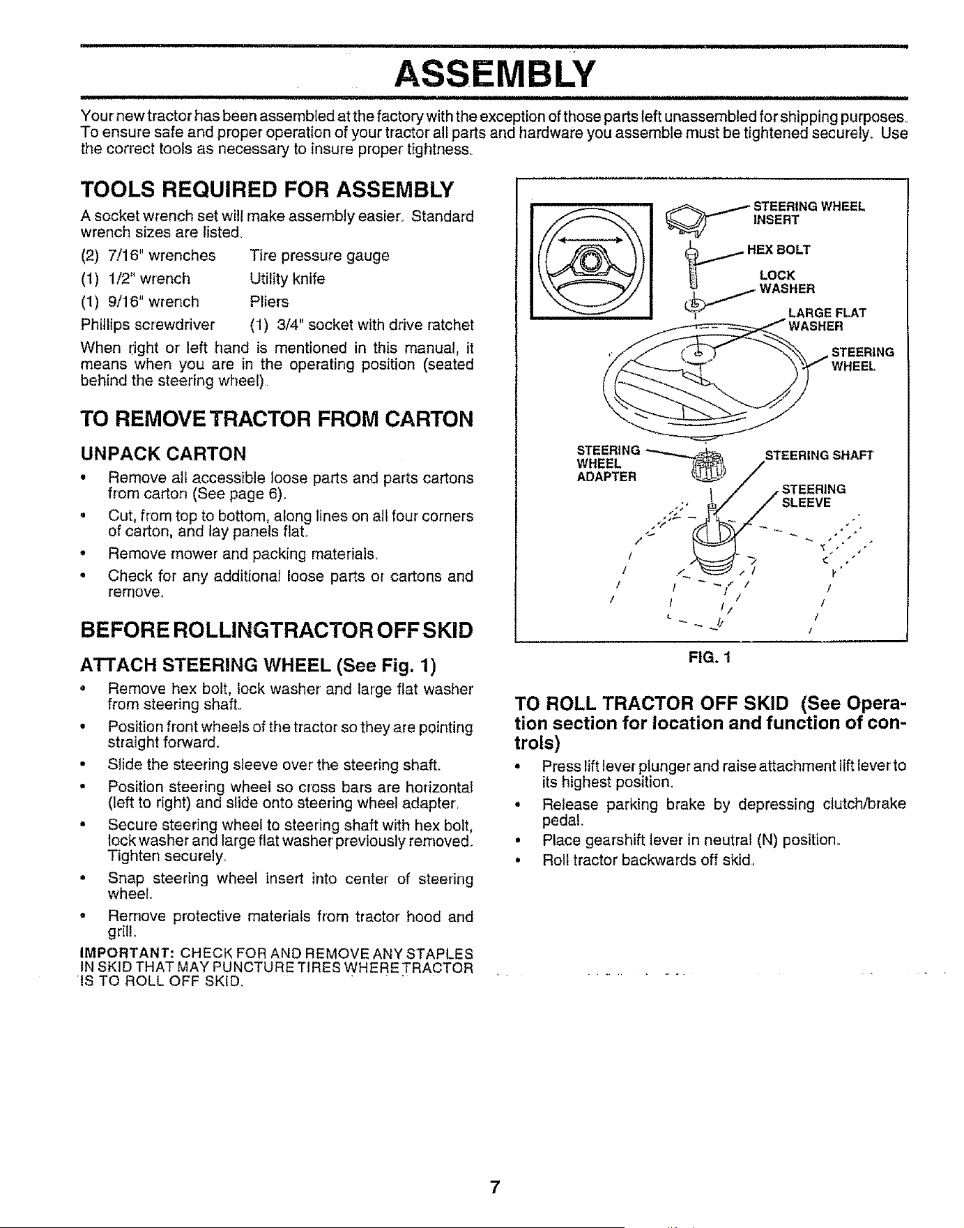
ATTACH STEERING WHEEL (See Fig. 1)
o Remove hex bolt, lock washer and large flat washer
from steering shaft..
• Position front wheels of the tractor so they are pointing
straight forward.
• Slide the steering sleeve over' the steering shaft.
• Position steering wheel so cross bars are horizontal
(left to fight) and slide onto steering wheel adapter,
• Secure steering wheel to steering shaft with hex bolt,
tock washer and large flat washer previously removed..
Tighten securely.
• Snap steering wheel insert into center of steering
wheel.
° Remove protective materials from tractor' hood and
grill
IMPORTANT: CHECK FOR AND REMOVE ANY STAPLES
IN SKID THAT MAY PUNCTURE TIRES WHER E TRACTOR
IS TO ROLL OFF SKID_
_ TEERING WHEEL
INSERT
HEX BOLT
LOCK
_1_,_ WASHER
LARGE FLAT
STEERING _ _
WHEEL _
ADAPTER _'__._._
1I/'_ /"
1 ! _ l"
/ / 1
STEERING SHAFT
/
STEERING
SLAVE
/
/
/
f
FIG. 1
TO ROLL TRACTOR OFF SKID (See Opera-
tion section for location and function of con-
trols)
• Press lift lever plunger and raise attachment lift lever'to
its highest position.
• Release parking brake by depressing clutch/brake
pedal°
• Place gearshift lever in neutral (N) position..
• Roll tractor backwards off skid.
=,q., = = ,,= ,=
ASS
HOW' TO SET UP YOUR TRACTOR
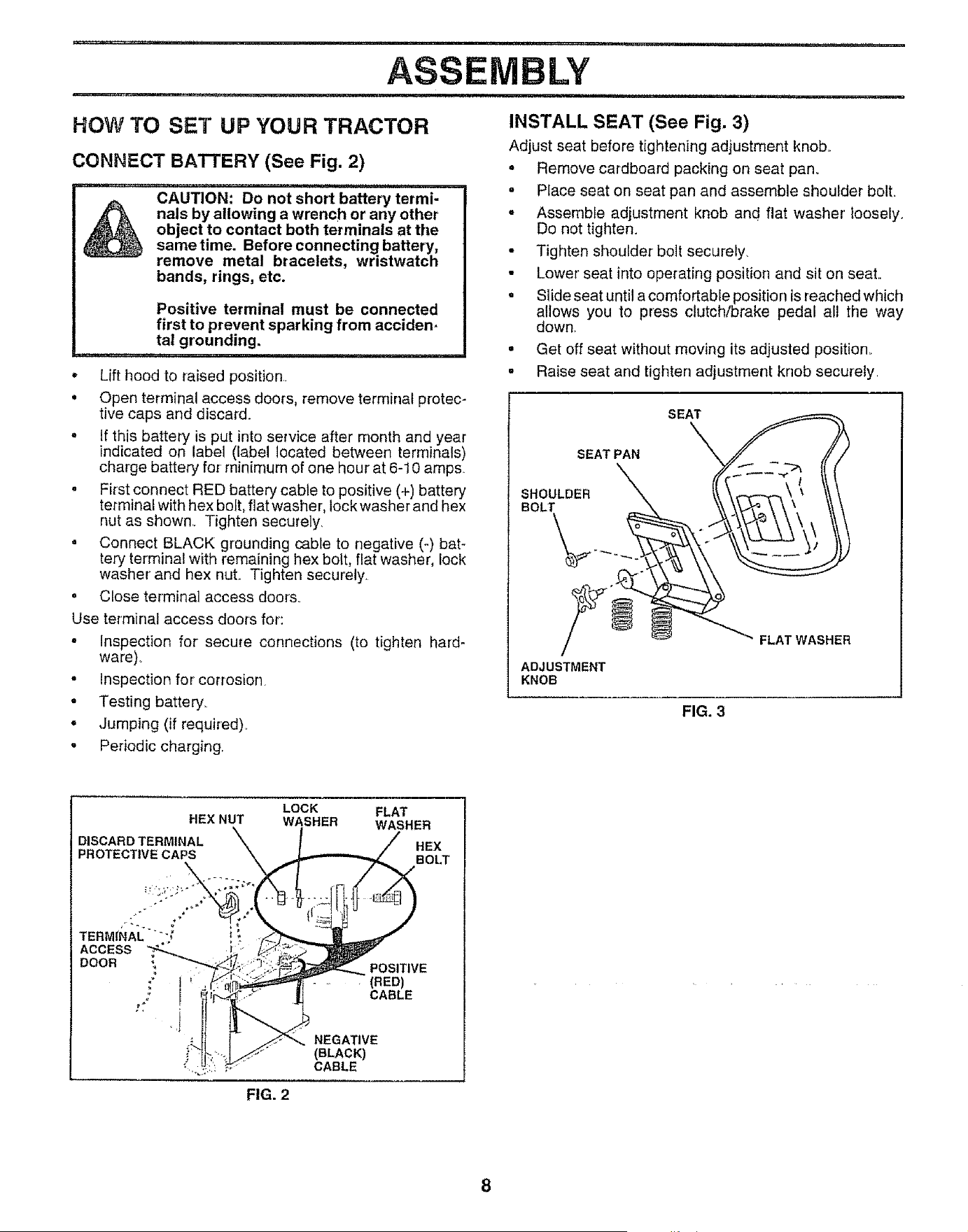
CONNECT BATTERY (See Fig. 2)
=m===a_ ..........................................................
_, CAUTION: Do not short battery termi-
nals by allowing a wrench or any other
object to contact both terminals at the
same time. Before connecting battery,
remove metal bracelets, wristwatch
bands, rings, etc.
Positive terminal must be connected
first to prevent sparking from acciden-
tal grounding.
.... M,I,I,,I,II,,I,,I,,, ,i,,
* Lift hood to raised position,
. Open terminal access doors, remove terminal protec-
tive caps and discard.
. If this battery is put into service after month and year
indicated on label (label located between terminals)
charge battery for minimum of one hour at 6-10 amps
. First connect RED battery cable to positive (+) battery
terminal with hex bolt, flat washe r, lock washer and hex
nut as shown,, Tighten securely.
= Connect BLACK grounding cable to negative (-) bat-
tery terminal with remaining hex bolt, flat washer, lock
washer and hex nut.. Tighten securely,
o Close terminal access doors.
Use terminal access doors for:
. Inspection for secure connections (to tighten hard-
ware).
, Inspection for corrosion
, Testing battery_
. Jumping (if required)_
° Periodic charging.
mu,=...... m-=, i n u ,= i ........
LY
i,, , mmii-,n= n,
INSTALL SEAT (See Fig. 3)
Adjust seat before tightening adjustment knob,,
• Remove cardboard packing on seat pan.
- Place seat on seat pan and assemble shoulder bolt.
- Assemble adjustment knob and flat washer' looseiy.
Do not tighten•
• Tighten shoulder bolt securely.
• Lower' seat into operating position and sit on seat.
• Slide seat untila comfortable position isreached which
allows you to press clutch/brake pedal all the way
down.
• Get off seat without moving its adjusted position.
. Raise seat and tighten adjustment knob securely,
SEAT
SEAT PAN
.00 LOER \\\
/__ FLAT WASHER
ADJUSTMENT
KNOB
FIG. 3
LOCK FLAT
HEX NUT WASHER WASHER
DISCARD TERMINAL HEX
PROTECTIVE CAPS BOLT
TERMINAL ",
ACCESS
DOOR
POSITIVE
(RED)
CABLE
NEGATIVE
(BLACK)
CABLE
FIG. 2
N==, INHI I HI= Hm, I1=
ASSEMBLY
LJlIJ I III I I
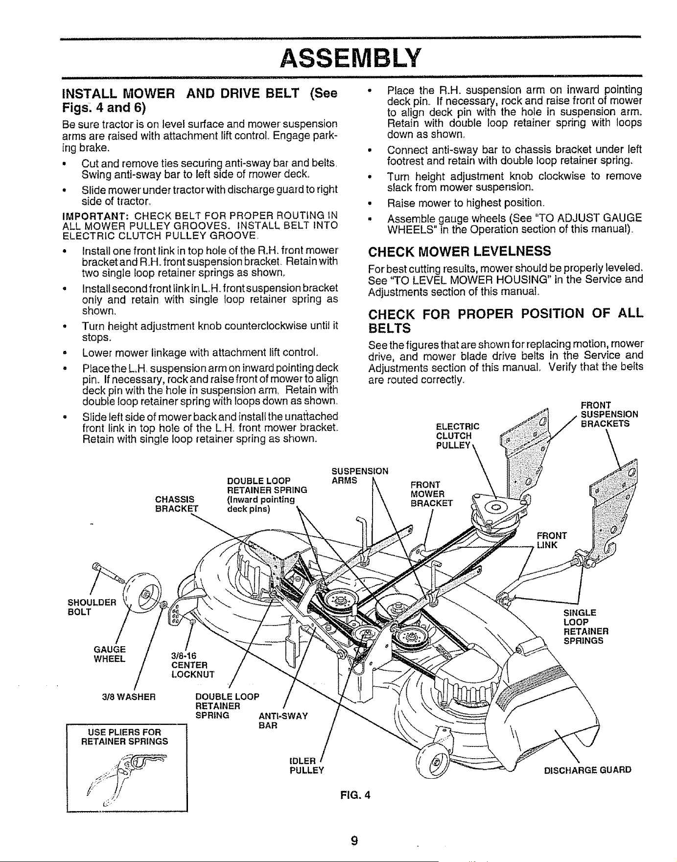
INSTALL MOWER AND DRIVE BELT (See °
Figs. 4 and 6)
Be sure tractor is on level surface and mower' suspension
arms are raised with attachment lift control Engage park-
ing brake.
• Cut and remove ties securing anti-sway bar and belts,
Swing anti-sway bar to left side of mower decks .
• Slide mower' under tractorwith discharge guard to right
side of tractor°
IMPORTANT; CHECK BELT FOR PROPER ROUTING IN .
ALL MOWER PULLEY GROOVES. INSTALL BELT INTO
ELECTRIC CLUTCH PULLEY GROOVE.
• Install one front link intop hole of the R.H. front mower'
bracket and R.H. front suspension bracket, Retain with
two single loop retainer springs as shown,,
° Install second front link in L,H. front suspension bracket
only and retain with single loop retainer' spring as
shown.
° Turn height adjustment knob counterclockwise until it
stops.
= Lower mower linkage with attachment liftcontrol
o Place the L.H suspension arm on inwardpointing deck
pin. Ifnecessary, rock and raise front of mower to align
deck pin with the hole in suspension army Retain with
double loop retainer spring with loops down as shown,,
° Slide left side of mower back and instali the unattached
front link in top hole of the LH front mower bracket. ELECTRIC
Retain with single loop retainer spring as shown. CLUTCH
=H H,m ' =
Place the R.H. suspension arm on inward pointing
deck pin., If necessary, rock and raise front of mower
to align deck pin with the hole in suspension arm.
Retain with double loop retainer' spring with loops
down as shown_
Connect anti-sway bar to chassis bracket under left
footrest and retain with double loop retainer spring.
Turn height adjustment knob clockwise to remove
slack from mower suspension.
Raise mower' to highest position.
Assemble gauge wheels (See "TO ADJUST GAUGE
WHEELS" in the Operation section of this manual).
CHECK MOWER LEVELNESS
For' best cutting resutts, mower should be properly leveled.
See "TO LEVEL MOWER HOUSING" in the Service and
Adjustments section of this manual,
CHECK FOR PROPER POSITION OF ALL
See the fig ures that are shown for replacing motion, mower
drive, and mower blade drive belts in the Service and
Adjustments section of this manual Verify that the belts
are routed correctly.,
FRONT
SUSPENSION
BRACKETS
SUSPENSION
DOUBLE LOOP ARMS FRONT
RETAINER SPRING MOWER
CHASSIS (Inward pointing BRACKET
BRACKET deck pins)
FRONT
LINK
SHOULDER
BOLT
GAUGE /
WHEEL
3/8 WASHER
USE PLIERS FOR
RETAINER SPRINGS
3/8-16
CENTER
LOCKNUT
7
DOUBLELOOP
RETAINER
SPRING ANTI-SWAY
BAR
IDLER
PULLEY
FIG. 4
SINGLE
LOOP
RETAINER
SPRINGS
DISCHARGE GUARD
ASS
CHECK TIRE PRESSURE
The tires on your' tractor we re overJnflated at the factory for
shipping purposes. Correct tire pressure is important for
best cutting performance.
• Reduce tire pressure to PSI shown in "PRODUCT
SPECIFICATIONS" on page 3 of this manual.
CHECK BRAKE SYSTEM
After you ]earn how to operate your' tractor, check to see
that the brake is properly adjusted_ See "TO ADJUST
BRAKE" in the Service and Adjustments section of this
manual.
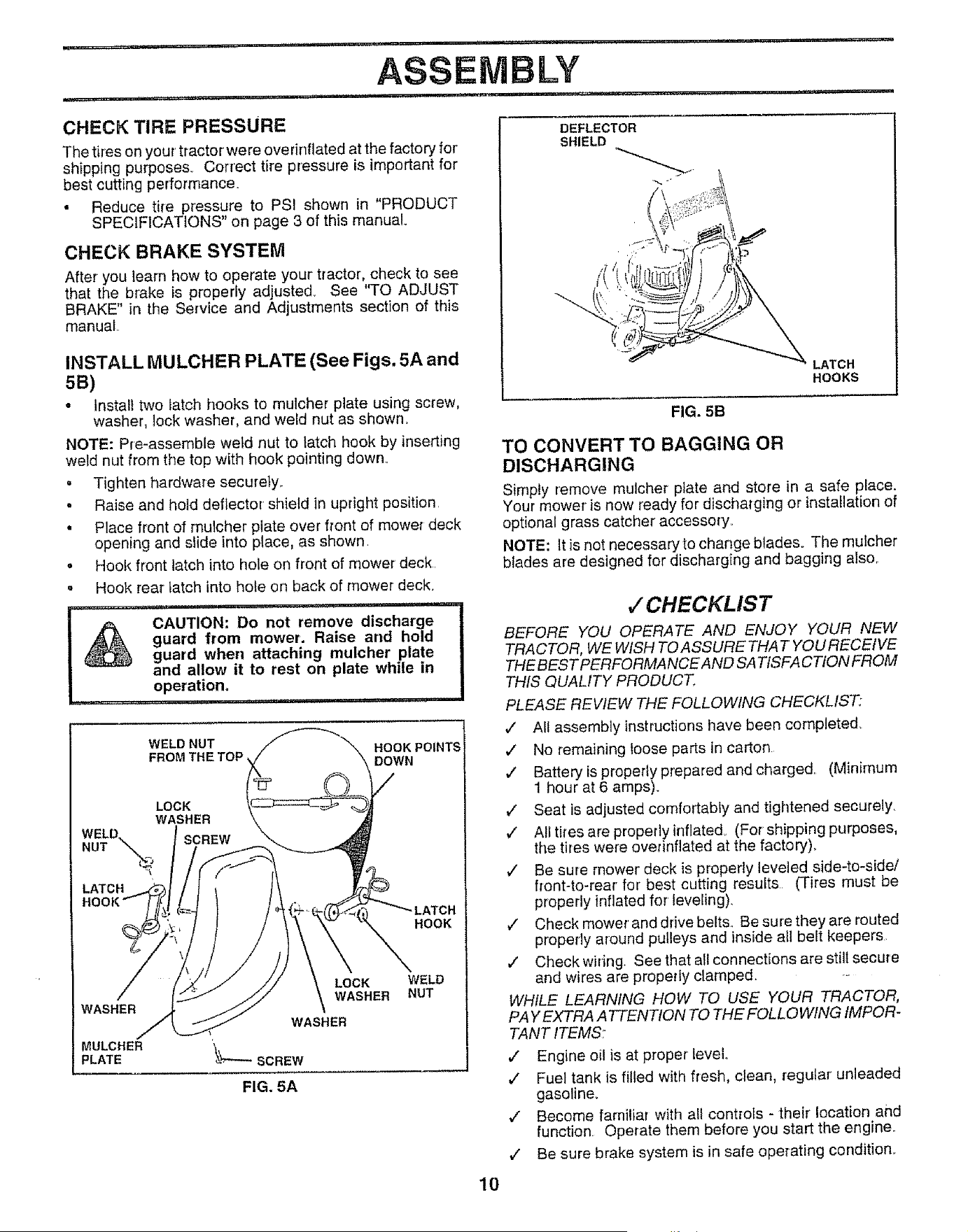
INSTALL MULCHER PLATE (See Figs. 5A and
5B)
- Install two latch hooks to mulcher plate using screw,
washer, lock washer, and weld nut as shown.
NOTE: Pre-assemble weld nut to latch hook by inserting
weld nut from the top with hook pointing down..
= Tighten hardware securety_
• Raise and hold deflector shield in upright position.
• Place front of mulcher plate over front of mower deck
opening and slide into place, as shown.
• Hook front latch into hole on front of mower deck.
° Hook rear latch into hole on back of mower deck.
....... ............... ..... i ,l!lll, i ,i,,L
CAUTION: Do not remove discharge
guard from mower. Raise and hold
guard when attaching mulcher plate
and allow it to rest on plate while in
operation°
..... = ,,i t
WELD NUT
LOCK
WASHER
WELD.
NUT "_.
LATCH
HOOKPOINTS!
DOWN
HOOK
WASHER
MULCHER
PLATE
LOCK
WASHER
WASHER
\ V----scREw
FIG. 5A
WELD
NUT
DEFLECTOR
SHIELD
//
LATCH
HOOKS
FIG. 5B
TO CONVERT TO BAGGING OR
DISCHARGING
Simply remove mulcher prate and store in a safe place.
Your mower is now ready for discharging or installation of
optional grass catcher accessory.
NOTE: It is not necessary to change btadeso The mulcher
blades are designed for discharging and bagging also..
,/CHECKLIST
BEFORE YOU OPERATE AND ENJOY YOUR NEW
TRACTOR, WE WISH TO ASSURE THAT YOU RECEIVE
THE BEST PERFORMANCE AND SA TtSFA CTION FROM
THIS QUALITY PRODUCT_
PLEASE REVIEW THE FOLLOWING CHECKLIST;
,/ All assembly instructions have been completed_
,/ No remaining loose parts in carton
,/ Batteryis proper{yprepared and charged. (Minirnum
1 hour at 6 amps).
,/ Seat is adjusted comfortably and tightened securely.
,/ All tires are properly inflated° (For shipping purposes,
the tires were overinflated at the factory).
,/ Be sure rnower deck is properly leveled side-to-side/
front-to-rear for best cutting results (Tires must be
properly inflated for' leveling).
v' Check mower'and drive belts. Be sure they are routed
properly around pulleys and inside all belt keepers
,/ Checkwiring. See that all connections are still secure
and wires are properly clamped. ._
WHILE LEARNING HOW TO USE YOUR TRACTOR,
PA Y EXTRA A TTENTION TO THE FOL L OWING IMPOR-
TANT ITEMS:
,/ Engine oil is at proper leveL.
v" Fuel tank is filled with fresh, clean, regular unleaded
gasoline,
,/ Become familiar with a!l controls - their location and
function Operate them before you start the engine_
v" Be sure brake system is in safe operating condition..
10
OPERATION
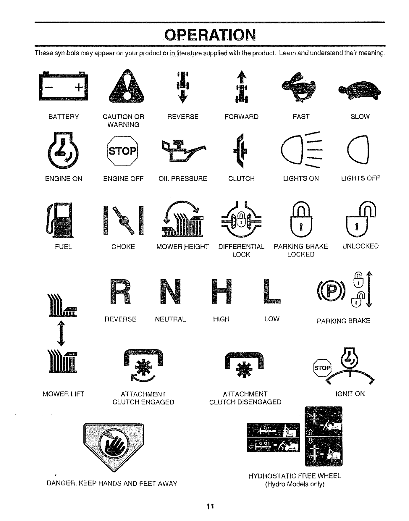
These symbols may appear on your product or in!iterat.ure supplied withthe product. Learn and understand their meaning.
E:3&
BATTERY CAUTION OR REVERSE FORWARD SLOW
WARNING
ENGINE ON ENGINE OFF OIL PRESSURE CLUTCH LIGHTS OFF
FAST
LIGHTS ON
!\l m
FUEL CHOKE MOWER HEIGHT
DIFFERENTIAL PARKING BRAKE UNLOCKED
LOCK LOCKED
MOWER LIFT
REVERSE NEUTRAL
ATTACHMENT
CLUTCH ENGAGED
L
HIGH LOW
ATTACHMENT
CLUTCH DISENGAGED
PARKING BRAKE
IGNITION
DANGER, KEEP HANDS AND FEET AWAY
HYDROSTATIC FREE WHEEL
(Hydro Models only)
11
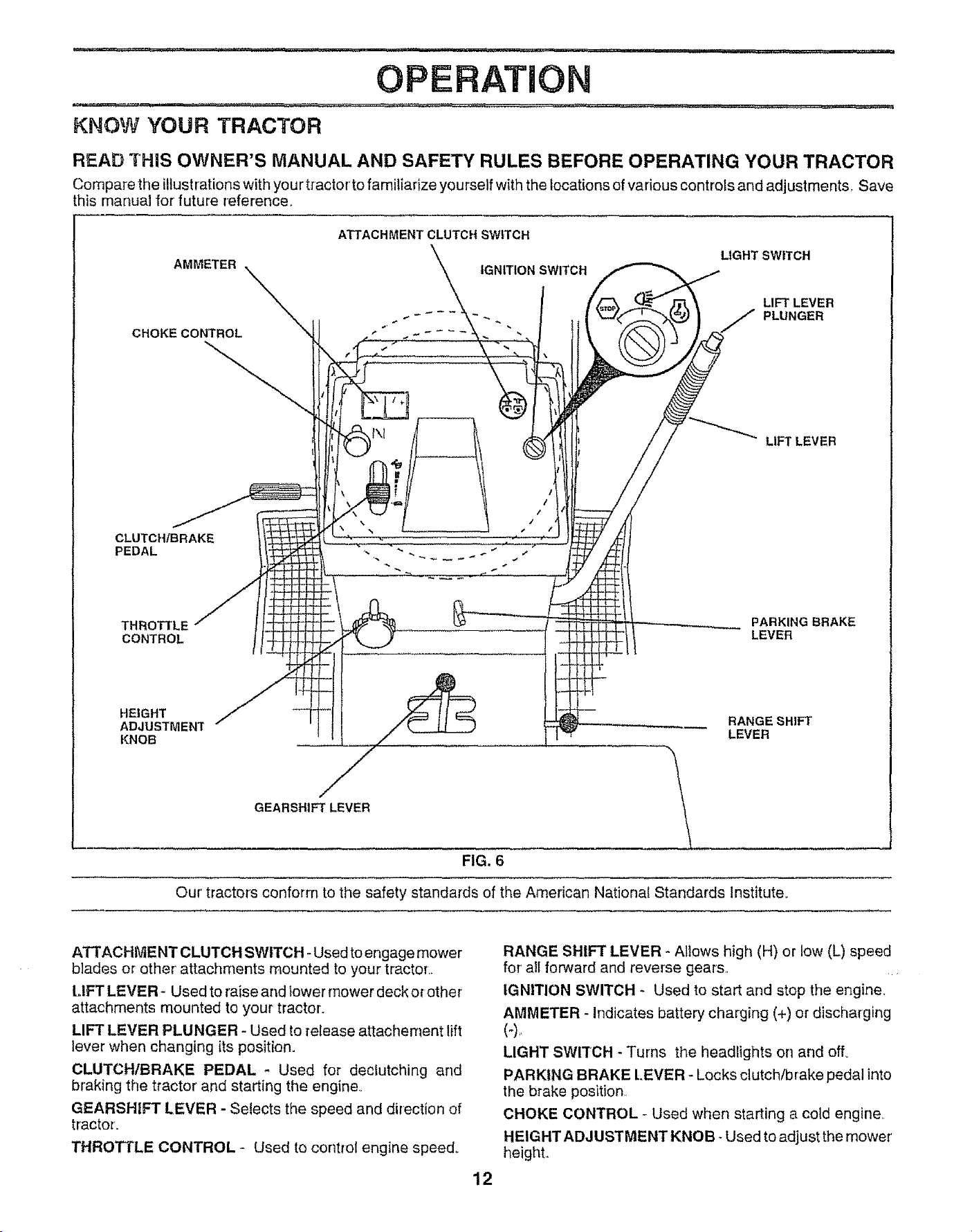
KNOW YOUR TRACTOR
,,, m.==- I,I,,H ......
OPERATION
READ THiS OWNER'S MANUAL AND SAFETY RULES BEFORE OPERATING YOUR TRACTOR
Compare the illustrations with your tractor'to familiarize yourself with the locations of vadous controls and adjustments_ Save
this manual for' future reference.
AMMETER
ATTACHMENT CLUTCH SWITCH
IGNITION SWITCH
LIGHT SWITCH
CHOKE CONTROL
CLUTCHtBRAKE
PEDAL
THROTTLE
CONTROL
LIFT LEVER
J PLUNGER
LIFT LEVER
PARKING BRAKE
LEVER
HEIGHT /_
ADJUSTMENT RANGE SHIFT
KNOB LEVER
GEARSHIFT LEVER _ ..........
FIG. 6
Our tractor's conform to the safety standards of the American National Standards Institute.
ATTACHMENT CLUTCH SWITCH ° Used to engage mower
blades or other' attachments mounted to your tractor.
LIFT LEVER- Used to raise and lower mower deck or other
attachments mounted to your tractor_
LIFT LEVER PLUNGER - Used to release attachement lift
lever when changing {Is position.
CLUTCH/BRAKE PEDAL - Used for dectutching and
braking the tractor and starting the engine,,
GEARSHIFT LEVER - Selects the speed and direction of
tractor.
THROTTLE CONTROL - Used to control engine speed_
12
RANGE SHIFT LEVER - Allows high (H) or low (L) speed
for all forward and reverse gears ....
IGNITION SWITCH - Used to start and stop the engine,
AMMETER - Indicates battery charging (+) or discharging
LIGHT SWITCH - Turns the headlights on and off°
PARKING BRAKE L.EVER - Locks clutch/brake pedal into
the brake position
CHOKE CONTROL - Used when starting a cold engine,
HEIGHT ADJUSTMENT KNOB - Used to adjust the mower'
heighL
,lUUlHI,IHII I n,m=n== = U == In =' ='=ram'=" I" inln I
OPERATION
=
=l,==u===lul,l=lu=,,,,i,ii, luuu,ii
Tile operation of any tractor can result in_f0reign objects thrown into the eyes, which can
result in severe eye damage° Always wear safety glasses or eye shields while operating
your tractor or performing any adjustments or repairs= We recommend a wide vision safety
mask over the spectacles or standard safety glasses.
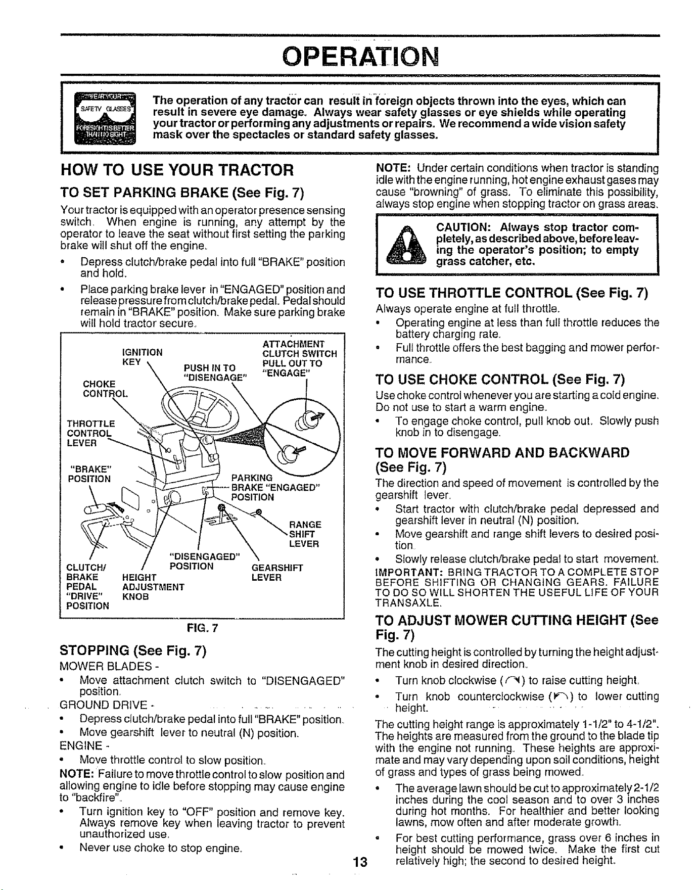
HOW TO USE YOUR TRACTOR
TO SET PARKING BRAKE (See Fig. 7)
Your tractor is equipped with an operator presence sensing
switch, When engine is running, any attempt by the
operator to leave the seat without first setting the parking
brake will shut off the engine.
= Depress clutch/brake pedal into full "BRAKE" position
and hol&
° Place parking brake lever in "ENGAGED" position and
release pressure from clutch/brake pedal. Pedal should
remain in BRAKE" position. Make sure parking brake
will hold tractor secure
ATTACHMENT
IGNITION CLUTCH SWITCH
KEY PUSHINTO PULLOUTTO
"DISENGAGE" "ENGAGE"
CHOKE
CONTROL
THROTTLE
CONTROL
LEVER
"BRAKE"
POSITION
RANGE
SHIFT
LEVER
"DISENGAGED"
CLUTCH/ POSITION GEARSHIFT
BRAKE HEIGHT LEVER
PEDAL ADJUSTMENT
"DRIVE" KNOB
POSITION
FIG. 7
STOPPING (See Fig. 7)
MOWER BLADES -
= Move attachment clutch switch to "DISENGAGED"
position,.
GROUND DRIVE ...............
• Depress clutch/brake pedal into full "BRAKE" position.
° Move gearshift lever to neutral (N) position.
ENGINE -
= Move throttle control to slow position.
NOTE: Failure to move throttle control to slow position and
altowing engine to idle before stopping may cause engine
to "backfire".
* Turn ignition key to "OFF" position and remove key.
Always remove key when leaving tractor to prevent
unauthorized use,
• Never' use choke to stop engine°
13
NOTE: Under certain conditions when tractor is standing
idle with the engine running, hot engine exhaust gases may
cause "browning" of grass. To eliminate this possibility,
always stop engine when stopping tractor on grass areas.
CAUTION: Always stop tractor com-
pletely, as described above, before leav-
ing the operator's position; to empty
grass catcher, etc.
TO USE THROTTLE CONTROL (See Fig, 7)
Always operate engine at full throttle.
° Operating engine at less than full throttle reduces the
battery charging rate.
= Full throttle offers the best bagging and mower perfor-
rnance.
TO USE CHOKE CONTROL (See Fig. 7)
Use choke control whenever you are starting a cold engine,
Do not use to start a warm engine.
• To engage choke control, pull knob out., Slowly push
knob in to disengage.
TO MOVE FORWARD AND BACKWARD
(See Fig. 7)
The direction and speed of movement is controlled by the
gearshift lever.
• Start tractor with clutch/brake pedal depressed and
gearshift lever in neutral (N) position.
• Move gearshift and range shift levers to desired posi-
tion
• Slowly release clutch/brake pedal to start movement.
IMPORTANT: BRING TRACTOR TO A COMPLETE STOP
BEFORE SHIFTING OR CHANGING GEARS, FAILURE
TO DO SO WILL SHORTEN THE USEFUL LIFE OF YOUR
TRANSAXLE.
TO ADJUST MOWER CUTTING HEIGHT (See
Fig. 7)
The cutting height is controlled by turning the height adjust_
ment knob in desired direction°
° Turn knob clockwise (_) to raise cutting height.
• Turn knob counterclockwise (V"_)to lower cutting
height. _.........
The cutting height range is approximately t-1/2" to 4-1/2".
The heights are measured from the ground to the blade tip
with the engine not running° These heights are approxi-
mate and may vary depending upon soil conditions, height
of grass and types of grass being mowed.
• The averagelawn should be cut to approximately2-1/2
inches during the cool season and to over 3 inches
during hot months. For healthier and better looking
lawns, mow often and after moderate growth_
- For best cutting performance, grass over 6 inches in
height should be mowed twice. Make the first cut
relatively high; the second to desired height..
................. • , , ...................... i, "N"IHII L_"ll'l"l'll,' " II...... I"
OPERATiO
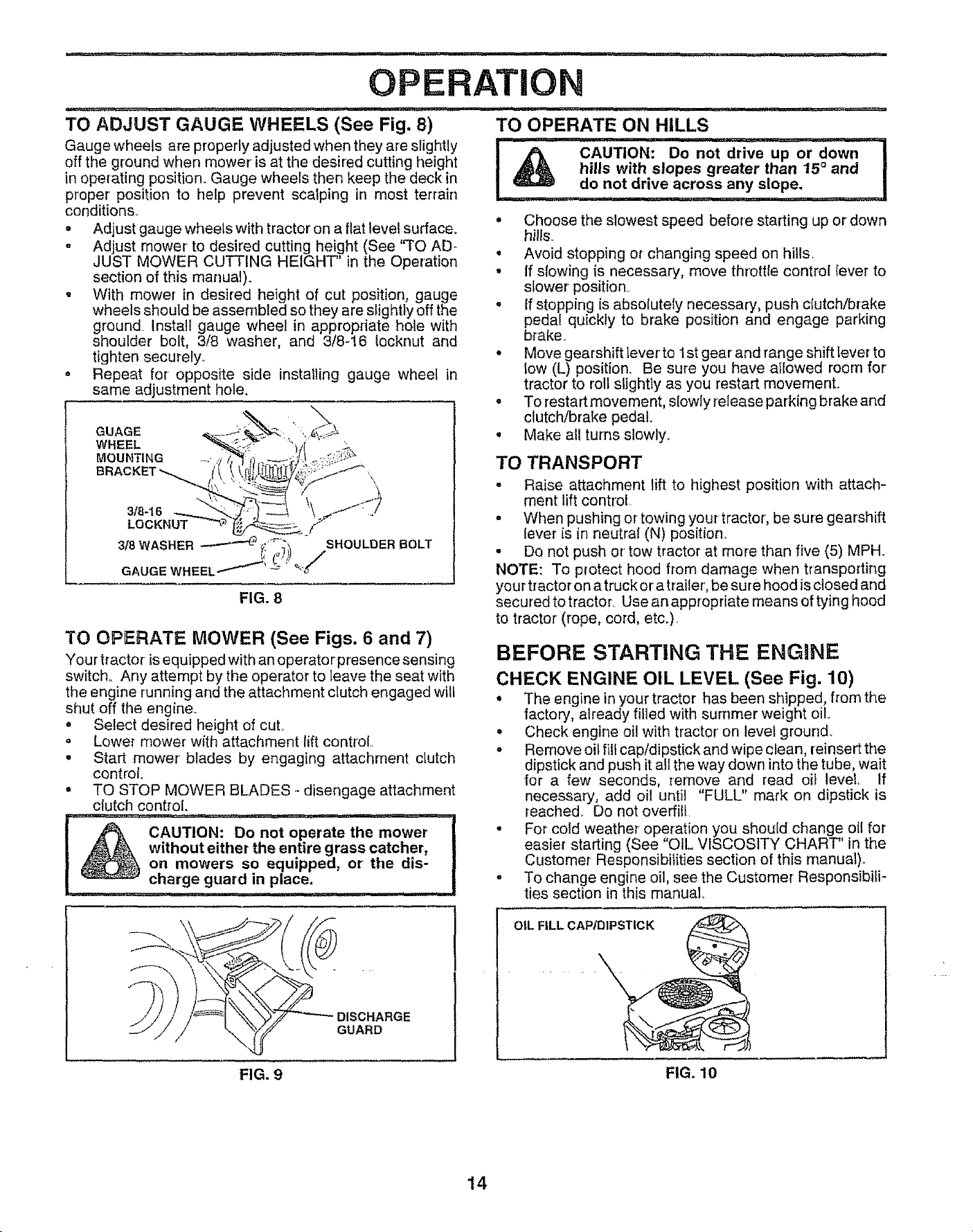
TO ADJUST GAUGE WHEELS (See Fig. 8)
Gauge wheels are properly adjusted when they are slightly
off the ground when mower is at the desired cutting height
in operating position. Gauge wheels then keep the deck in
proper position to help prevent scalping in most terrain
conditions.
= Adjust gauge wheels with tractor on a flat level surface.
. Adjust mower to desired cutting height (See 'q'O AD-
JUST MOWER CUTTING HEIGHT" in the Operation
section of this manual)°
. With mower in desired height of cut position, gauge
wheels should be assembled so they are slightly off the
ground Install gauge wheel in appropriate hole with
shoulder bolt, 3/8 washer, and 3/8-16 locknut and
tighten securely,,
o Repeat for opposite side installing gauge wheel in
same adjustment hole.
WHEEL
MOUNTING
FIG. 8
TO OPERATE MOWER (See Figs. 6 and 7)
Your tractor isequipped with an operator presence sensing
switch° Any attempt by the operator to leave the seat with
the engine running and the attachment clutch engaged will
shut off the engine,,
= Select desired height of cut°
• Lower mower with attachment lift control
. Start mower blades by engaging attachment clutch
control
• TO STOP MOWER BLADES - disengage attachment
clutch control.
TO OPERATE ON HILLS
I r)_ CAUTION: Do n0t_
hills with slopes greater than 15° and I
do not drive across any slope.
• Choose the slowest speed before starting up or down
hills_
° Avoid stopping or changing speed on hills.
° if slowing {s necessary, move throttle control tever to
slower position
o If stopping is absolutely necessary, push cfutch/brake
pedal quickly to brake position and engage parking
brake,
• Move gearshift tever to 1st gear and range shift lever to
low (L) position_ Be sure you have atlowed room for
tractor to roll slightly as you restart movement.
. To restart movement, slowly release parking brake and
clutch/brake pedal.
° Make all turns slowly,
TO TRANSPORT
- Raise attachment lift to highest position with attach-
ment lift control,
° When pushing or towing your tractor', be sure gearshift
lever {s in neutral (N) position,,
° Do not push or' tow tractor at more than five (5) MPH.
NOTE: To protect hood from damage when transporting
your tractor on a truck era trai letr,be sure hood isdosed and
secured to tractor_ Use an appropriate means oftying hood
to tractor (rope, cord, etc.),
BEFORE STARTING THE ENGINE
CHECK ENGINE OIL LEVEL (See Fig. 10)
. The engine in your tractor has been shipped, from the
factory, atready filled with summer weight oil
= Check engine oil with tractor' on level ground_
° Remove oil fill cap/dipstick and wipe clean, reinsertthe
dipstick and push it all the way down into the tube, wait
for a few seconds, remove and read oil level,. If
necessary, add oil until "FULL" mark on dipstick is
teached_ Do not overfill
. For cold weather' operat{on you should change oil for
easier starting (See "OIL VISCOSITY CHART" in the
Customer Responsibilities section of this manual),,
- To change engine oil, see the Customer Responsibili-
ties section in this manual,,
OIL FILL CAP/DIPSTICK
DISCHARGE
GUARD
FIG. 9
FIG. 10
14
.... IHHUU Ul ........................................ Ul
• OPERATI
................................................cO w H ..........
ADD GASOLINE LD EAT ER STARTING (50° F and below)
• Fill fuel tank, Use fresh, clean, regular unleaded . When engine starts, slowly push choke control in until
gasoline with a minimum of 87 octane.. (Use of leaded the engine begins to run smoothly. Continue to push
gasoline will increase carbon and lead oxide deposits the choke control in small steps alfowing the engine to
and reduce valve life). Do not mix oil with gasoline, accept small changes in speed and load, until the
Purchase fue! in quantities that can be used within 30 choke control is fully in, If the engine starts to run
days to assure fuel freshness° roughly, pull the choke control out slightly for a few
IMPORTANT; WHEN OPERATING tN TEMPERATURES seconds and then continue to push the control in
BELOW32°F(0"C), USE FRESH, CLEAN WINTER GRADE slowly.. This may require an engine warm-up period
GASOLINE TO HELP INSURE GOOD COLD WEATHER from several seconds to several minutes, depending
STARTtNG. on the temperature°
WARNING: Experience indicates that alcohol blended • The attachments can be used duringthe engine warm-
fuels (called gasohol or using ethanol or methanol) can up period and may require the choke control be pulled
attract moisture which leads to separation and formation of out slightly.
acids during storage. Acidic gas can damage the fuel NOTE: If at a high altitude (above 3000 feet) or in cold
system of an engine while in storage_ To avoid engine temperatures (below32 F)the carburetor fuel mixture may
problems, the fuel system should be emptied before stor- need to be adjusted for' best engine performance. See'TO
age of 30 days or longer. Drain the gas tank, start the ADJUST CARBURETOR" in the Service and Adjustments
engine and let it run until the fuel lines and carburetor' are section of this manual..
empty. Use fresh fuel next season.. See Storage Instruc-
tions for additional information.. Never use engine or
carburetor cleaner products in the fuel tank or permanent
damage may occur°
CAUTION: Fill to bottom of gas tank i
,_Jk filler neck. Do not overfill. Wipe offany !
spilled oil or fuel. Do not store, spill or |
use gasoline near an open flame. _____J
TO START ENGINE (See Fig, 7)
When starting the engine for the first time or if the engine
has run out of fuel, it will take extra cranking time to move
fuel from the tank to the engine.
', Sit on seat in operating position, depress clutch/brake
pedal and set parking brake
= Place gear shift lever in neutral (N) position.
. Move attachment clutch to "DISENGAGED" position.
o Move throttle control to fast position
* Pull choke control out for a cotd engine start attempt.
For a warm engine start attempt the choke control may
not be needed.
Note: Before starting, read the warm and cold starting
procedures below.
• Insert key into ignition and turn keyclockwise to"START"
position and release key as soon as engine starts_ Do
not run starter continuously for more than fifteen sec-
onds per minute. If the engine does not start after'
several attempts, push choke control in, wait a few
minutes and try again, tf engine still does not start, pull
the choke control out and retry°
WARM WEATHER STARTING (50° F and above)
= When engine starts, slowly push choke control in until
the engine begins to run smoothly, If the engine starts
to run roughly, pull the choke control out slightly for a
few seconds and then continue to push the control in
slowly..
o The attachments and ground drive can now be used_ If
the engine does not accept the load, restart the engine
and allow it to warm up for one minute using the choke
as described above
MOWING TIPS
° Tire chains cannot be used when the mower •housing
is attached to tractor.
o Mower should be properly leveled for' best mowing
performance. See ''TO LEVEL MOWER HOUSING" in
the Service and Adjustments section of this manual.
o The left hand side of mower' should be used for trim-
ming.
• Drive so that clippings are discharged onto the area
that has been cut. Have the cut area to the right of the
machine. This will result in a more even distribution of
clippings and more uniform cutting
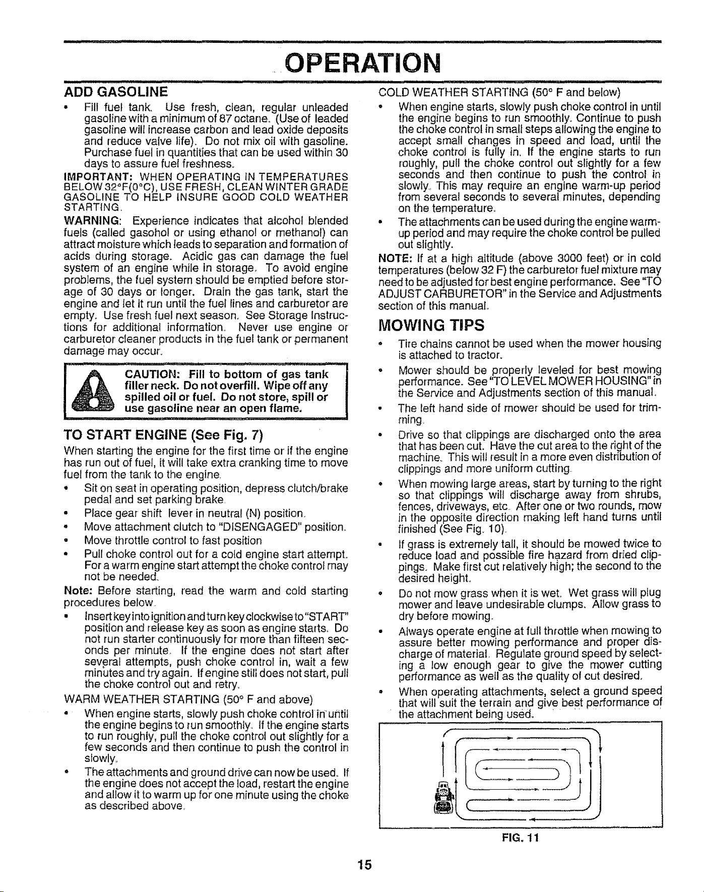
• When mowing large areas, start by turning to the right
so that clippings will discharge away from shrubs,
fences, driveways, etc After one or two rounds, mow
in the opposite direction making left hand turns until
finished (See Fig. 10).
• If grass is extremely tall, it should be mowed twice to
reduce load and possible fire hazard from dried clip*
pings. Make first cut relatively high; the second to the
desired height°
o Do not mow grass when it is wet° Wet grass will plug
mower and leave undesirable clumps. Allow grass to
dry before mowing..
- Always operate engine at full throttle when mowing to
assure better mowing performance and proper dis-
charge of material, Regulate ground speed by select-
ing a low enough gear' to give the mower cutting
performance as wet!l as the quality of cut desired.
° When operating attachments, select a ground speed
that will suit the terrain and give best performance of
the attachment being used. " ......
f
J
FIG. 11
15
OPERATION
MULCHaNG MOWING TIPS
IMPORTANT: FOR BEST PERFORMANCE, KEEP
MOWER HOUSING FREE OF BUILT-UP GRASS AND
TRASH CLEAN AFTER EACH USE
- The special mu_ching blade will recut the grass clip-
pings many times and reduce them in size so that as
they fall onto the lawn they wilt disperse intothe grass
and not be noticed. Also, the mulched grass wil!
biodegrade quickly to provide nutrients for' the lawn.
Always mulch with your highest engine (blade) speed
as this will provide the best recutting action of the
blades.
- Avoid cutting your lawn when it iswet. Wet grass tends
to form clumps and interferes with the mulching action.
The best time to mow your lawn is the early afternoon
At this time the grass has dried and the newly cut area
will not be exposed to the direct sun.
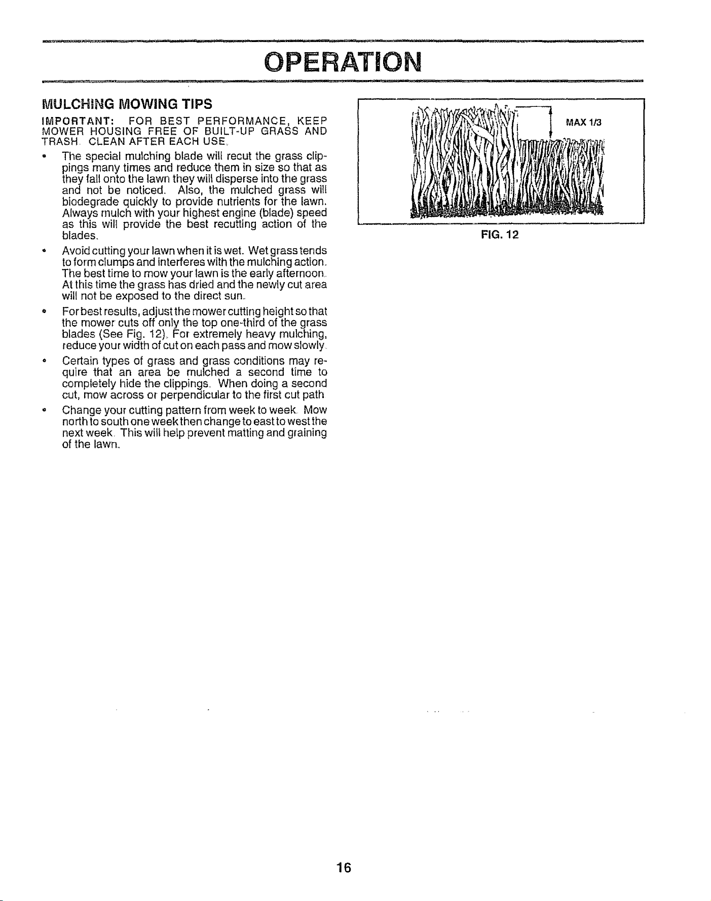
= For'best results, adjust the mower cutting height so that
the mower cuts off only the top one-third of the grass
blades (See Fig. 12)_ For extremely heavy mulching,
reduce your width of cut on each pass and mow slowly
o Certain types of grass and grass conditions may re-
quire that an area be mulched a second time to
completely hide the clippings. When doing a second
cut, mow across or perpendicular to the first cut path
o Change your cutting pattern from week to week Mow
north to south one weekthen change to east to west the
next week This will help prevent matting and graining
of the lawn.
MAX 1/3
FIG. 12
16
iiiiiiiii iiiii,i iii ,llllllll iii
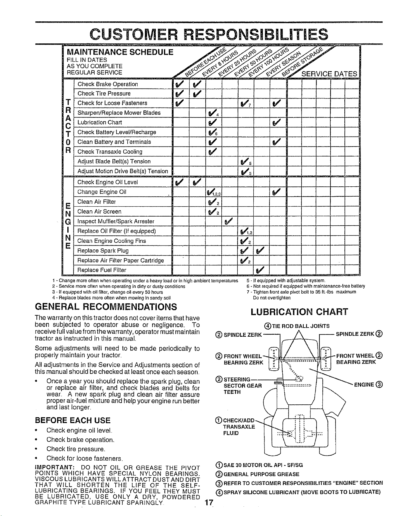
CUSTOM RESPONSIBILITIES
FILL IN DATES /___.._r
AS COMPLETE
REGULAR RV,CE DATES
Check Brake Operation ..............tf !/ , , , I
T
0
R_
Check Tire Pressure
Check for Loose Fasteners
Sharpen/Replace Mower Blades
Lubrication chart
Check Battery Level/Recharge
Clean Battery and Terminals
v' v'
v' v', ..........v'
1/4
Check Transaxle Cooling
Adjust Blade Belt(s) Tension 6#_'s
Adjust Motion Drive Belt(s) Tension _5i
Check Engine Oii Level = _#' ' _ '
Change Engine Oi! ......._........... i,,,_1,2,3
i E Clean Air Filter $/'2
i N Clean Air Screen
G ; ,,In,spect Muffler/Spark Arrestor
Replace Oil Filter (if equipped) _.2
clean Engine cooling Fins _I _21
E Replace spaiii Plug " _
Replace Air Filter Paper Cartridge " _#_'2
Replace Fue Fi ie'r................................................................................ If
1 - Change more often when operating under a heaw load or in high ambient temperatures
v"
................ t....
1 .....
5 ,. ffequipped with adjustable system,
2 - Service more often when epe_'aling in dirty or dusty conditions
3 - If equipped with oil filler, change el! every 50 hours
4 - Replace blades more oiten when mewing in sandy soil
GENERAL RECOMMENDATIONS
The warranty on this tractor does not cover items that have
been subjected to operator' abuse or negligence° To
receive full value from the warranty, operator must maintain
tractor as instructed in this manual.
6 - Not required if equipped with maintenance-lree battery
7 - Tighlen front axle pivot bolt to 35 i't -Ibs maximum
Do not overtighten
LUBRICATION CHART
(_) SPINDLE
(_)TIE ROD BALL JOINTS
SPINDt.E ZERK (_
Some adjustments will need to be made periodically to
properly maintain your tractor,
All adjustments in the Service and Adjustments section of
this manual should be checked at least once each season,
• Once a year you should replace the spark plug, clean
or replace air filter, and check blades and belts for
wearL A new spark plug and clean air filter assure
proper air-fuel mixture and help your engine run better
and test longer,
(_) FRONT IT WHEEL (_)
BEARING ZERK BEARING ZERK
(_) STEERING
SECTOR GEAR ENGINE (_
TEE'IH
BEFORE EACH USE
• Check engine oil level
. Check blake operation,
• Check tire pressure,
• Check for loose fasteners,
IMPORTANT: DO NOT OIL OR GREASE THE PIVOT
POINTS WHICH HAVE SPECIAL NYLON BEARINGS.
VISCOUS LUBRICANTS WILL ATTRACT DUST AND DIRT
THAT WILL SHORTEN THE LIFE OF THE SELF-
LUBRICATING BEARINGS. IF YOU FEEL THEY MUST
BE LUBRICATED, USE ONLY A DRY, POWDERED
GRAPHITE TYPE LUBRICANT SPARINGLY
i_) CHECK/ADD",.
TRANSAXLE
FLUID
(_SAE 30 MOTOR OIL API - SF/SG
(_) GENERAL PURPOSE GREASE
(_) REFER TO CUSTOMER RESPONSIBILITIES "ENGINE" SECTION
(_SPRAY SILICONE LUBRICANT (MOVE BOOTS TO LUBRICATE)
17
CUSTOM LITtES
...... , ,, , Ull,ii ....... i, i1,1 ,! , ,.... Ul................... i
TRACTOR o The blade can be sharpened with a file or on a grinding
wheel, Do not attempt to sharpen while on the mower_
Always observe safety rules when performing any mainte-
nance_
BRAKE OPERATION
if unit requires more than six (6) feet stopping distance at
high speed in highest gear, then brake must be adjusted..
(See 'q'O ADJUST BRAKE" in the Service and Adjust-
ments section of this manual).
TIRES
° Maintain proper air pressure in all tires (See "PROD-
UCT SPECIFICATIONS" on page 3 of this manual)..
° Keep tires free of gasoline, oil, or' insect control chemi-
cals which can harm rubber'.
o Avoid stumps, stones, deep ruts, sharp objects and
other hazards that may cause tire damage.
NOTE: To seal tire punctures and prevent fiat tires due to
slow leaks, tire sealant may be purchased from your local
parts dealer. Tire sealant also prevents tire dry rot and
corrosion.
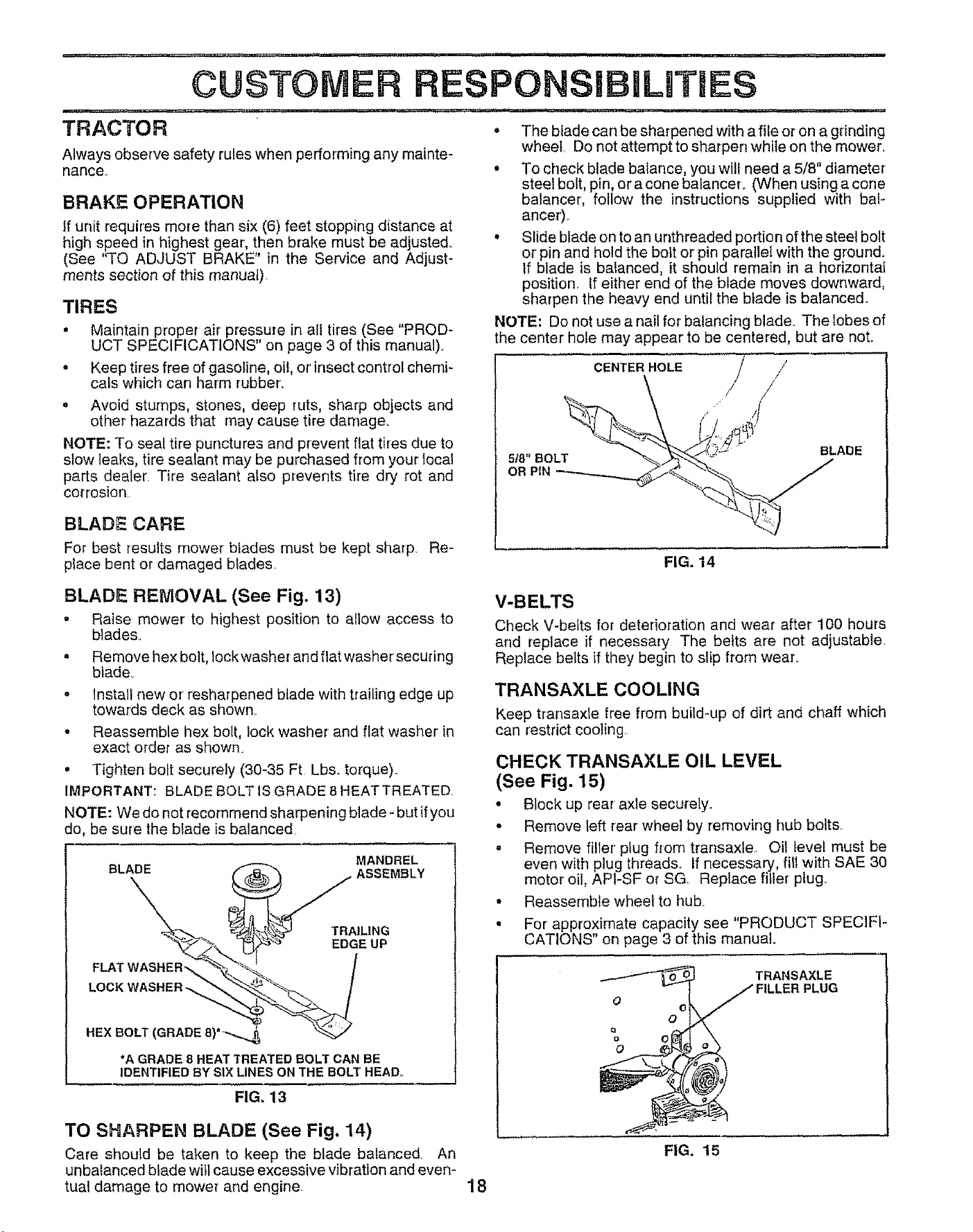
• To check blade balance, you will need a 5/8" diameter'
steel bolt, pin, or a cone balanceL (When using a cone
balancer, follow the instructions supplied with bal-
ancer).
° Slide blade on to an unthreaded portion of the steel bolt
or pin and hold the bolt or pin parallel with the ground.
if blade is balanced, it should remain in a horizontal
position., tf either end of the blade moves downward,
sharpen the heavy end until the blade is balanced..
NOTE: Do not use a nail for balancing blade. The lobes of
the center hole may appear to be centered, but are not.
BLADE CARE
For best results mower blades must be kept sharp. Re-
place bent or damaged blades,
CENTER HOLE /
FIG. 14
BLADE REMOVAL (See Fig. 13)
- Raise mower to highest position to allow access to
blades,
° Remove hex bolt, fockwasher and fiat washer secudng
blade,
. Install new or resharpened blade with trailing edge up
towards deck as shown.
• Reassemble hex bolt, lock washer and flat washer in
exact order as shown.
• Tighten bolt securely (30-35 Ft Lbs. torque),.
IMPORTANT: BLADE BOLT lS GRADE 8 HEATTREATED,
NOTE: We do not recommend sharpening blade - but if you
do, be sure the blade is balanced,
MANDREL
LOCKWASHER-._ _ ._""_.
HEX O,T(GRADEa)
*A GRADE 8 HEAT TREATED BOLT CAN BE
IDENTIFIED BY SIX LINES ON THE BOLT HEAD.
FIG. 13
TO SHARPEN BLADE (See Fig. 14)
Care should be taken to keep the blade balanced An
unbalanced blade will cause excessive vibration and even-
tual damage to mower and engine
V-BELTS
Check V-belts for deterioration and wear after 100 hours
and replace if necessary The belts are not adjustable
Replace belts if they begin to slip from wear_
TRANSAXLE COOLING
Keep transaxle free from build-up of dirt and chaff which
can restrict cooling.
CHECK TRANSAXLE OIL LEVEL
(See Fig. 15)
• Block up rear' axle securely..
• Remove left rear wheel by removing hub bolts_
- Remove filler' plug from transaxle.. Oil level must be
even with plug threads. If necessary, fill with SAE 30
motor oil, API-SF or SG Replace filler plug.
• Reassemble wheel to hub.
• For approximate capacity see "PRODUCT SPECIFI-
CATIONS" on page 3 of this manual.
o oi
O
O
TRANSAXLE
PLUG
FIG. 15
18
N,H=,,NII==
CUSTOMER
BAKERY
Your tractor has a battery charging system which is suffi-
cient for normal use. However, periodic charging of the
battery with an automotive charger' will extend its life.
, Keep battery and terrninals clean.
° Keep battery bolts tight.
• Keep small vent holes open.
, Recharge at 6-10 amperes for I hour.
TO CLEAN BATTERY AND TERMINALS
Corrosion and dirt on the battery and terminals can cause
the battery to "leak" power'.
• Remove terminal guard.
• Disconnect BLACK battery cable first then RED bat-
tery cable and remove battery from tractor.
° Rinse the battery with plain water and dry°
• Clean terminals and battery cable ends with wire brush
until bright°
, Coat terminals with grease or petroleum jelly.
• Reinstall battery (See "CONNECT BATTERY" in the
Assernbiy section of this manual)..
ENGINE
LUBRICATION
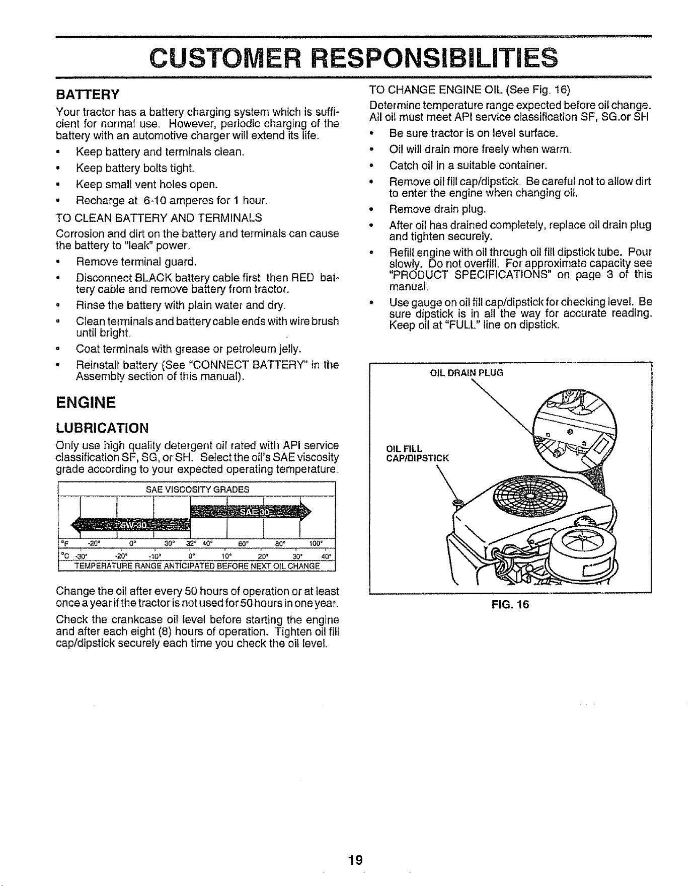
Only use high quality detergent oii rated with API service
classification SF, SG, or SH. Select the oil's SAE viscosity
grade according to your expected operating temperature.
SAE VISCOSITY GRADES
_F "20° 0= 30 _ 32_ 40° 60° 80" 100°
TEMPE.ATU.E.A.GEA.T CtPATED.EFO.E.EXT C.A.GE
Change the oil after every 50 hours of operation or' at least
once a year ifthe tractor'is not used for 50 hours in one year.
Check the crankcase oil level before starting the engine
and after each eight (8) hours of operation_ Tighten oil fill
cap/dipstick securely each time you check the oil level
i i = i IIINII ,III=III=,INIII,III=
RESPONSIBiLITiES
TO CHANGE ENGINE OIL (See Fig. 16)
Determine temperature range expected before oil change.
All oil must meet API service classification SF, SG.or SH
• Be sure tractor is on level surface°
- Oil wilt drain more freely when warm.
• Catch oil in a suitable container°
• Remove oil fill cap/dipstick. Be careful not to allow dirt
to enter the engine when changing oil.
° Remove drain plug.
• After oil has drained completely, replace oil drain plug
and tighten securely°
,, Refill engine with oil through oil fill dipstick tube. Pour'
slowly. Do not overfill° For approximate capacity see
PRODUCT SPECIFICATIONS on page 3 of this
manual
• Use gauge on oii fill cap/dipstick for checking level. Be
sure dipstick is in all the way for accurate reading.
Keep oil at "FULL" line on dipstick.
OIL DRAIN PLUG
OIL FILL
CAP,/DIPSTiCK
FIG. 16
19
CUSTOM
................ ,.... , i, i,iiii
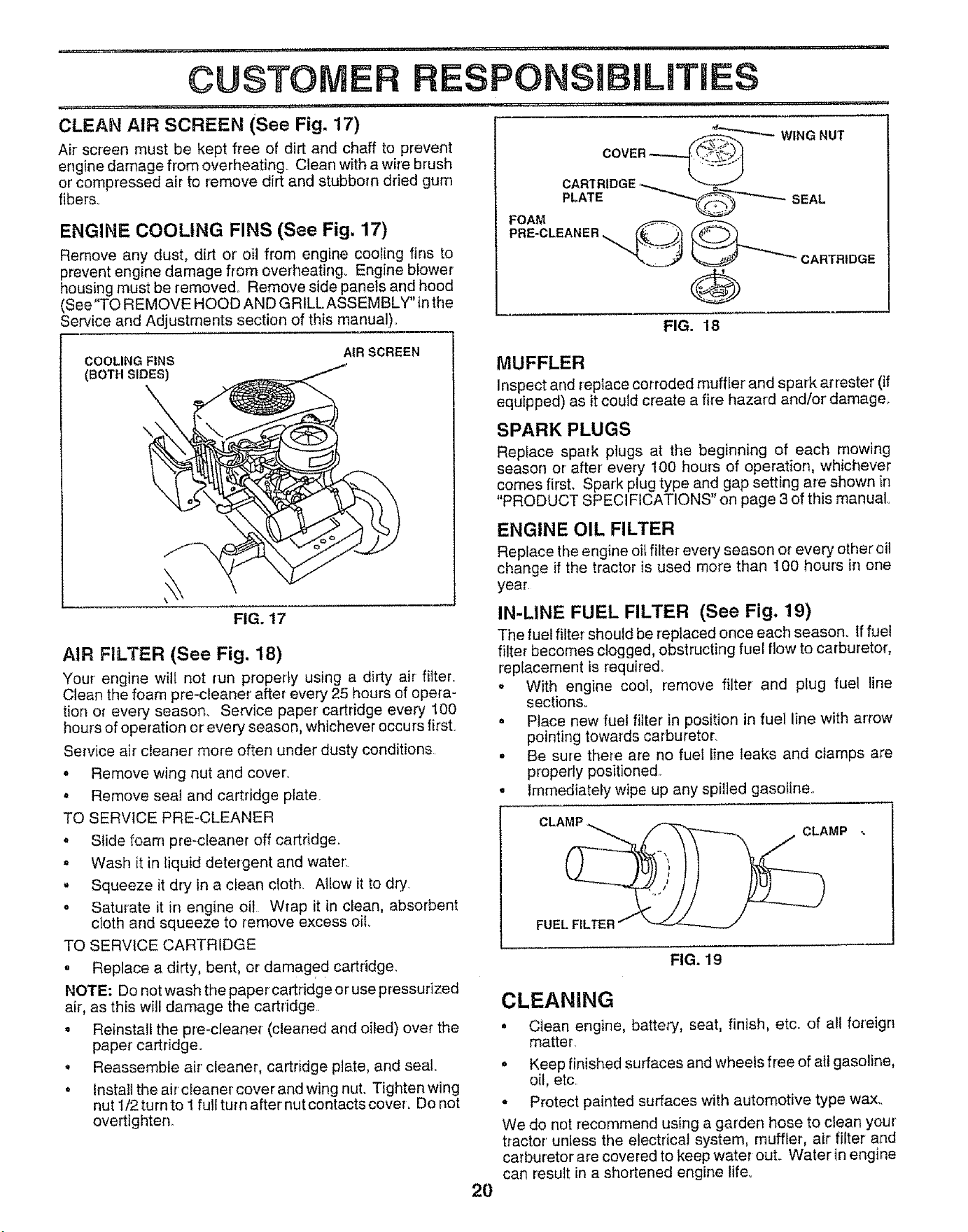
CLEAN AIR SCREEN (See Fig. 17)
Air screen must be kept free of dirt and chaff to prevent
engine damage from overheating Clean with a wife brush
or compressed air to remove dirt and stubborn dried gum
fibers_
PONSIBILJTIES
i,,i,,,, ,.......
FOAM
_ WING NUT
CARTRIDGE '___
.LATE SEAL
ENGINE COOLING FINS (See Fig. 17)
Remove any dust, dirt or oil from engine cooling fins to
prevent engine damage from overheating. Engine blower
housing must be removed. Remove side panels and hood
(See"TO REMOVE HOOD AND GRILLASSEMBLY" in the
Service and Adjustments section of this manual)
PRE-CLEANER
__ CARTRIDGE
FIG. 18
COOLING FINS
(BOTH SIDES)
AIR SCREEN
\
FIG. 17
AIR FILTER (See Fig. 18)
Your engine wilt not run properly using a dirty air filter_
Clean the foam pre-cleaner after every 25 hours of opera-
tion or every seasorL Service paper cartridge every !00
hours of operation o reve ry season, whichever occurs first
Service air cieaner more often under dusty conditions
• Remove wing nut and cover.
= Remove seal and cartridge plate
TO SERVICE PRE-CLEANER
= Slide foam pre-cleaner off cartridge_
• Wash it in liquid detergent and water:
. Squeeze it dry in a dean cloth Allow it to dry
• Saturate it in engine oil Wrap it in clean, absorbent
cloth and squeeze to remove excess oiL
TO SERVICE CARTRIDGE
o Replace a dirty, bent, or damaged cartridge.
NOTE: Do not wash the papercartddge or use pressurized
air, as this will damage the cartridge
. Reinstall the pre-cleaner (cleaned and oiled) over the
paper cartridge
. Reassemble air cleaner, cartridge plate, and seal.
• Install the air cleaner cover and wing nut. Tighten wing
nut 1/2 turn to 1 full turn after nut contacts coveL Do not
overtighten.
MUFFLER
Inspect and replace cor reded muffler and spark arrester (if
equipped) as it could create a fire hazard and/or damager
SPARK PLUGS
Replace spark plugs at the beginning of each mowing
season or after' every 100 hours of operation, whichever
comes first, Spark plug type and gap setting are shown in
"PRODUCT SPECl FICATIQNS" on page 3 of this manual,
ENGINE OIL FILTER
Replace the engine oil filter every season or every other oil
change if the tractor is used more than 100 hours in one
year
IN-LINE FUEL FILTER (See Fig, 19)
The fuel filter should be replaced once each season. If fue!
filter becomes dogged, obstructing fuel flow to carburetor,
replacement is required
o With engine cool, remove filter and plug fuel line
sections_
• Place new fue! filter in position in fuel line with arrow
pointing towards carburetor.
• Be sure there are no fuel line leaks and clamps are
properly positioned
• Immediately wipe up any spilled gasoline
CLAMP, CLAMP
FUEL FILTER
FIG. 19
CLEANING
° Clean engine, battery, seat, finish, etCr of all foreign
matter
. Keep finished surfaces and wheels free of all gasoline,
oil, etc_
- Protect painted surfaces with automotive type wax,.
We do not recommend using a garden hose to clean your
tractor unless the electrical system, muffler, air filter and
carburetor are covered to keep water out Waterin engine
can result in a shortened engine life.
2O
SERVICE AN ADJUSTMENTS
e
_IL'HH_L'I//, '1",,', I
CAUTION: BEFORE PERFORMING ANY SERVICE OR ADJUSTMENTS:
Depress clutcWbrake pedal fully and set parking brake.
Place gearshift lever in neutral (N) position.
Place attachment clutch in ='DISENGAGED" position.
Turn ignition key "OFF" and remove key.
Make sure the blades and all moving parts have completely stopped.
Disconnect spark plug wire from spark plug and place wire where it cannot come in contact
with plug.
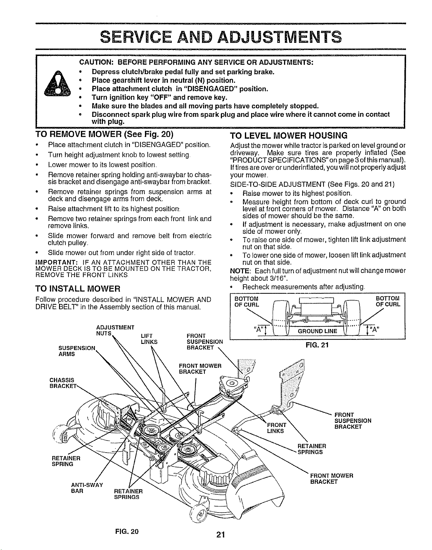
TO REMOVE MOWER (See Fig. 20)
, Place attachment clutch in "DISENGAGED" position.
, Turn height adjustment knob to lowest setting
• Lower mower' to its lowest position,
° Remove retainer spring holding anti-swaybar to chas-
sis bracket and disengage anti-swaybar from bracket.
• Remove retainer springs from suspension arms at
deck and disengage arms from deck.
• Raise attachment lift to its highest positiort.
• Remove two retainer springs from each front lir_kand
remove links.
• Slide mower forward and remove belt from electric
clutch puley.
• Slide mower out from under right side of tractor.
IMPORTANT: IF AN ATTACHMENT OTHER THAN THE
MOWER DECK !S TO BE MOUNTED ON THE TRACTOR,
REMOVE THE FRONT LINKS
TO INSTALL MOWER
Foiow procedure described in "INSTALL MOWER AND
DRIVE BELT" in the Assembly section of this manual.
su£
ARMS
ADJUSTMENT
LIFT FRONT
LINKS SUSPENSION
BRACKET
BRACKET
........................ i
ii, ,,i,,, ,i _,_,,,i,1,, i ..... i
TO LEVEL MOWER HOUSING
Adjust the mower' while tractor is parked on level ground or
driveway, Make sure tires are properly inflated (See
"PRODUCT SPECIFICATIONS" on page 3 of this manual).
Iftires are over' or'underinftated, you wil not properly adjust
your mower.
SIDE-TO*SIDE ADJUSTMENT (See Figs. 20 and 21)
o Raise mower to its highest position.
= Measure height from bottom of deck cud to ground
leve! at front corners of mower. Distance "A" on both
sides of mower should be the same.
* If adjustment is necessary, make adjustment on one
side of mower only.
- To raise one side of mower, tighten lift link adjustment
nut on that side.
, To lower one side of mower, loosen lift link adjustment
nut on that side.
NOTE: Each full turn of adjustment nut will change mower
height about 3/16".
, Recheck measurements after adjusting°
BOTTOM BOTTOM
OF C__ CURL
FIG, 21
CHASSIS
BRACKET_
RETAINER
SPRING
ANTI-SWAY
BAR
RETAINER
SPRINGS
FRONT
SUSPENSION
BRACKET
RETAINER
SPRINGS
FRONT MOWER
BRACKET
FIG. 20 21
.... ; ,,, ,, _ ................ ,........................ i ¸ in,ll
SERVICE AN
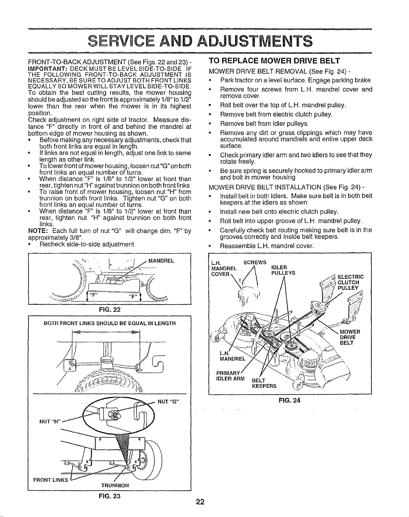
FRONT-TO-BACK ADJUSTMENT (See Figs, 22 and 23) -
IMPORTANT; DECK MUST BE LEVEL SIDE-TO*SIDE IF
THE FOLLOWING FRONT-TO-BACK ADJUSTMENT IS
,T ........... " ,,," ,""," , ..................... i,,,
ADJUSTMENTS
.......... _, ,, i ,111, , ii t, , i, ,i, ,,i, i! tl i
TO REPLACE MOWER DRWE BELT
MQWER DRIVE BELT REMQVAL (See Fig. 24) -
NECESSARY, BE SURE TO ADJUST BOTH FRONT LINKS
EQUALLY SO MOWER WILL STAY LEVEL SIDE-TO-SIDE
To obtain the best cutting results, the mower housing
should be adjusted so the front is approximately 1/8" to 1/2"
lower than the rear when the mower is in its highest
position.
Check adjustment on right side of tractor., Measure dis-
tance "F' directly in front of and behind the mandrel at
bottom edge of mower housing as shown.
• Before making any necessary adjustments, checkthat
both front links are equal in tength_
• If links are not equat in length, adjust one link to same
length as other link.
° To lowerfront of mower housing, loosen nut"G'on beth
front links an equal number of turns.
. When distance "F" is t/8" to 1/2" lower at front than
. Park tractor on a level surface. Engage parking brake
• Remove four screws from L,H, mandrel cover' and
remove covef.
. Roll belt over the top of LH. mandrel pulley.
. Remove belt from electric clutch pulley.
• Remove belt from idler pulley&
• Remove any dirt or grass clippings which may have
accumulated around mandrels and entire upper deck
su trace.
. Check primary idler arm and two idlers to see that they
rotate freely.,
• Be sure spring is securely hooked to primary idler arm
and bolt in mower hous[ng
rear, tighten nut"H" against trunnion on both front links,
. To raise front of mower housing, {oosen nut "H" from
trunnion on both front links° Tighten nut "G" on both
front links an equal number of turns.
• When distance "F" is 1/8" to 1J2" lower at front than
rear, tighten nut "H" against trunnion on both front
links,
NOTE: Each full turn of nut "G" will change dim, "F" by
approximately 3/8".
o Recheck side-to-side adjustment,
MOWER DRIVE BELT INSTALLATION (See Fig, 24) -
• Install belt in both idlers° Make sure belt is {n both belt
keepers at the idlers as shown
° Install new belt onto electric clutch pulley°
o Roll belt into upper groove of LH mandrel pulley,.
• Carefully check belt routing making sure belt is in the
grooves correctly and inside belt keepers,
• Reassemble LH. mandrel cover.
_--.,:.':",-.%" Io .. j/MANDREL
_) fJ-
FIG. 22
LH. SCREWS
MANDREL
IDLER
PULLEYS
BOTH FRONT LINKS SHOULD BE EQUAL IN LENGTH
NUT "G"
NUT"H
FRONTLINKS
TRUNN|ON
FIG. 23
22
MANDREL
PI
IDLER ARM BELT
KEEPERS
MOWER
DRIVE
BELT
FIG. 24
HHHH='=HI INI
SERVICE AN ADJUSTMENTS
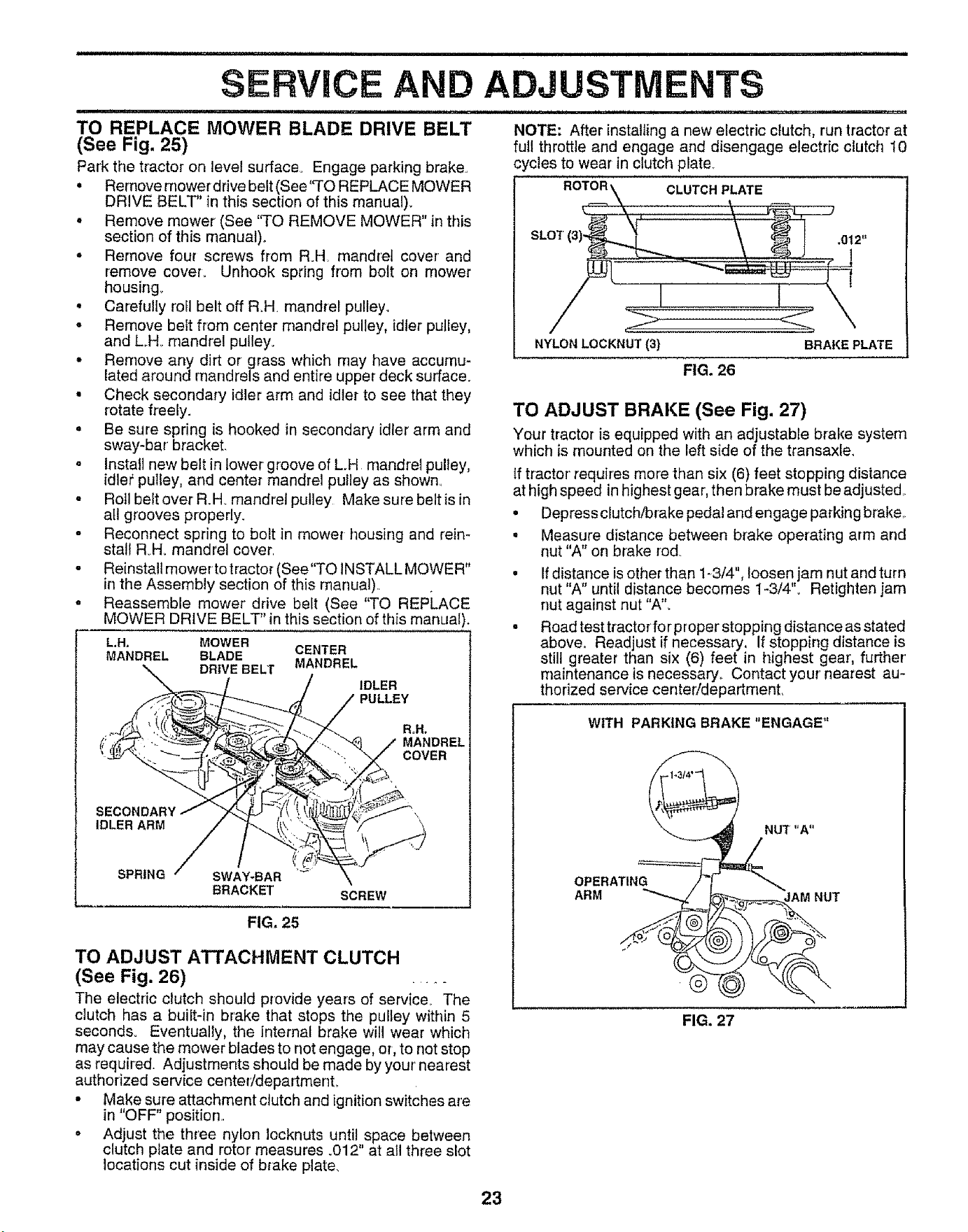
TO REPLACE MOWER BLADE DRIVE BELT
(See Fig. 25)
Park the tractor on level surface° Engage parking brake,
• Remove mower drive belt (See'TO REPLACE MOWER
DRIVE BELT" in this section of this manual).
° Remove mower (See ''TO REMOVE MOWER" in this
section of this manual).,
• Remove four screws from RH mandret cover and
remove cover., Unhook spring from bolt on mower
housing.
• Carefully roll belt off R,H mandrel pulley_
• Remove belt from center mandrel pulley, idler pulley,
and LH. mandrel pulley.
° Remove any dirt or grass which may have accumu-
lated around mandrels and entire upper deck surface.
• Check secondary idler arm and idler to see that they
rotate freely.
• Be sure spring is hooked in secondary idler arm and
sway-bar bracket
° Install new belt in lower groove of L.H mandrel pulley,
idler'pulley, and center mandrel pulley as shown°
- Roll belt over R.H. mandrel pulley Make sure belt is in
atl grooves properly.
o Reconnect spring to bolt in mower housing and rein-
stall RoHomandrel cover
o Reinstall mower to tractor (See"TO INSTALL MOWER"
in the Assembly section of this manual).,
o Reassemble mower drive belt (See "TO REPLACE
MOWER DRIVE BELT" inthis section of this manual).
L.H. MOWER
MANDREL BLADE CENTER
DRIVE BELT MANDREL
IDLER
PULLEY
R_H,
MANDREL
COVER
SECONDARY
IDLER ARM
SPRING SWAY-BAR
BRACKET
SCREW
FIG, 25
TO ADJUST ATTACHMENT CLUTCH
(See Fig. 26) .....
The electric clutch should provide years of service. The
clutch has a built-in brake that stops the pulley within 5
seconds. Eventually, the internal brake will wear which
may cause the mower blades to not engage, or, to not stop
as required. Adjustments should be made by your' nearest
authorized service center/department.
• Make sure attachment clutch and ignition switches are
in "OFF" position,
• Adjust the three nylon Iocknuts until space between
clutch plate and rotor' measures .012" at all three slot
locations cut inside of brake plate.
NOTE: After installing a new electric clutch, run tractor at
full throttle and engage and disengage electric clutch 10
cycles to wear in clutch plate.
ROTOR \ CLUTCH PLATE
NYLON LOCKNUT (3) BRAKE PLATE
FIG. 26
TO ADJUST BRAKE (See Fig. 27)
Your tractor is equipped with an adjustable brake system
which is mounted on the left side of the transaxle.
if tractor' requires more than six (6) feet stopping distance
at high speed in highest gear, then brake must be adjusted,.
• Depress clutch/brake pedal and engage parking brake,.
• Measure distance between brake operating arm arid
nut "A" on brake rod.
• Ifdistance is other than 1-3/4", loosen jam nutand turn
nut "A" until distance becomes 1-3/4"o Retighten jam
nut against nut "A",
• Road test tractorfor proper stopping distance as stated
above. Readjust if necessary, If stopping distance is
still greater than six (6) feet in highest gear', further'
maintenance is necessary., Contact your' nearest au-
thorized service centeddepartment,
WITH PARKING BRAKE "ENGAGE"
OPERATING
ARM JAM NUT
FIG. 27
23
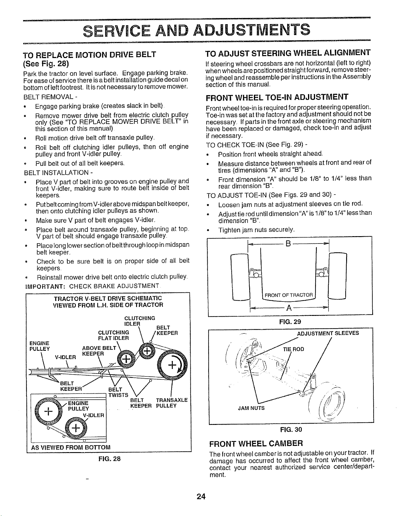
TO REPLACE MOTION DRIVE BELT
(See Fig. 28)
Park the tractor on level surface. Engage parking brake_
For ease of service there is a belt installation guide decal on
bottom of left footrest. It is not necessary to remove mower.
BELT REMOVAL -
• Engage parking brake (creates slack in belt).
- Remove mower drive belt from electric clutch pulley
only (See "TO REPLACE MOWER DRIVE BELT" in
this section of this manual)
• Roll motion drive belt off transaxle pulley_
, Roll belt off clutching idler pulleys, then off engine
pulley and front V-idler pulley.
o Pull belt out of all belt keeper&
BELT iNSTALLATION -
, Place V part of belt into grooves on engine pulley and
front V-idler, making sure to route belt inside of belt
keepers.
o Putbett coming from V-idler above midspan belt keeper,
then onto clutching idler pulleys as shown.
, Make sure V part of belt engages V-idler.
Place belt around transaxle pulley, beginning at top.
V part of belt should engage transaxle pulley.
• Place long lower section of belt through loop in midspan
belt keeper.
• Check to be sure belt is on proper side of all belt
keepers
= Reinstall mower drive belt onto eJectric clutch pulley
IMPORTANT: CHECK BRAKE ADJUSTMENT
TRACTOR V-BELT DRIVE SCHEMATIC
VIEWED FROM L.H, SIDE OF TRACTOR
ENGINE
PULLEY
CLUTCHING
IDLER
BELT
CLUTCHING t KEEPER
FLAT IDLER
V-IDLER
_GINE
PULLEY
V-IDLER
BELT
TWISTS
BELT TRANSAXLE
KEEPER PULLEY
AS VIEWED FROM BOTTOM
FIG. 28
TO ADJUST STEERING WHEEL ALIGNMENT
tf steering wheel crossbars are not horizontal (left to right)
when wheels are positioned straight forward, remove steer-
lng wheel and reassemble per instructions in the Assembly
section of this manual..
FRONT WHEEL TOE-IN ADJUSTMENT
Front wheel toe-in is required for proper' steering operation.,
Toe-in was set at the factory and adjustment should not be
necessary. If parts in the front axle or steering mechanism
have been replaced or damaged, check toe-in and adjust
if necessary.,
TO CHECK TOE-IN (See Fig. 29) -
- Position front wheels straight ahead,
• Measure distance between wheels at front and rear of
tires (dimensions "A" and "B")o
. Front dimension "A" should be 1/8" to 1/4" less than
rear' dimension "B"..
TO ADJUST TOE-IN (See Fig& 29 and 30) -
- Loosen jam nuts at adjustment sleeves on tie rod..
° Adjust tie rod until dimension"A" is 1/8" to 1/4" less than
dimension "B",
• Tighten jam nuts securely.
FIG. 29
,--- ADJUSTMENT SLEEVES
/
TIE ROD
L ¸
JAM NUTS
FIG, 30
FRONT WHEEL CAMBER
The front wheel camber is not adjustable on your tractor-If
damage has occurred to affect the front wheel camber,
contact your nearest authorized service center/depart-
ment.
24
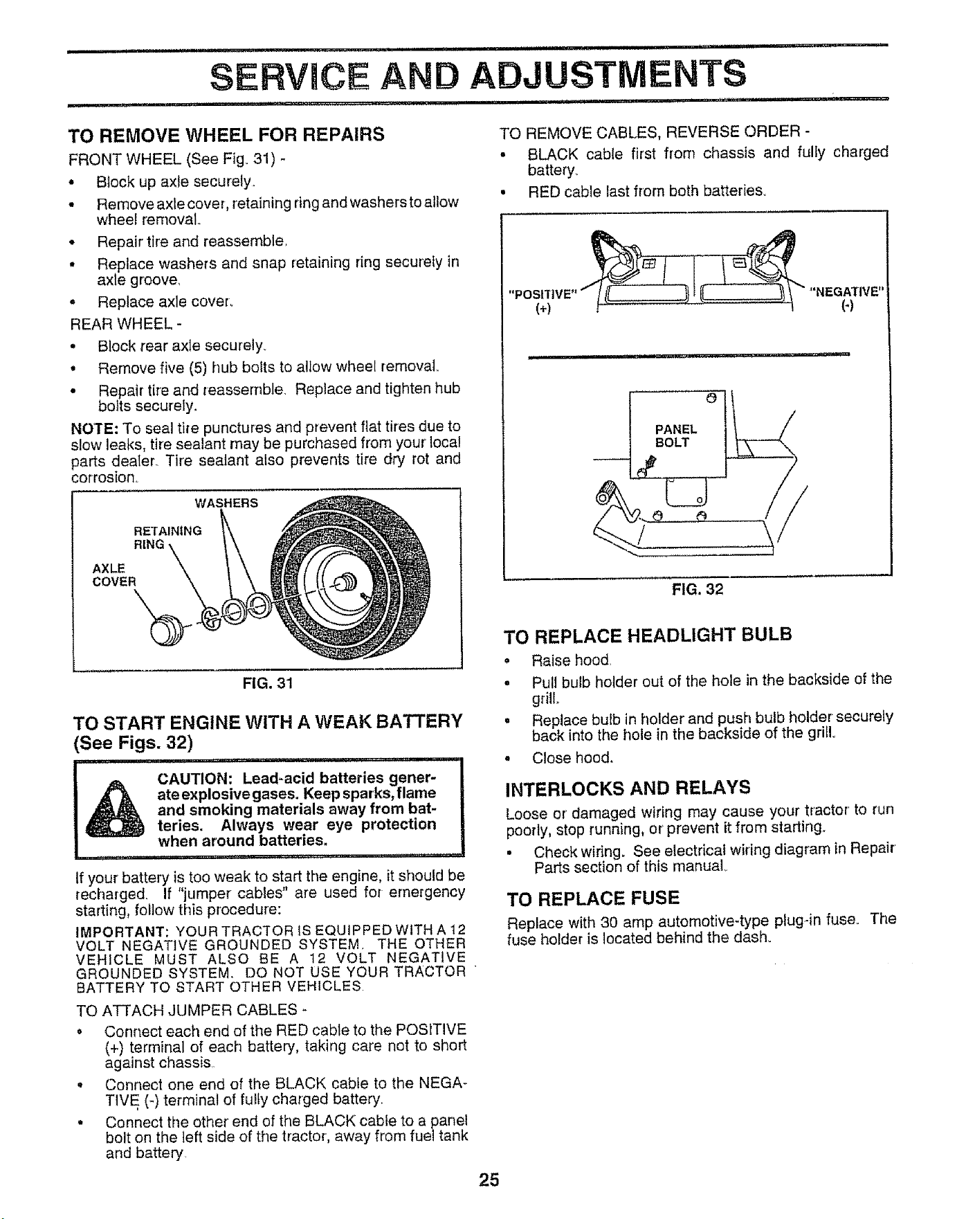
TO REMOVE WHEEL FOR REPAIRS
FRONT WHEEL (See Fig_ 31) -
* Block up axle securely,
° Remove axle cover, retaining ringand washers to allow
wheel removal.
. Repair' tire and reassemble,
° Replace washers and snap retaining ring securely in
axle g roove.
o Replace axle cover_
REAR WHEEL -
. Block rear axle securely
. Remove five (5) hub belts to allow wheel removal
• Repair tire and reassemble. Replace and tighten hub
bolts securely.
NOTE: To seal tire punctures and prevent flat tires due to
slow leaks, tire sealant may be purchased from your' local
parts dealer Tire sealant also prevents tire dry rot and
corrosion_
WASHERS
RETAINING
AXLE
COVER
FIG. 31
TO START ENGINE WITH A WEAK BATTERY
(See Figs. 32)
i , , , ii I, , 1,1,.,,11.11..,i. r
I& CAUTION: Lead-acid batteries gener-
ate explosive gases. Keep sparks, flame
and smoking materials away from bat-
teries. Always wear eye protection
when around batteries,
If your battery is too weak to start the engine, it should be
recharged. If "jumper' cables" are used for emergency
starting, follow this procedure:
IMPORTANT: YOUR TRACTOR IS EQUIPPED WiTH A 12
VOLT NEGATIVE GROUNDED SYSTEM, THE OTHER
VEHICLE MUST ALSO BE A 12 VOLT NEGATIVE
GROUNDED SYSTEM. DO NOT USE YOUR TRACTOR "
BATTERY TO START OTHER VEHICLES
TO ATTACH JUMPER CABLES -
• Connect each end of the RED cable to the POSITIVE
(+) terminal of each battery, taking care not to short
against chassis,
° Connect one end of the BLACK cable to the NEGA-
TIVE (-) terminal of fully charged battery.
• Connect the other end of the BLACK cable to a panel
bolt on the left side of the tractor, away from fuel tank
and battery,
TO REMOVE CABLES, REVERSE ORDER -
° BLACK cable first from chassis and fully charged
battery°
• RED cable last from both batteries.
O
PANEL
BOLT
o......\/
FIG. 32
TO REPLACE HEADLIGHT BULB
• Raise hood.
• Pull bulb holder out of the hole in the backside of the
grill,,
. Replace bulb in holder' and push bulb holder securely
back into the hole in the backside of the grill.
° Close hood.
INTERLOCKS AND RELAYS
Loose or damaged wiring may cause your tractor' to run
poorly, stop running, or prevent it from starting.
• Check wiring° See electrical wiring diagram in Repair
Parts section of this manual.
TO REPLACE FUSE
Replace with 30 amp automotive-type plug-in fuse. The
fuse holder is located behind the dash°
25
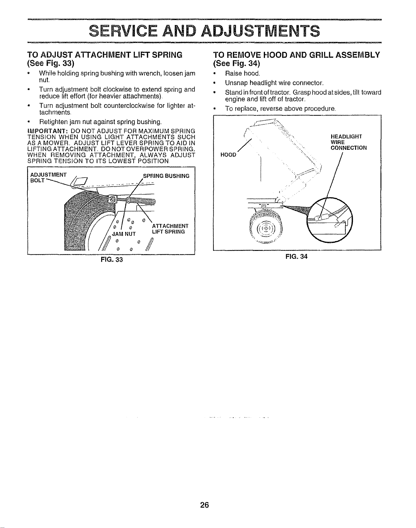
SERVICE AND ADJUSTMENTS
i i ................... lu,unl,, ,.... .... .......................i n lUnllUl
TO ADJUST ATTACHMENT LIFT SPRING
(See Fig, 33)
o While holding spring bushing with wrench, loosen jam
nuL
= Turn adjustment bolt clockwise to extend spring and
reduce lifteffort (for heavier' attachments)
• Turn adjustment bolt counterclockwise for lighter at-
tachments,
• Retighten jam nut against spring bushing_
IMPORTANT: DO NOT ADJUST FOR MAXIMUM SPRING
TENSION WHEN USING LIGHT ATTACHMENTS SUCH
AS A MOWER_ ADJUST LIFT LEVER SPRING TO AID IN
LIFTING ATTACHMENT. DO NOT OVERPOWER SPRING.
WHEN REMOVING ATTACHMENT, ALWAYS ADJUST
SPRING TENSION TO ITS LOWEST POSIT!ON
ADJUSTMENT SPRING BUSHING
BOLT
ATTACHMENT
JAM NUT LIFT SPRING
_ o
FIG. 33
TO REMOVE HOOD AND GRILL ASSEMBLY
(See Fig. 34)
- Raise hood,
• Unsnap headlight wire connector.
• Stand infront of tractor_ Grasp hood at sides, tilt toward
engine and lift off of tractor',,
- To replace, reverse above procedure,
HOOD
' :;_', HEADLIGHT
' WIRE
'" CONNECTION
7,
FIG. 34
26
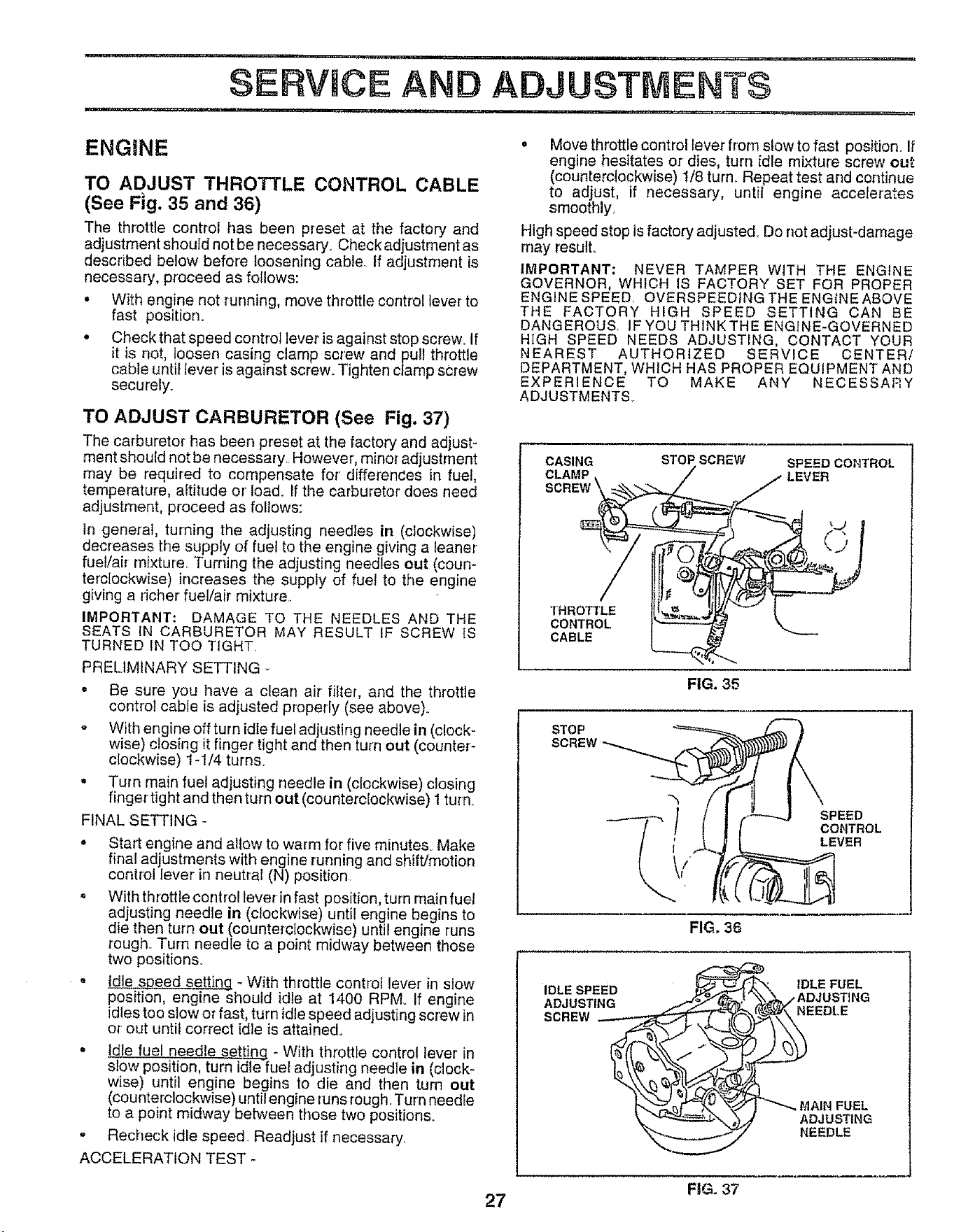
...... , ,,,,,,,, ,,,,
SERVICE A ADJUSTMENTS
ui,,Hi ,liH, i ....................... _ ........................ ,......... ,,-!
ENGINE
TO ADJUST THROTTLE CONTROL CABLE
(See Fig. 35 and 36)
The throttle control has been preset at tile factory and
adjustment should net be necessary Check adjustment as
described below before loosening cable If adjustment is
necessary, proceed as follows:
• With engine not running, move throttle control lever to
fast position.
• Check that speed control lever is against stop screw. If
it is not, loosen casing clamp screw and pul! throttle
cable until lever is against screw.. Tighten clamp screw
securely.
TO ADJUST CARBURETOR (See Fig. 37)
The carburetor has been preset at tile factory and adjust-
ment should not be necessary However, minor adjustment
may be required to compensate for differences in fuel,
temperature, altitude or load. If the carburetor does need
adjustment, proceed as follows:
in gene_'al, turning the adjusting needles in (clockwise)
decreases the supply of fuel to the engine giving a leaner
fuel/air mixture. Turning the adjusting needles out (coun-
terclockwise) increases the supply of fuel to the engine
giving a richer fuel/air mixture
IMPORTANT: DAMAGE TO THE NEEDLES AND THE
SEATS iN CARBURETOR MAY RESULT IF SCREW tS
TURNED IN TOO TIGHT
PRELIMINARY SETTING
o Be sure you have a clean air filter, and the throttle
control cable is adjusted properly (see above)
,, With engine off turn idle fuel adjusting needle in (clock-
wise) closing it finger tight and then turn out (counter-
clockwise) 1-1/4 turns.
• Turn main fuel adjusting needle in (clockwise) closing
finger tight and then turn out (counterclockwise) 1 turn
FINAL SETTING -
• Start engine and allow to warm for five minutes° Make
final adjustments with engine running and shift/motion
control lever in neutral (N) position
o With throttle controltever in fast position, turn main fue!
adjusting needle in (clockwise) until engine begins to
die then turn out (counterclockwise) until engine runs
rough Turn needle to a point midway between those
two positions.
Idle speed setting - With throttle control lever in slow
position, engine should idle at 1400 RPMo If engine
idles too slow or fast, turn idle speed adjusting screw in
or out until correct idle is attained.
• Idle fuel needle setting - With throttle control lever in
slow position, turn idle fuel adjusting needle in (clock-
wise) until engine begins to die and then turn out
(counterclockwise) until engine runs rough. Turn needle
to a point midway between those two positions.
- Recheck idle speed Readjust if necessary
ACCELERATION TEST -
, Move throttle control lever from slow to fast position. If
engine hesitates or dies, turn idle mixture screw ou_:
(counterclockwise) 1/8 turn. Repeat test and continue
to adjust, if necessary, untit engine accelerates
smoothly,
High speed stop is factory adjusted_ Do not adjust-damage
may result.
IMPORTANT: NEVER TAMPER WITH THE ENGINE
GOVERNOR, WHICH tS FACTORY SET FOR PROPER
ENGINE SPEED. OVERSPEEDING THE ENGINE ABOVE
THE FACTORY HIGH SPEED SETTING CAN BE
DANGEROUS IF YOU THINK THE ENGINE-GOVERNED
HIGH SPEED NEEDS ADJUSTING, CONTACT YOUR
NEAREST AUTHORIZED SERVICE CENTER!
DEPARTMENT, WHICH HAS PROPER EQUIPMENT AND
EXPERIENCE TO MAKE ANY NECESSARY
ADJUSTMENTS.
CASING STOP SCREW SPEED CONTROL
CLAMP LEVER
THROTTLE
CONTROL
CABLE
FIG. 35
STOP
SPEED
CONTROL
LEVER
FIG. 36
IDLE SPEED
ADJUSTING
SCREW
IDLE FUEL
_EEDLE
MAIN FUEL
ADJUSTING
NEEDLE
FIG. 37
27
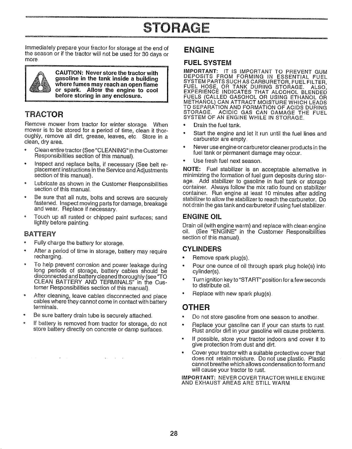
......... ' i ......... ,,,urn,=,, IH,, ,i,,,=,= , =,u ,, ,n ......... .-- L............ ,
STORAGE
: _ ,_ ii= ,u ,,,,H ..... ,,.,,r_ nil H ,_ --
Immediately prepare your tractor for storage at the end of ENGINE
the season or if the tractor will not be used for' 30 days or'
more
CAUTION: Never store the tractor with
gasoline in the tank inside a building
where fumes may reach an open flame
or spark. Allow the engine to cool
before storing in any enclosure.
TRACTOR
Remove mower from tractor for winter' storage. When
mower is to be stored for a period of time, clean it thor-
oughly, remove all dirt, grease, leaves, etc Store in a
clean, dry area,.
. Clean entire tractor (See"CLEANtNG" in the Customer
Responsibilities section of this manual).
• Inspect and replace belts, if necessary (See belt re-
placement instructions in the Service and Adjustments
section of this manual).
o Lubricate as shown in the Customer Responsibilities
section of this manual,
o Be sure that at1 nuts, bolts and screws are securely
fastened,. Inspect moving parts for damage, breakage
and wear_ Replace if necessary
o Touch up all rusted or chipped paint surfaces; sand
lightly before painting
BATTERY
Fully charge the battery for storage°
- After a period of time in storage, battery may require
recharging°
o To help prevent corrosion and power leakage during
long periods of storage, battery cables should be
disconnected and battery cleaned thoroughly (see"TO
CLEAN BATTERY AND TERMINALS" in the Cus-
tomer Responsibilities section of this manual).
After cleaning, leave cables disconnected and place
cables where they cannot come in contact with battery
terminals.
= Be sure battery drain tube is securely attached,,
o If battery is removed from tractor for storage, do not
store battery directly on concrete or damp surfaces,,
FUEL SYSTEM
IMPORTANT: IT tS IMPORTANT TO PREVENT GUM
DEPOSITS FROM FORMING iN ESSENTIAL FUEL
SYSTEM PARTS SUCH AS CARBURETOR, FUEL FILTER,
FUEL HOSE, OR TANK DURING STORAGE. ALSO,
EXPERIENCE iNDICATES THAT ALCOHOL BLENDED
FUELS (CALLED GASOHOL OR USING ETHANOL OR
METHANOL) CAN ATTRACT MOISTURE WHICH LEADS
TO SEPARATION AND FORMATION OF ACIDS DURING
STORAGE, ACIDIC GAS CAN DAMAGE THE FUEL
SYSTEM OF AN ENGINE WHILE iN STORAGE.
" Drain the fuel tank.
. Start the engine and let it run until the fuel lines and
carburetor are empty,
= Never' use engine or carburetor cleaner products in the
fuel tank or permanent damage may occur.
= Use fresh fuel next season,,
NOTE; Fuel stabilizer is an acceptable alternative in
minimizing the formation of fuel gum deposits during stor'-
age. Add stabilizer to gasoline in fuel tank or storage
container, Always follow the mix ratio found on stabilizer
container'. Run engine at least 10 minutes after adding
stabilizer to allow the stabilizer' to reach the carburetor'. Do
not drain the gas tank and carburetor if using fuel stabilizer'
ENGINE OIL
Drain oil (with engine warm) and repface with clean engine
oilo (See "ENGINE" in the Customer Responsibilities
section of this manual),
CYLINDERS
• Remove spark plug(s)_
• Pour one ounce of oil through spark plug hole(s) into
cylinder(s).
° Turn ignition key to"START" position for a few seconds
to distribute oil
. Replace with new spark plug(s)
OTHER
. Do not store gasoline from one season to another,,
. Replace your gasoline can if your can starts to rust
Rust and/or dirt in your gasoline will cause preblems_
- If possible, store your tractor indoors and cover it to
give protection from dust and dirt,
° Cover your tractor with a suitable protective cover that
does not retain moisture. Do not use plastic. Plastic
cannot breathe which allows condensation to form and
will cause your tractor to rust.
IMPORTANT: NEVER COVER TRACTOR WHILE ENGINE
AND EXHAUST AREAS ARE STILL WARM
28
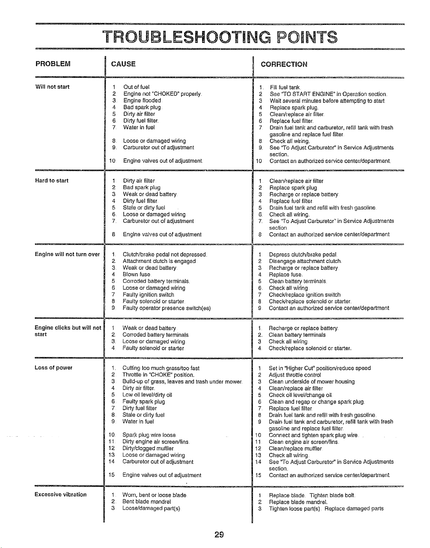
'=H...... ,, ,,, ,, ,, ,, ,
TROUBLESHOOTING POINTS
.......... ...... ,,,, ,,,,,, ,,,,,,, ,,,, ....... ,
PROBLEM CAUSE CORRECTION
Will not start
Hard to start
Engine wilt not turn over
1 Out of fuel
2 Engine not "CHOKED" properly
3 Engine flooded
4 Bad spark plug
5 Dirty air filter
6 Dirty fuel fitter
7 Water in fuel
8 Loose or damaged wiring
9 Carburetor out of adjustment
10 Engine valves out of adjustment
1 Fill fuel tank,
2 See "TO START ENGINE" in Operation section,
3 Wait several minutes before attempting to start
4 Replace spark plug.
5 Clean/replace air fitter
6 Replace fuel filter
7 Drain fuel tank and carburetor, refill tank with fresh
gasoline and replace fuel filter,
8 Check all wiring.
9, See "To Adjust Carburetor _in Service Adjustments
section.
10 Contact an authorized service center/department
Engine clicks but wi!l not
start
1 Dirtyair !liter
2 Bad spark plug
3 Weak or dead battery
4 Dirty fuel filter
5 Stale or dirty fuel
6. Loose or damaged wiring
7_ Carburetor out of adjustment
8 Engine valves out of adjustment
1 Clean/replace air filter
2 Replace spark plug
3 Recharge or replace battery
4 Reptace !uel filter
5 Drain fuel tank and refiil with fresh gasoline
6 Check all wiring.
7, See "To Adjust Carburetor" in Service Adjustments
section
8 Contactan authorized service center/department
re.r,
Loss of power
1 Cfutch/brake pedal not depressed
2 Attachment dutch is engaged
3 Weak or dead battery
4 B_own fuse
5 Corroded battery terminals,
6 Loose or damaged wiring
7 Faulty ignition switch
8 Faulty solenoid or starter
9 Faulty operator presence switch(as)
! Depress c{utch,,'brake pedal
2 Disengage attachment clutch
3 Recharge or replace battery
4 Replace fuse_
5 Clean battery terminals
6. Check all wiring
7 Check/replace ignition switch
8 Check/replace solenoid or starter,
9 Contact an authorized sen'ice centerldepartrnent
Excessive vibration
1 Weak or dead battery
2, Corroded battery terminals
3, Loose or damaged wiring
4 Faulty solenoid or starter
1, Cutting too much grass/too fast
2 Throttle in "CHOKE" position.
3 Build-up of grass, leaves and trash under mower
t Recharge or replace battery
2, Clean battery terminals
3 Checkatfwidng
4 Check/replace solenoid or starter,
1 Set in "Higher Cut" posifion/reduce speed
2 Adjust throttle control
3 Clean underside of mower housing
4 Dirty air filter_
5 Low oil level/dirty oil
6 Faulty spark plug
7 Dirty fuel fiiter
8 Stale or dirty fuel
9 Water in fuel
10 Spa,tk ptugwire loose
11 Dirty engine air screen/fins
12 Dirty!clogged muffler
13 Loose or damaged wiring
4 Clean/replace air filter
5 Check oil levef/change oil
6 Clean and regap or change spark plug.
7 Replace fuel filter
8 Drain fuel tank and refili with fresh gasoline
9 Drain fuel tank and carburetor, refill tank with fresh
gasoline and replace fuel filter
10 Connectand tighten spark plug wire.
1 t Clean engine air screen/fins
12 Clean/replace muffler
13 Check atl wiring.
14 Carburetor out of adjustment
15 Engine valves out of adjustment
i,, ,,-, , ,,
t Worn, bent or loose blade
2 Bent blade mandrel
3 Loose/damaged part(s)
14 See "To Adjust Carburetor" in Service Adjustmerits
section,
15 Contact an authorized service center/depadment
1 Replace blade Tighten blade bolt,
2 Replace blade mandrel.
3 Tighten loose part(s) Replace damaged parts
29
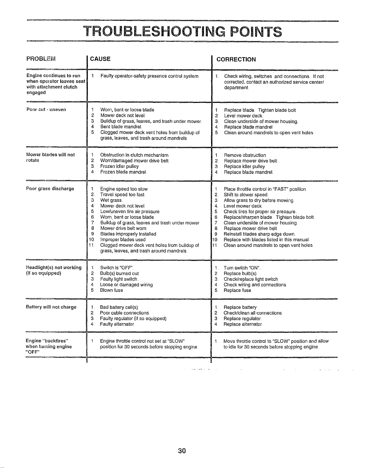
_-_ .................. , ,, i,i i,iii i,,, ,...... , ,,,_.,,_,_,,ii, ILI"I"IL
TROUBLESHOOTING POINTS
PROBLEIVJ
Engine continues to run
when operator leaves seat
with attachment clutch
engaged
Poor" cut _ uneven
Mowsr blades wilt not
rotate
Poor grass discharge
Headlight(s) not working
(if so equipped)
Battery will not charge
Engine "backfires"
when turning engine
"OFF"
CAUSE
=,,,!
1 Faulty operator-safety presence control system
,11111111 ....................
1 Worn, bent or Ioose blade
2 Mower deck not level
3 Buildup of grass, leaves, and trash unde_ mower.
4 Bent biade mandrel
5 Clogged mower deck vent holes from buildup of
grass, leaves, and trash around mandrels
............... ii,, ,.... , ill
1 Obstruction in clutch mechanism
2 Worn/damaged mower drive belt
3 Frozen idler pu!ley
4 Frozen blade mandrel
CORRECTION
, = =lIHHHI
1 Cheek wiring, switches andconnecf{ons. If not
corrected, contact an authorized service center/
department
1 Replace blade Tighten blade bolt
2 Level mower deck.
3 Clean underside of mower housing
4 Replace blade mandrel
5 Clean around mandrels to open vent holes
,,, i1,11 ii
1 Remove obstruction
2 Replace mower drive belt
3 Replace idler pultey
4 Replace blade mandrel
1 Engine speed too slow
2 TraveI speed too fast.
3 Wet grass
4 Mower deck not levei
5 Low/uneven tire air pressure
6 Worn. bent orloose biade
7 Buildup of grass, leaves and trash under mower
8 Mower drive belt worn
9 B_ades improperly installed
!0 improper blades used
I Clogged mower deck vent holes from buildup of
grass, leaves, and trash around mandrels
1 Place throttle control in "FAST" position
2 Shift to slower speed.
3 Allow grass to dry before mowing
4. Level mower deck
5 Checktires for proper air pressure.
6 Replace/sharpen blade Tighten blade bolt
7 Clean underside of mower housing
8 Replace mower drive belt
9 Reinstall blades sharp edge down
10 Replace with blades listed in this manual
11 Clean around mandrels to open vent hotes
t Switch is "OFF"
2 Bulb(s) burned out
3 Faulty light switch
4 Loose or damaged wiring
5 Blown fuse
1 Turn switch "ON".
2 Replace bulb(s)
3 Check/replace _ight switch
4 Check wiring and connections
5 Replace fuse
1 Bad battery ceil(s)
2 Poor cableconnections
3 Faulty regulator (if so equipped)
4 Fauity alternator
1 Engine throttle control not set at "SLOW"
position for 30 seconds before stopping engine
1 Replace battery
2 Check/clean all connections
3 Replace regulator
4 Replace alternator
! Move throttle control to "SLOW" posifion and allow
to idIe for 30 seconds before stopping engine
3O
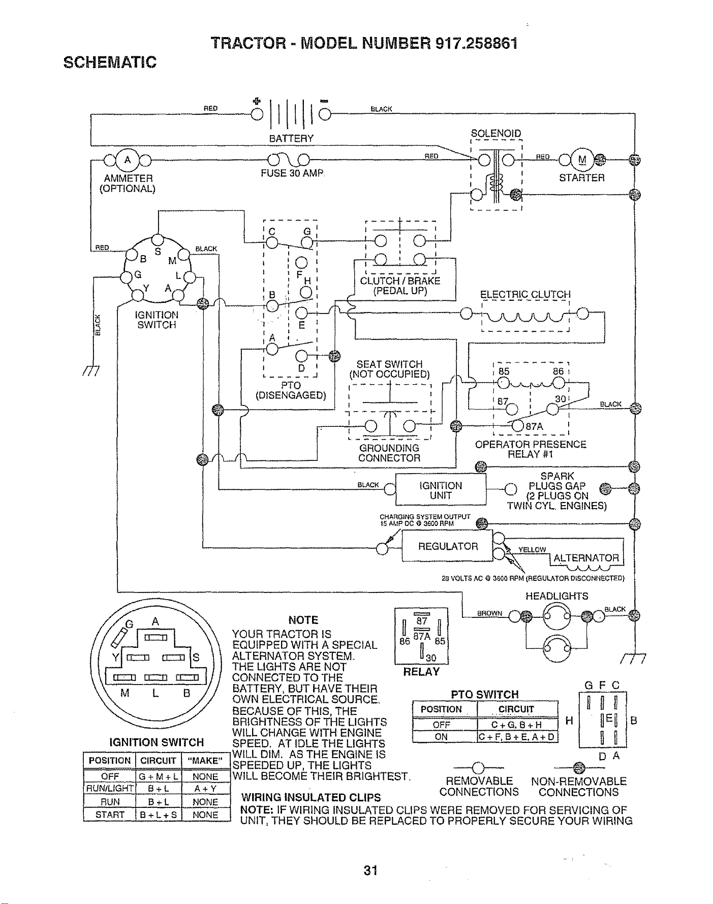
SCHEMATIC
TRACTOR - MODEL NUMBER 917.258861
[
AMMETER
(OPTIONAL)
°ILL
BATTERY
FUSE30 AMP.
j I I
' :© f
I _ H I
B
1 ,' L k.J_
', :E:
IA ',
_ D _
L ..... _
PTO
(DISENGAGED)
I O ,
CLUTCH/ BRAKE
(PEDAL UP)
SEAT SWITCH
(NOT OCCUPIED)
k
T
L .........
GROUNDING
CONNECTOR
SOLENOID
[__ STARTER
ELECTRIC CLUTCH
BLACF,
)87A
OPERATOR PRESENCE
RELAY #1
®
4_ ] SPARK
B_CK IGNITION _-4_3 PLUGS GAP
UNIT 1 _-" (2 PLUGS ON "_
TWIN CYL ENGINES) i
CHARGING SYSTEM OUTPUT
15 A},_P DC O 36(_ORPM
REGULATOR _ YELLOW
28 VOLTS AC @ 3_00 NPM (REGULATOR DISCONN_CTEDt
IGNITION SWITCH
POSITION _ "MAKE"
OFF G + M + L NONE
RuNiLiGHT B + L A + Y
RUN B ÷ L NONE
START IB+L+S NONE
i
NOTE
YOUR TRACTOR IS
EQUIPPED WITH A SPECIAL
ALTERNATOR SYSTEM
THE LIGHTS ARE NOT
CONNECTED TO THE
BATTERY, BUT HAVE THEIR
OWN ELECTRICAL SOURCE..
BECAUSE OF THIS, THE
BRIGHTNESS OF THE LIGHTS
WILL CHANGE WITH ENGINE
SPEED. AT IDLE THE LIGHTS
WILL DIM. AS THE ENGINE IS
SPEEDED UP, THE LIGHTS
WILL BECOME THEIR BRIGHTEST.
WIRING INSULATED CLIPS
RELAY
HEADLIGHTS
f_ROWN
\-_11 /%
PTO SWITCH
POSITION CIRCUIT
OFF C+G,B+H
ON C+F,B+E,A+D
O
REMOVABLE
CONNECTIONS
GFC
H B
un
DA
@
NON-REMOVABLE
CONNECTIONS
NOTE: IF WIRING INSULATED CLIPS WERE REMOVED FOR SERVICING OF
UNIT, THEY SHOULD BE REPLACED TO PROPERLY SECURE YOUR WIRING
31
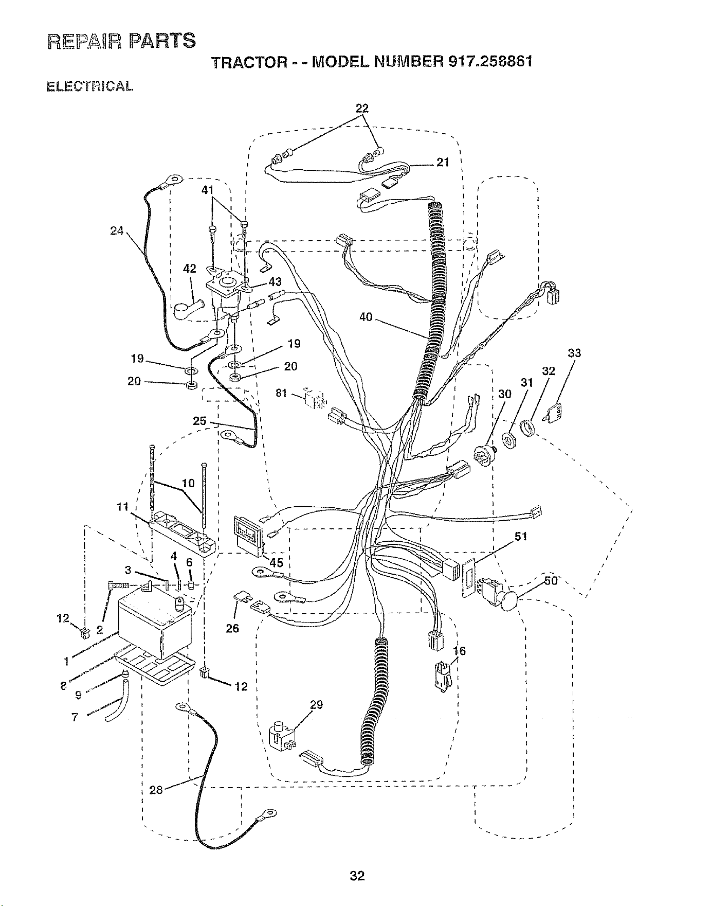
REPAIR PARTS
TRACTOR - -MODEL NUMBER 917.258861
ELECT$_CAL
22
i
i
i
i
I
2 !
24
31
51
i
i 26
12
\
1_6
29 :
33
32
32
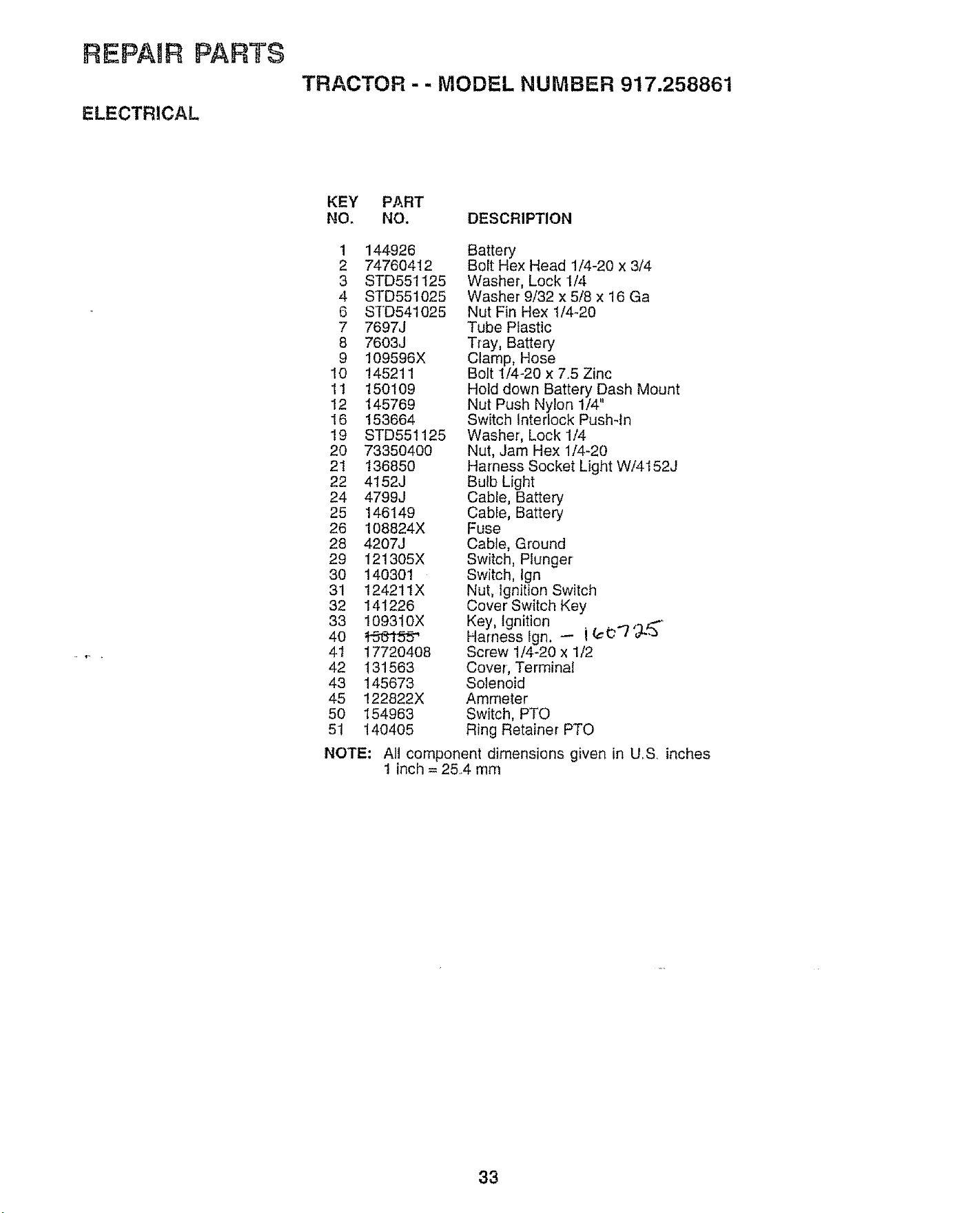
REPAAR PARTS
TRACTOR -- MODEL NUMBER 917.258861
KEY PART
NO, NO. DESCRIPTION
1 144926
2 74760412
3 STD551125
4 STD551025
6 STD541025
7 7697J
8 7603J
9 109596X
10 145211
11 150109
12 145769
16 153664
19 STD551125
20 73350400
21 136850
22 4152J
24 4799J
25 146149
26 108824X
28 4207J
29 121305X
30 140301
31 124211X
32 141226
33 109310X
40 _J6"tS_
41 17720408
42 131563
43 145673
45 !22822X
50 154963
51 140405
NOTE:
Battery
Bolt Hex Head 1/4_20 x 3/4
Washer, Lock 1/4
Washer 9/32 x 5/8 x 16 Ga
Nut Fin Hex 1/4-20
Tube Plastic
Tray, Battery
Clamp, Hose
Bolt 1/4-20 x 7.5 Zinc
Hold down Battery Dash Mount
Nut Push Nylon 1/4"
Switch Interlock Pushqn
Washer, Lock 1/4
Nut, Jam Hex 1/4-20
Harness Socket Light W/4152J
Bulb Light
Cable, Battery
Cable, Battery
Fuse
Cable, Ground
Switch, Plunger
Switch, Ign
Nut, Ignition Switch
Cover Switch Key
Key, Ignition
Harness Ign. -- i (¢_"7 '3-_"
Screw 1/4-20 x 1/2
Cover, Terminal
Solenoid
Ammeter
Switch, PTO
Ring Retainer PTO
AIt component dimensions given in U_S inches
1 inch = 254 mm
33
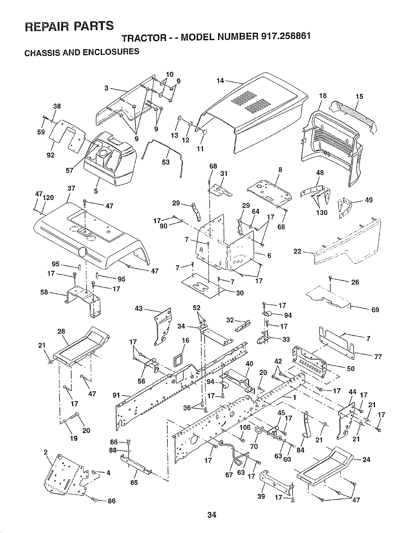
REPAIR PARTS
TRACTOR -- MODEL NUMBER 917.258861
CHASSIS AND ENCLOSURES
59
38
92
57
53
47120 37 5
_47
I
47
17
91
47
56
19
2O
86
11
68
l
17
18 15
/
67
8 48
64 _
17 / 130
68
49
t7
42
77
34
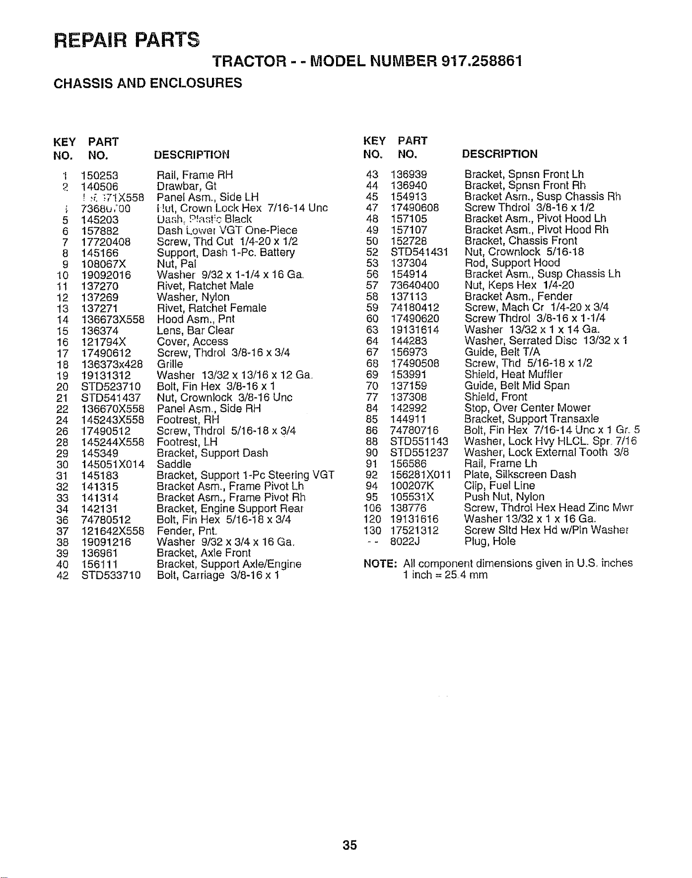
REPAIR PARTS
TRACTOR - - MODEL NUMBER 917.258861
CHASSIS AND ENCLOSURES
KEY PART KEY PART
NO. NO. DESCRIPTION NOu NO.
1 150253 Rail, Frarne RH 43 136939
.P. 140506 Drawbar, Gt 44 136940
! ;_. _7tX558 PanefAsm. Side LH 45 154913
7368L_/00 t!ut, Crown Lock Hex 7/16-14 Unc 47 17490608
5 145203 IJasl_ ._!_st:c Black 48 157105
6 157882 Dash Lower VGTOne-Piece 49 157107
7 17720408 Screw, Thd Cut 1/4-20 x 1/2 50 152728
8 145166 Support, Dash 1-Pc. Battery 52 STD541431
9 108067X Nut, Pal 53 137304
10 19092016 Washer 9/32 x 1-1/4 x 16 Ga. 56 154914
11 137270 Rivet, Ratchet Male 57 73640400
12 137269 Washer, Nylon 58 137113
13 137271 Rivet, Ratchet Female 59 74180412
14 136673X558 Hood Asm. Pnt 60 17490620
15 136374 Lens, Bar'Clear 63 19131614
16 121794X Cover, Access 64 144283
17 17490612 Screw, Thdrol 3/8-16 x3/4 67 156973
18 136373x428 Grille 68 17490508
19 19131312 Washer 13/32 x 13/16 x 12 Ga. 69 153991
20 STD5237t0 Bolt, Fin Hex 3/8-16 x I 70 137159
21 STD541437 Nut, Crowniock 3/8-16 Unc 77 I37308
22 136670X558 Panel Asmo, Side RH 84 I42992
24 145243X558 Footrest, RH 85 144911
26 17490512 Screw, Thdrol 5/16-18 x 3/4 86 74780716
28 145244X558 Footrest, LH 88 STD551143
29 145349 Bracket, Support Dash 90 STD551237
30 145051X014 Saddle 91 156586
31 145183 Bracket, Support l-Pc Steering VGT 92 156281X011
32 141315 Bracket Asm., Frame Pivot Lh 94 100207K
33 141314 Bracket Asm., Frame Pivot Rh 95 105531X
34 142131 Bracket, Engine Support Rear 106 138776
36 74780512 Bolt, Fin Hex 5/16-18 x 3/4 120 19131616
37 121642X558 Fender, Pnt. 130 17521312
38 19091216 Washer 9/32 x 3/4 x 16 Ga. -- 8022J
39 136961 Bracket, Axle Front
40 156111 Bracket, Support Axle/Engine
42 STD533710 Bolt, Carriage 3/8-16 x 1
DESCRIPTION
Bracket, Spnsn Front Lh
Bracket, Spnsn Front Rh
Bracket Asrn., Susp Chassis Rh
Screw Thdrol 3/8-16 x 1/2
Bracket Asm. Pivot Hood Lh
Bracket Asm. Pivot Hood Rh
Bracket, Chassis Front
Nut, Crownlock 5/16-18
Rod, Support Hood
Bracket Asmo, Susp Chassis Lh
Nut, Keps Hex 1/4-20
Bracket Asmo, Fender
Screw, Mach Cr 1/4-20 x 3/4
ScrewThdrol 3/8-16 x 1-1/4
Washer 13/32 x 1 x 14Gao
Washer, Serrated Disc 13/32 x 1
Guide, Belt T/A
Screw, Thd 5/16-18 x 1/2
Shield, Heat Muffler'
Guide, Belt Mid Span
Shield, Front
Stop, Over Center Mower
Bracket, Support Transaxle
Bolt, Fin Hex 7/16-14 Uric x I Gr..5
Washer, Lock Hvy HLCL Spr. 7/16
Washer', Lock External Tooth 3/8
Rail, Frame Lh
Plate, Silkscreen Dash
Clip, Fuel Line
Push Nut, Nylon
Screw, Thdrol Hex Head Zinc Mwr
Washer 13/32 x 1 x 16 Ga..
Screw Sltd Hex Hd w/Ptn Washer
Plug, Hole
NOTE: Ail component dimensions given in U.S.. inches
1 inch = 25.4 mm
35
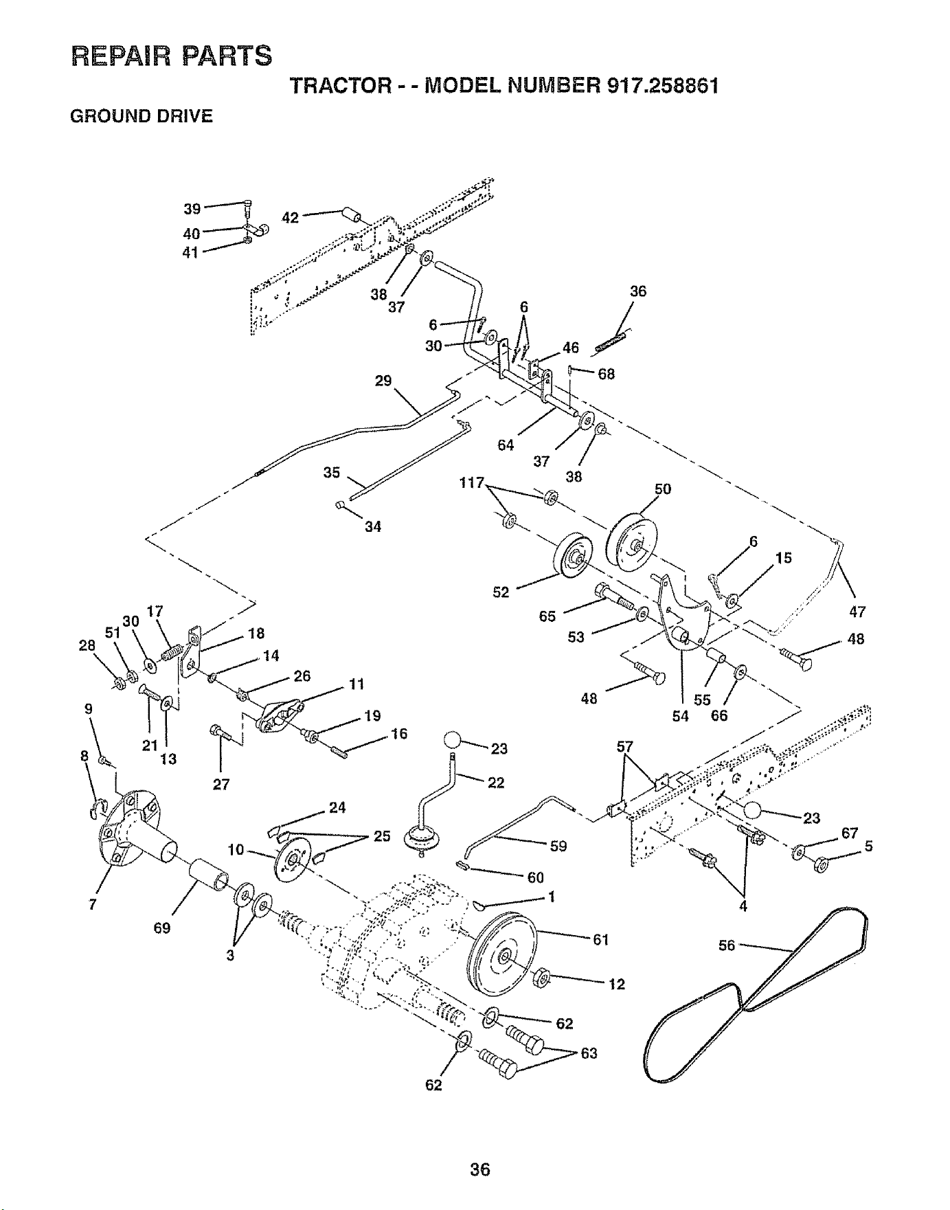
REPAIR PARTS
GROUND DRIVE
TRACTOR -- MODEL NUMBER 917.258861
= _" 38 36
i', 37 6
12
23
67
62
36
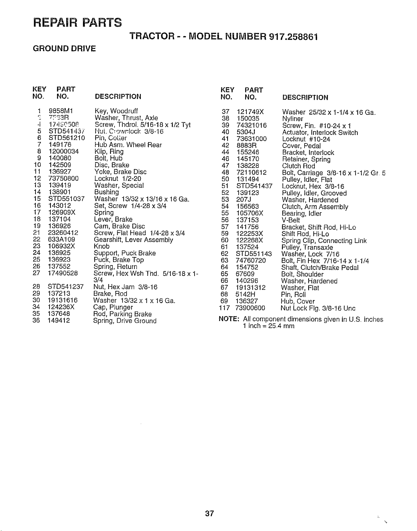
REPAIR PARTS
GROUND DRIVE
TRACTOR- - MODEL NUMBER 917.258861
KEY PART
NO, NO.
1 9858M1
'_ 7F_3R
,i 17,t_508
5 8TD54143/
6 STD561210
7 149176
8 12000034
9 140080
10 142509
11 136927
12 73750800
13 139419
14 138901
15 STD551037
16 143012
17 126909X
18 137104
19 136926
21 23260412
22 633A109
23 106932X
24 136925
25 136923
26 137552
27 17490528
28 STD541237
29 137213
30 19131616
34 124236X
35 137648
36 149412
DESCRIPTION
Key, Woodruff
Washer, Thrust, Axle
Screw, Thdrot. 5/16.-18 x 1/2 Tyt
NuL C:owr.lock 3/8-16
Pin, Cot[er
Hub Asm. Wheel Rear
Klip, Ring
Bolt, Hub
Disc, Brake
Yoke, Brake Disc
Locknut 1/2-20
Washer, Special
Bushing
Washer 13/32 x 13/16 x 16 Ga.
Set, Screw 1/4-28 x 3/4
Spring
Lever, Brake
Cam, Brake Disc
Screw, Fiat Head !/4-28 x 3/4
Gearshift, Lever Assembly
Knob
Support, Puck Brake
Puck, Brake Top
Spring, Return
Screw, Hex Wsh Thd_ 5/16-18 x 1-
3/4
Nut, Hex Jam 3/8-16
Brake, Rod
Washer' 13/32 x I x 16 Ga,,
Cap, Plunger
Rod, Parking Brake
Spring, Drive Ground
KEY PART
NO. NO, DESCRIPTION
37 121749X
38 150035
39 74321016
40 5304J
41 736310OO
42 8883R
44 155246
46 145170
47 138228
48 72110612
50 131494
51 STD54t437
52 139123
53 207J
54 156563
55 105706X
56 137153
57 141756
59 122253X
60 122268X
6t 137524
62 STD551143
63 74760720
64 154752
65 67609
66 140296
67 19131312
68 5142H
69 136327
117 73900600
Washer 25/32 x 1-1/4 x 16 Ga.
Nyliner
Screw, Fin. #10-24 x 1
Actuator, Interlock Switch
Locknut #!0-24
Cover, Pedal
Bracket, Interlock
Retainer, Spring
Clutch Rod
Bolt, Carriage 3/8-16 x 1-1/2 Gr. 5
Pulley, Idler, Flat
Locknut, Hex 3/8-16
Pulley, Idler, Grooved
Washer, Hardened
Clutch, Arm Assembly
Bearing, Idler
V-Belt
Bracket, Shift Rod, Hi-Lo
Shift Rod, Hi-Lo
Spring Clip, Connecting Link
Pulley, Transaxle
Washer, Lock 7/16
Bolt, Fin Hex 7/16-14 x 1-1/4
Shaft, Clutch/Brake Pedal
Bolt, Shoulder
Washer, Hardened
Washer, Fiat
Pin, Roll
Hub, Cover
Nut Lock Fig, 3/8-16 Unc
NOTE: All component dimensions given in U.S. inches
t inch = 25.4 mm
37 _,
%
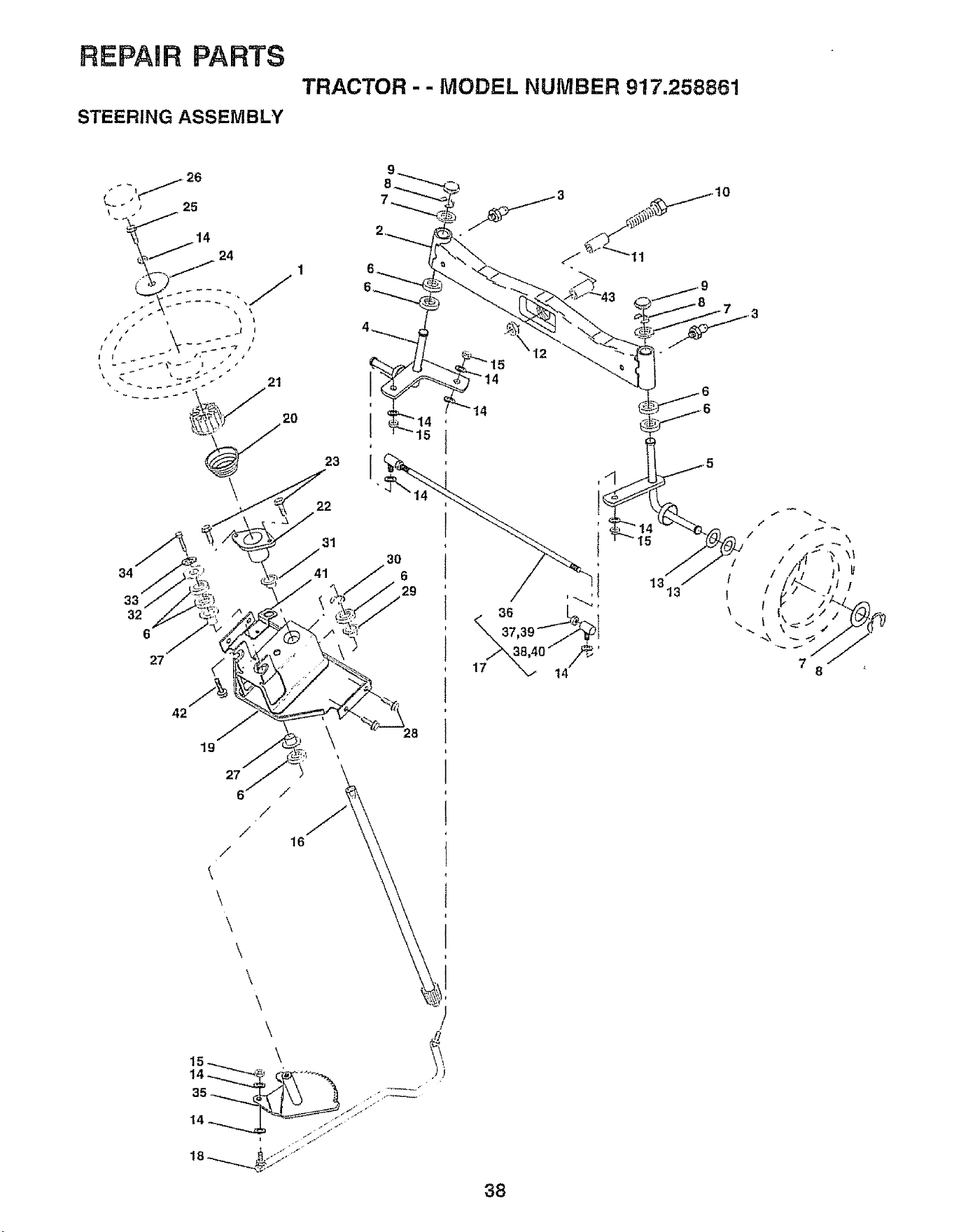
REPAIR PARTS
STEERING ASSEMBLY
TRACTOR - - MODEL NUMBER 917.258861
34
33
32
6
27
19
27
6 /
/
/
/
\
\
\
\
\
\
\
16
23
22
31
15
2B
/}
14
1313
/
!
I
\
14
38
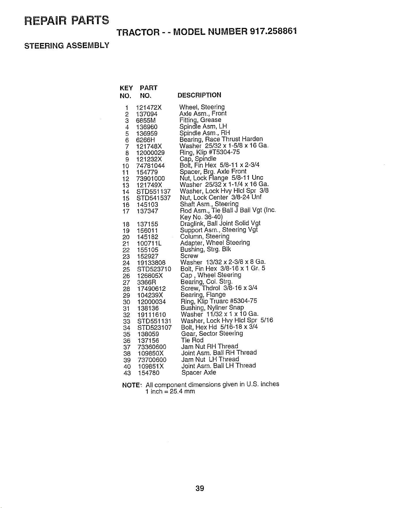
REPAIR PARTS
STEERING ASSEMBLY
TRACTOR -- MODEL NUMBER 917.258861
KEY PART
NO. NO. DESCRIPTION
t 121472X
2 137094
3 6855M
4 136960
5 136959
6 6266H
7 121748X
8 12000029
9 121232X
10 74781044
11 154779
12 73901000
13 t21749X
14 STD551137
15 STD541537
18 145103
17 137347
18 137155
19 156011
20 145182
21 100711L
22 155105
23 152927
24 19133808
25 STD523710
26 126805X
27 3366R
28 17490612
29 104239X
30 12O00O34
31 138138
32 19111610
33 STD551131
34 STD523107
35 138059
36 137156
37 73360600
38 109850X
39 73700600
40 109651X
43 154780
Wheel, Steering
Axle Asm. Front
Fitting, Grease
Spindle Asm, LH
Spindle Asm., RH
Bearing, Race Thrust Harden
Washer 25/32 x 1-5/8 x !6 Ga..
Ring, Kiip #'1"5304-75
Cap, Spindle
Bolt, Fin Hex 5/8-1 t x 2-3/4
Spacer, B_g. Axle Front
Nut, Lock Flange 5/8-11 Unc
Washer 25/32 x 1-1/4 x 16 Ga.
Washer, Lock Hvy Hlcl Spr 3/8
Nut, Lock Center' 3/8-24 Unf
Shaft Asm. Steering
Rod Asm,, Tie Ball J Bail Vgt (Inc.
Key No. 36-40)
Draglink, BaH Joint Solid Vgt
Support Asm. Steering Vgt
Column, Steering
Adapter, Wheel Steering
Bushing, Strg_ B]k
Screw
Washer' 13/32 x 2-3/8 x 8 Ga.
Bolt, Fin Hex 3/8q6 x I Gr. 5
Cap, Wheel Steering
Bearing, CoL Strg_
Screw, Thdrol 3/8-16 x 3/4
Bearing, Flange
Ring, Klip Truarc #5304-75
Bushing, Nyliner Snap
Washer 11/32 x 1 x 10 Ga..
Washer', Lock Hvy Hlcl Spr 5/16
Bolt, Hex Hd 5/16q8 x 3/4
Gear', Sector Steering
Tie Rod
Jam Nut RH Thread
Joint Asm. Ball RH Thread
Jam Nut LH Thread
Joint Asm. BaLI LH Thread
Spacer Axle
NOTE'. All component dimensions given in U.S. inches
1 inch = 2&4 mm
39
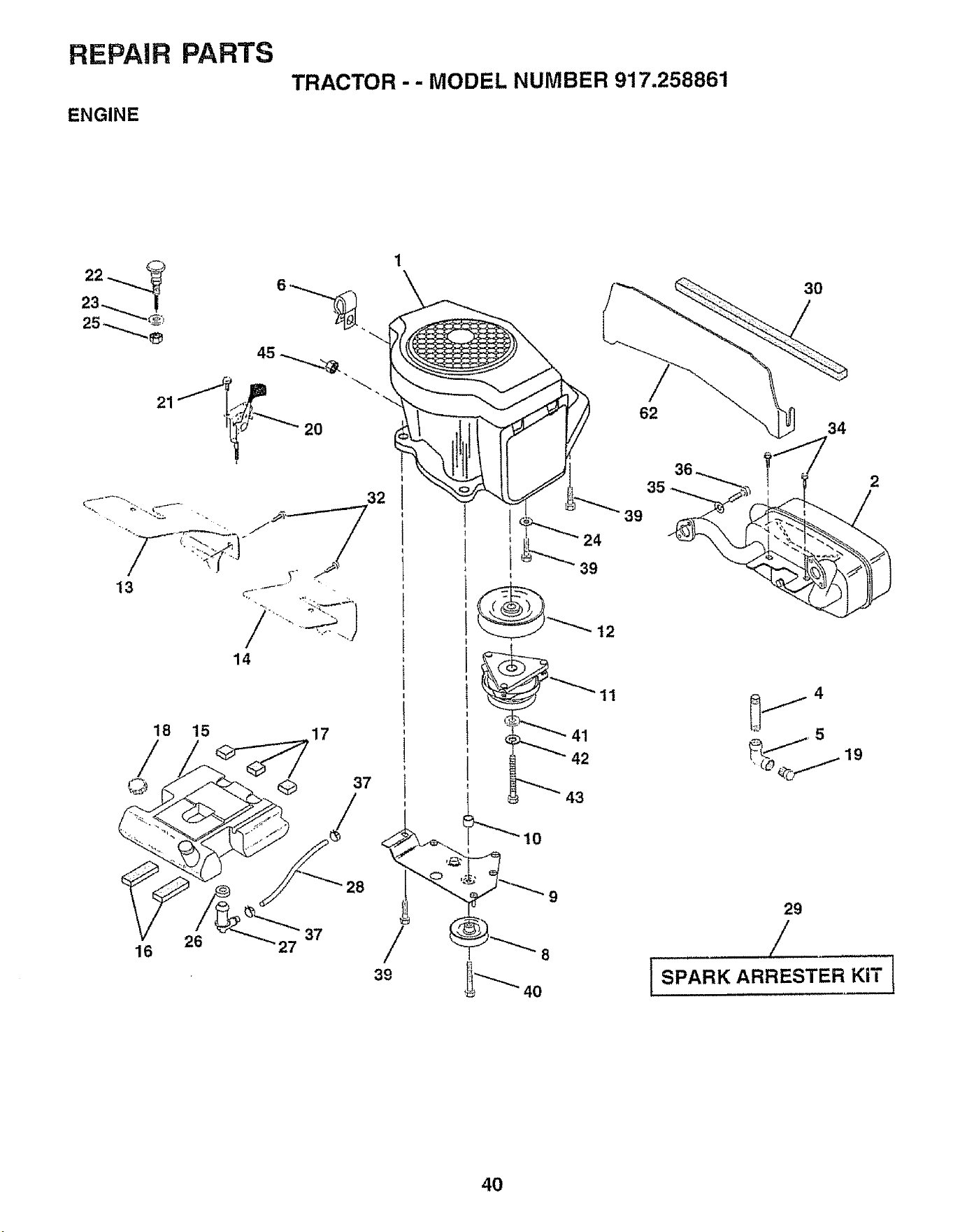
m _ I _lv
_0
_0
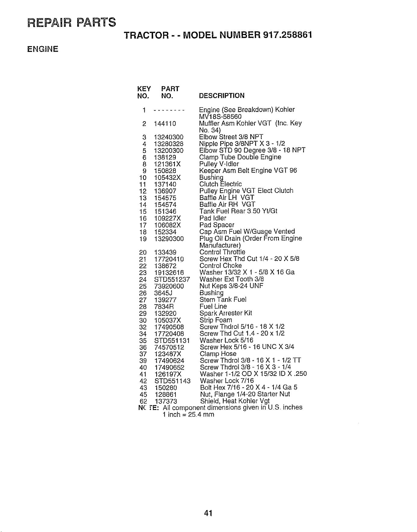
REPAIR PARTS
ENGINE
TRACTOR - - MODEL NUMBER 917.258861
KEY PART
NO. NO. DESCRIPTION
144110
3 13240300
4 13280328
5 13200300
6 138129
8 121361X
9 150828
I0 105432X
11 137140
12 136907
13 154575
14 154574
15 151346
16 109227X
17 106082X
18 152334
19 13290300
20 133439
21 17720410
22 138672
23 19132616
24 STD551237
25 73920600
26 3645J
27 139277
28 7834R
29 132920
30 I05037X
32 17490508
34 17720408
35 STD551131
36 74570512
37 123487X
39 17490624
40 17490652
41 126197X
42 STD55t143
43 150280
45 128861
62
N(:
Engine (See Breakdown) Kohler
MV18S-58560
Muffler Asm Kohler VGT (Inc. Key
No, 34)
Elbow Street 3/8 NPT
Nipple Pipe 3/8NPT X 3 - 1/2
Elbow STD 90 Degree 3/8 - t8 NPT
Clamp Tube DoubIe Engine
Pulley V-ldler
Keeper Asm Belt Engine VGT 96
Bushing
Clutch Electric
Pulley Engine VGT Elect Clutch
Baffle Air LH VGT
Baffle Air RH VGT
Tank Fuel Rear 350 Yt/Gt
Pad idler
Pad Spacer
Cap Asm Fuel W/Guage Vented
Plug Oil Drain (Order From Engine
Manufacturer)
Controt Throttle
Screw Hex Thd Cut 1/4 - 20 X 5/8
Control Choke
Washer' 13/32 X 1 - 5/8 X 16 Ga
Washer Ext Tooth 3/8
Nut Keps 3/8-24 UNF
Bushing
Stem Tank Fuel
Fuel Line
Spark At rester Kit
Strip Foam
Screw Thdrol 5/16 - t8 X 1/2
Screw Thd Cut 1.4 - 20 x 1/2
Washer Lock 5/16
Screw Hex 5/16 _ 16 UNC X 3/4
Clamp Hose
Screw Thdrot 3/8 - 16 X 1 - 1/2 TT
Screw Thdrol 3/8 - 16 X 3 - 1/4
Washer' 1-1/20D X 15/32 ID X _250
Washer Lock 7/16
Bolt Hex 7/16 _ 20 X 4 - 1/4 Ga 5
Nut, Flange 1/4-20 Starter Nut
137373 Shield, Heat KoHer Vgt
rE: All component dimensions given in U.S, inches
1 inch = 254 mm
41
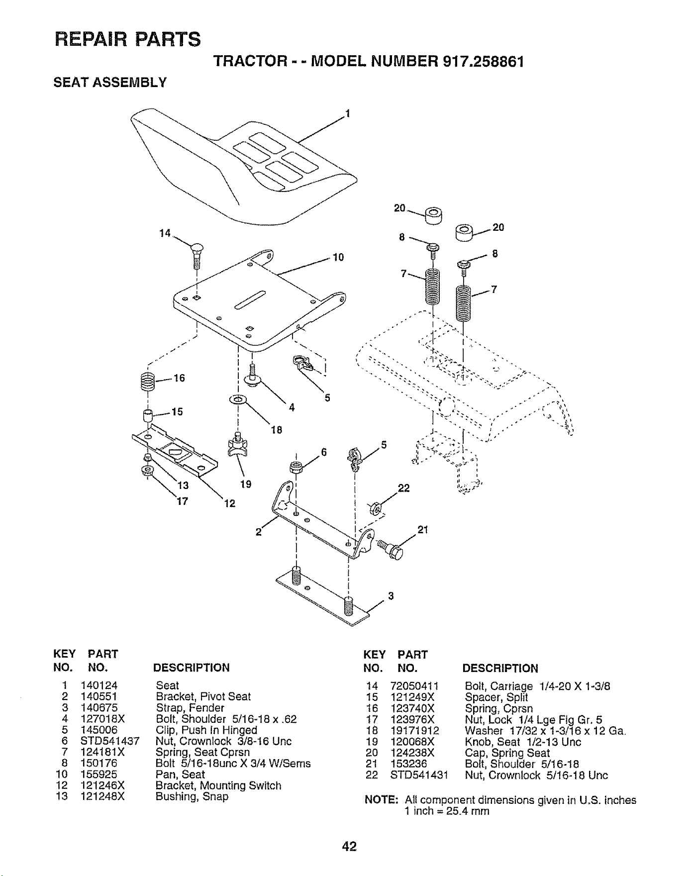
REPAIR PARTS
SEAT ASSEMBLY
TRACTOR -- MODEL NUMBER 917.258861
21
3
KEY
NO.
1
2
3
4
5
6
7
8
10
12
13
PART
NO,
140124
140551
140675
127018X
145006
STD541437
124181X
150176
155925
121246X
121248X
DESCRIPTION
Seat
Bracket, Pivot Seat
Strap, Fender
Bolt, Shoulder 5/16-t8 x .62
Clip, Push In Hinged
Nut, Crownlock 3/8-16 Uric
Spring, Seat Cprsn
Bolt 5/16-18unc X 3/4 W/Seres
Pan, Seat
Bracket, Mounting Switch
Bushing, Snap
KEY PART
NO. NO.
14 72050411
t5 121249X
t6 123740X
t7 123976X
18 19171912
19 120068X
20 124238X
21 153236
22 STD541431
DESCRIPTION
Bolt, Carriage 1/4-20 X 1-3/8
Spacer, Split
Spring, Cprsn
Nut, Lock 1/4 Lge Fig Gr. 5
Washer 17/32 x 1-3/16 x 12 Ga.
Knob, Seat 1/2-13 Unc
Cap, Spring Seat
Bolt, Shoulder 5/16-18
Nut, Crownlock 5/16-18 Uric
NOTE: All component dimensions given in U.S. inches
1 inch = 25.4 mm
42
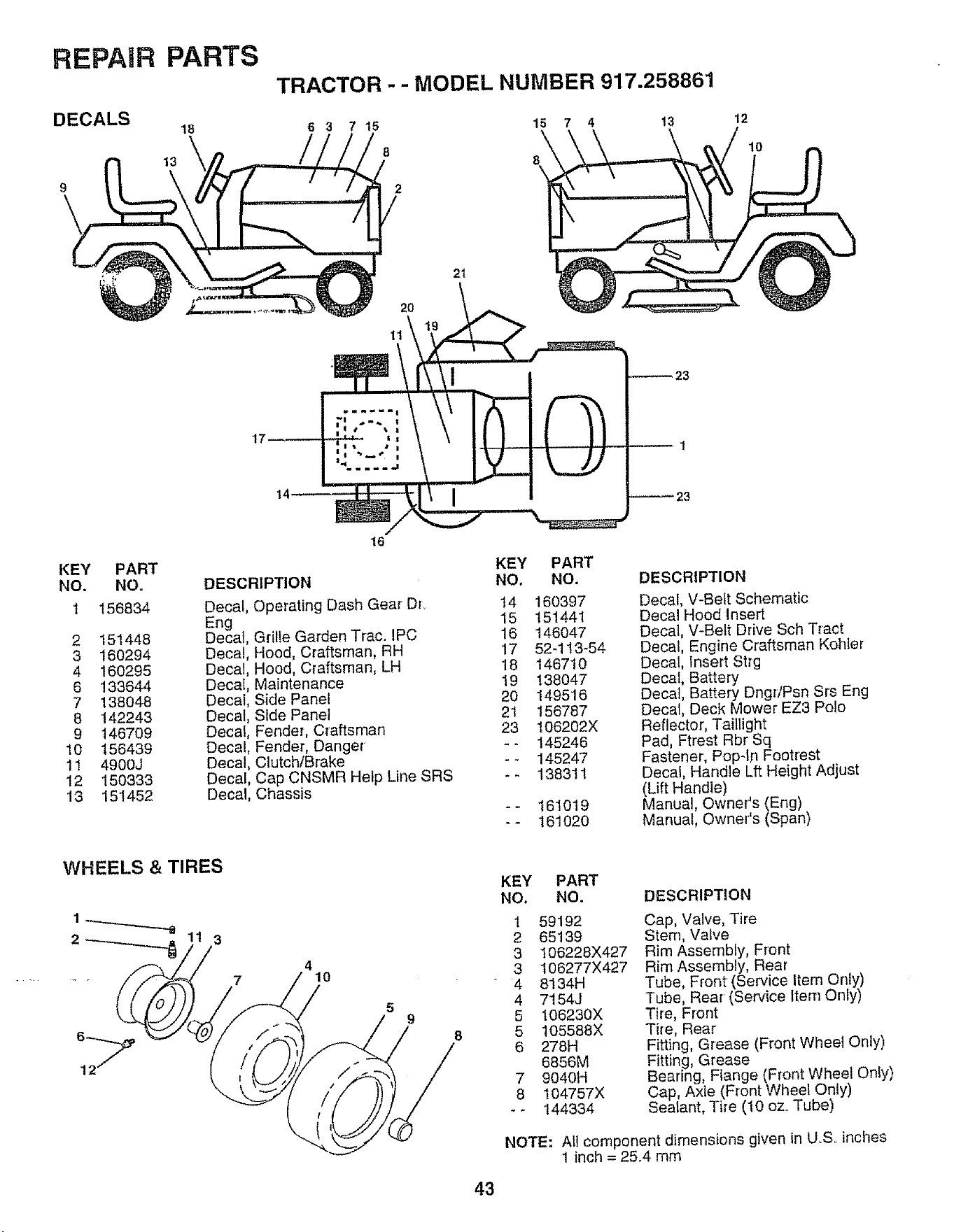
REPAIR PARTS
DECALS
18
13
9
TRACTOR - - MODEL NUMBER 917.258861
6 3 15 7 4 13 12
10
8
7 15
8
21
20
11
14
KEY PART
NO. NO.
1 156834 Decal
Eng
2 151448 Decal
3 160294 Decal
4 160295 Decal
6 133644 Decal
7 138048 Decal
8 142243 Decal
9 146709 Decal
10 156439 Decal
11 4900J Decal
12 150333 Decal
13 151452 Deca
16
DESCRIPTION
Operating Dash Gear Dr.
Grille Garden Trac. IPC
Hood, Craftsman, RH
Hood, Craftsman, LH
Maintenance
Side Panel
Side Pane_
Fender, Craftsman
Fender, Danger
Clutch/Brake
Cap CNSMR Help Line SRS
Chassis
WHEELS & TIRES
2
3
7
4
10
5
9
8
KEY PART
NO, NO.
14 160397
15 151441
16 146047
17 52q13-54
18 146710
19 138047
20 149516
21 156787
23 106202X
-- 145246
-- 145247
-- 138311
161019
161020
DESCRIPTION
Decal, V-Belt Schematic
Decal Hood Insert
Decal, V-Belt Drive Sch Tract
DecaJ, Engine Craftsman Kohler
Decal, Insert Strg
Decal, Battery
Decal, Battery DngdPsn Srs Eng
Decal, Deck Mower EZ3 Polo
Reflector, Taillight
Pad, Ftrest Rbr Sq
Fastener, Pop-In Footrest
Decal, Handle Lft Height Adjust
(Lift Handle)
Manual, Owner's (Eng)
Manual, Owner's (Span)
KEY PART
NO. NO.
1 59192
2 65139
3 106228X427
3 106277X427
4 8134H
4 7154J
5 106230X
5 105588X
6 278H
6856M
7 9040H
8 1Q4757X
-_ 144334
DESCRIPTION
Cap, Valve, Tire
Stem, Valve
Rim Assembly, Front
Rim Assembly, Rear
Tube, Front (Service Item Only)
Tube, Rear (Service Item Only)
Tire, Front
Tire, Rear'
Fitting, Grease (Front Wheel Only)
Fitting, Grease
Bearing, Flange (Front Wheel Only)
Cap, Axle (Front Wheel Only)
Sealant, Tile (10 oz Tube)
NOTE: All component dimensions given in U.So inches
1 inch = 25.4 mm
43
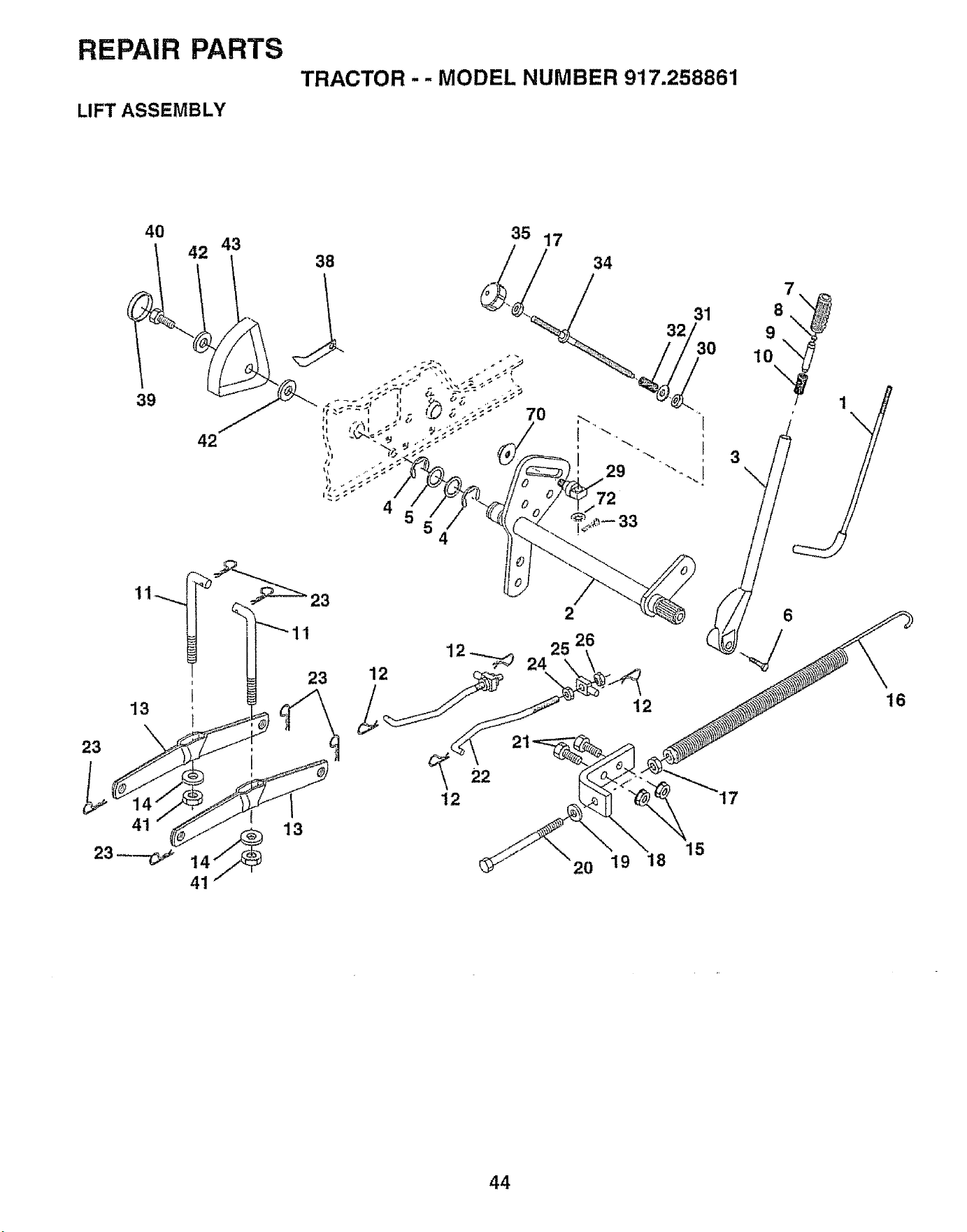
REPAIR PARTS
LIFT ASSEMBLY
TRACTOR - - MODEL NUMBER 917.258861
40
42 43
35 17
39
42
38 34
12_ 2425
22
12
2
26
12
20 19 18
15
44
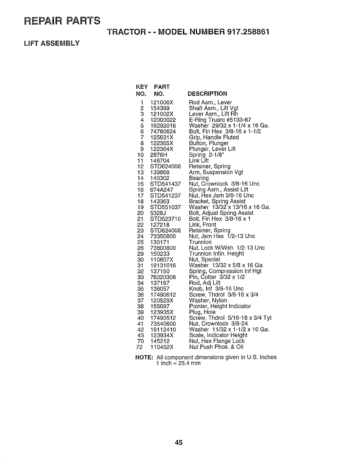
REPAHR PARTS
LIFT ASSEMBLY
TRACTOR - - MODEL NUMBER 917.258861
KEY PART
NO, NO.
1 121006X
2 154389
3 121002X
4 12000022
5 19292016
6 74780624
7 125631X
8 I22365X
9 122364X
10 2876H
11 146704
!2 STD624008
13 139868
14 140302
15 STD541437
16 674A247
17 STD541237
18 143363
19 STD551037
20 5328J
21 STD523710
22 127218
23 STD824008
24 73350800
25 130171
26 738OO8OO
29 150233
30 110807X
31 19131016
32 137150
33 76020308
34 137167
35 138057
36 17490612
37 120529X
38 155097
39 123935X
40 17490512
41 73540600
42 19112410
43 123934X
70 145212
72 110452X
DESCRIPTION
Rod Asm., Lever
Shaft Asm. Lift Vgt
Lever Asm. Lift Rh
E-Ring Truarc #5133-87
Washer 29/32 x t-1/4 x 16 Ga.
Bolt, Fin Hex 3/8-16 x 1-1/2
Grip, Handle Fluted
Button, Plunger
Plunger, Lever Lift
Spring 2-1/8"
Link Lift
Retainer', Spring
Arm, Suspension Vgt
Bearing
Nut, Crownlock 3/8-16 Unc
Spring Asmo, Assist Lift
Nut, Hex Jam 3/8-16 Uric
Bracket, Spring Assist
Washer 13/32 x 13/16 x 16 Ga.
Bolt, Adjust Spring Assist
Bolt, Fin Hex 3/8q6 x 1
Link, Front
Retainer, Spdng
Nut, Jam Hex 1/2-t3 Unc
Trunnion
Nut, Lock W/Wsh 1/2-t3 Unc
Trunnion Infin° Height
Nut, Special
Washe_ 13/32 x 5/8 x 16 Ga,
Spdng, Compression Inf Hgt
Pin, Cotter 3/32 x 1/2
Rod, Adj Lift
Knob, Inf 3/8-16 Unc
Screw, Thdrol 3/8-16 x 3/4
Washer, Nylon
Pointer, Height Indicator
Plug, Hole
Screw, Thdrol 5/16-18 x 3/4 Tyt
Nut, Crownlock 3/8-24
Washer !!/32 x 1-1/2 x 10 Gao
Scale, Indicator Height
Nut, Hex Flange Lock
Nut Push Phos, & Oil
NOTE: All component dimensions given in U.So inches
1 inch = 25..4 mm
45
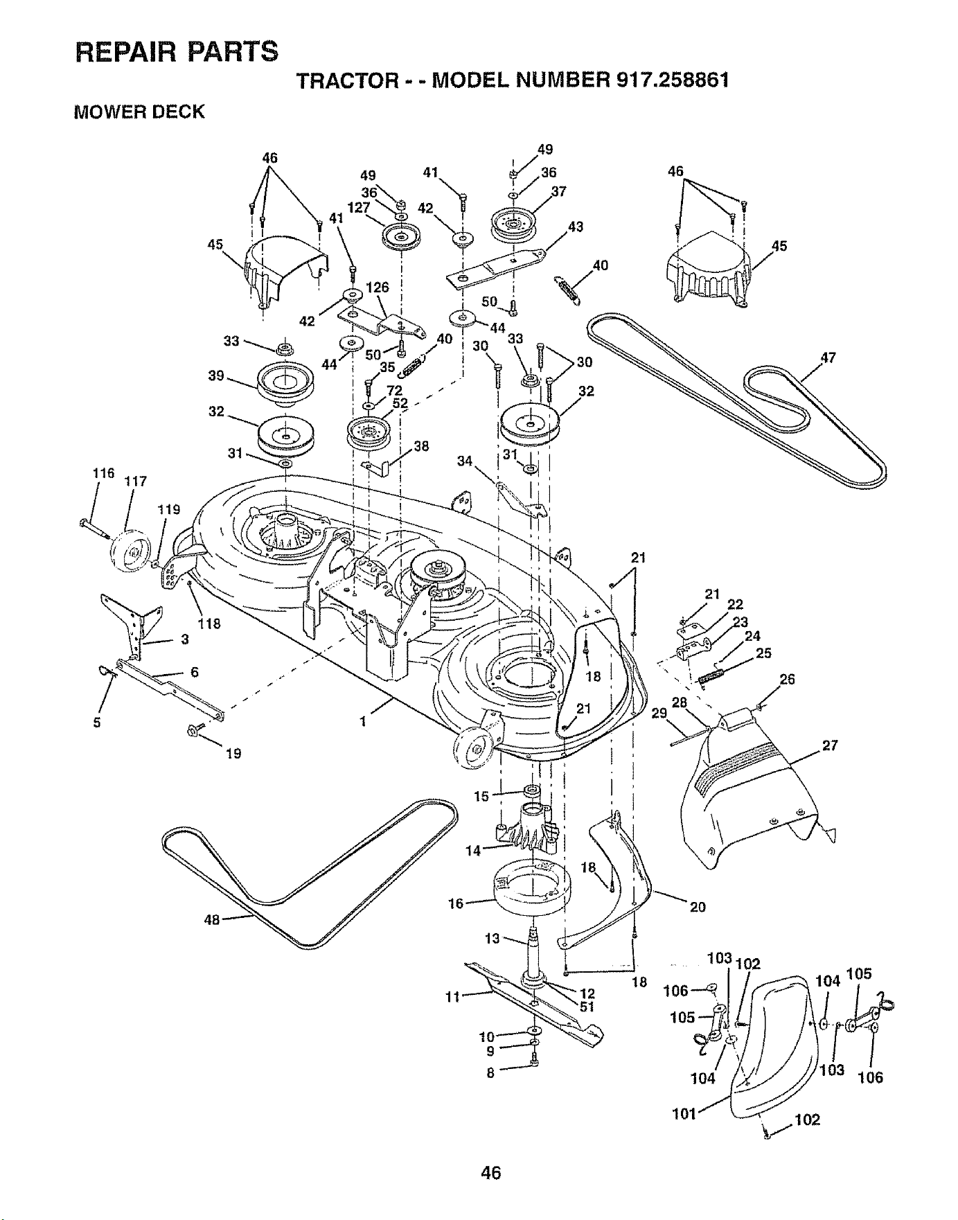
REPAIR PARTS
MOWER DECK
TRACTOR - - MODEL NUMBER 917.258881
116
t17
Z
31
32
119
118
f
19
21
46
21
3
24
25
28"
26
27
_0
.... ..... 103102
18 106---_
105
104
101
106
46
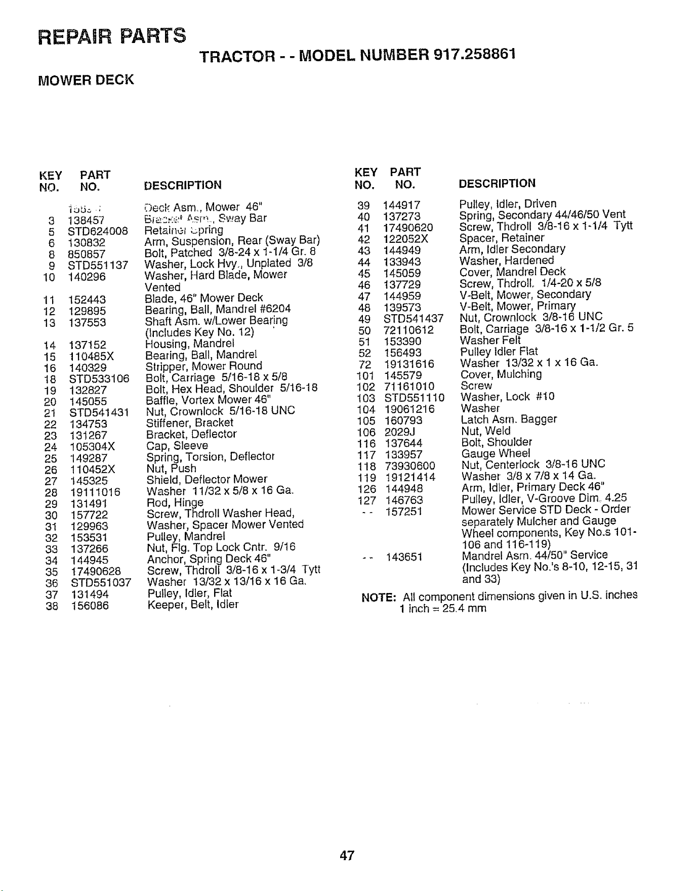
REPAIR PARTS
MOWER DECK
TRACTOR - - MODEL NUMBER 917.258861
KEY PART
NO. NO.
]_ ;
3 138457
5 STD624008
6 130832
8 850857
9 STD55!137
10 140296
11 152443
t2 129895
13 137553
14 137152
15 110485X
16 140329
18 STD533106
19 132827
2O 145O55
21 STD541431
22 134753
23 131267
24 105304X
25 149287
26 110452X
27 145325
28 19111016
29 131491
30 157722
3I 129963
32 153531
33 137266
34 144945
35 17490628
36 STD551037
37 131494
38 156086
DESCRIPTION
;3eck Asm, Mower 46"
Bi.,..:.:...:_::_z,_m., Sv_.,ayBar
Retainer ;_pring
Arm, Suspension, Rear (Sway Bar)
Bolt, Patched 3/8-24 x 1-!/4 Gr. 8
Washer, Lock Hvy. Unplated 3/8
Washer, Hard Blade, Mower
Vented
Blade, 46" Mower Deck
Bearing, Ball, Mandrel #6204
Shaft Asm. wlLower Bear!rig
(includes Key No. 12)
Housing, Mandrel
Bearing, Bali, Mandrel
Stripper, Mower Round
Bolt, Carriage 5/16-I8 x 5/8
Bolt, Hex Head, Shoulder 5/16-18
Baffle, Vortex Mower 46"
Nut, Crownlock 5/16-18 UNC
Stiffener, Bracket
Bracket, Deflector
Cap, Sleeve
Spring, Torsion, Deflector
Nut, Push
Shield, Deflector Mower'
Washer 11/32 x 5/8 x t6 Ga.
Rod, Hinge
Screw, Thdrol! Washer Head,
Washer, Spacer Mower Vented
Pulley, Mandrel
Nut, Flg.. Top Lock Cntro. 9/t6
Anchor, Spring Deck 46
Screw, Thdrell 3/8-16 x 1-3/4 Tytt
Washer !3/32 x 13/t6 x 16 Ga.
Pulley, Idler', Flat
Keeper, Belt, Idler
KEY PART
NO. NO, DESCRIPTION
39 144917
40 137273
41 17490620
42 122052X
43 144949
44 133943
45 145059
46 137729
47 144959
48 139573
49 STD541437
50 72110612
51 153390
52 156493
72 19131616
I01 145579
102 71161010
103 STD551110
104 19061216
105 160793
106 2029J
116 137644
117 133957
118 73930600
119 19121414
126 144948
127 146763
-- 157251
143651
Pulley, Idler, Driven
Spring, Secondary 44/46/50 Vent
Screw, Thdroll 3/8-16 x 1-114 Tytt
Spacer, Retainer
Arm, Idler' Secondary
Washer, Hardened
Cover; Mandrel Deck
Screw, ThdrolL t/4-20 x 5/8
V-Belt, Mower, Secondary
V-Belt, Mower, Primary
Nut, Crownlock 3/8-16 UNC
Bolt, Carriage 3/8-16 x 1-1/2 Gr. 5
Washer' Felt
Pulley Idler Flat
Washer 13/32 x 1 x 16 Ga.
Cover, Mulching
Screw
Washer, Lock #t0
Washer
Latch Asm.. Bagger
Nut, Weld
Bolt, Shoulder
Gauge Wheel
Nut, Centerlock 3/8_16 UNC
Washer 3/8 x 7/8 x 14 Ga..
Arm, Idler, Primary Deck 46"
Pulley, Idler, V-Groove Dim. 4.25
Mower Service STD Deck - Order'
separately Mulcher and Gauge
Wheel components, Key No.s 101-
106 and 116-119)
Mandrel Asm. 44/50" Service
(includes Key No.'s 8-10, 12-15, 31
and 33)
NOTE: All component dimensions given in U.S. inches
1 inch = 25.4 mm
47
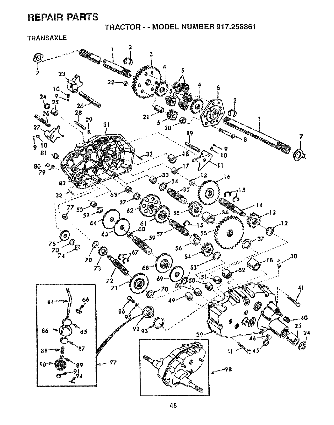
REPAIR PARTS
TRANSAXLE
TRACTOR - - MODEL NUMBER 917.258861
31
t
1 2
I
4
15
7
62
72
71
24
48
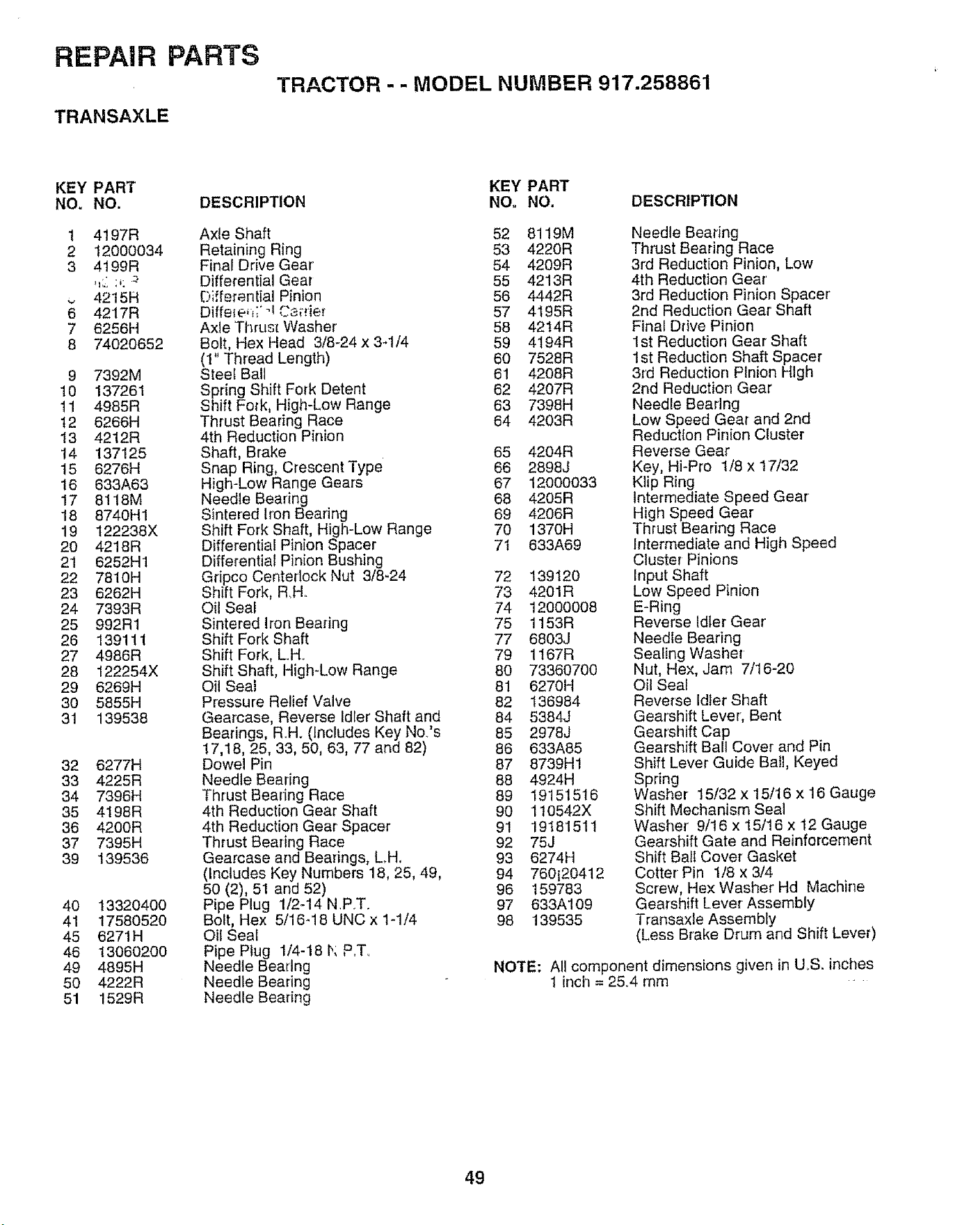
REPAIR PARTS
TRANSAXLE
TRACTOR - - MODEL NUMBER 917.258861
KEY PART
NO. NO.
1 4197R
2 12000034
3 4t9gR
42t5H
6 4217R
7 6256H
8 74020652
9 7392M
10 137261
11 4985R
t2 6266H
13 4212R
14 137125
15 6276H
16 633A63
17 8118M
18 8740H1
19 122236X
20 4218R
21 6252H1
22 781 OH
23 6262H
24 7393R
25 992R1
26 139111
27 4986R
28 122254X
29 6269H
30 5855H
31 139538
32 6277H
33 4225R
34 7396H
35 4198R
36 4200R
37 7395H
39 139536
40 13320400
41 17580520
45 6271H
46 13060200
49 4895H
50 4222R
51 1529R
DESCRIPTION
Axle Shaft
Retaining Ring
Final Drive Gear'
Differential Gear
Differentia] Pinion
Diffeteq;' q Ca_rier
Axle Thrust Washer
Bolt, Hex Head 3/8-24 x 3-1/4
(1" Thread Length)
Steel Bali
Spring Shift Fork Detent
Shift Fork, High-Low Range
Thrust Bearing Race
4th Reduction Pinion
Shaft, Brake
Snap Ring, Crescent Type
High-Low Range Gears
Needle Bearing
Sintered Iron Bearing
Shift Fork Shaft, High-Low Range
Differential Pinion Spacer
Differential Pinion Bushing
Gripco Centedock Nut 3/8-24
Shift Fork, R,H..
Oil Seal
Sintered Iron Bearing
Shift Fork Shaft
Shift Fork, LH.
Shift Shaft, High-Low Range
Oil Seal
Pressure Relief Valve
Gearcase, Reverse Idler' Shaft and
Bearings, R.H. (Includes Key No's
17,18, 25, 33, 50, 63, 77 and 82)
Dowel Pin
Needle Bearing
Thrust Bearing Race
4th Reduction Gear Shaft
4th Reduction Gear Spacer
Thrust Bearing Race
Gearcase and Bearings, LH.
(Includes Key Numbers 18, 25, 49,
50 (2), 51 and 52)
Pipe Plug 1/2-14 N.P.T.
Bolt, Hex 5/16-18 UNC x 1-1/4
Oil Seal
Pipe Plug 1/4-18 I,; P..T_
Needle Beartng
Needle Bearing
Needle Bearing
KEY PART
NO. NO. DESCRIPTION
52 8119M
53 4220R
54 4209R
55 4213R
56 4442R
57 4195R
58 4214R
59 4194R
60 7528R
61 4208R
62 4207R
63 7398H
64 4203R
65 4204R
66 2898J
67 12000033
68 4205R
69 4206R
70 1370H
7I 633A69
72 139120
73 4201R
74 12000008
75 1153R
77 6803J
79 1167R
80 73360700
81 6270H
82 136984
84 5384J
85 2978J
86 633A85
87 8739H1
88 4924H
89 19151516
90 110542X
91 19181511
92 75J
93 6274H
94 760i20412
96 159783
97 633A109
98 139535
Needle Beadng
Thrust Bearing Race
3rd Reduction Pinion, Low
4th Reduction Gear'
3rd Reduction Pinion Spacer
2nd Reduction Gear' Shaft
Final Drive Pinion
1st Reduction Gear Shaft
1st Reduction Shaft Spacer
3rd Reduction Pinion High
2rid Reduction Gear
Needle Bearing
Low Speed Gear and 2rid
Reduction Pinion Cluster
Reverse Gear
Key, Hi-Pro 1/8 x 17/32
Klip Ring
Intermediate Speed Gear
High Speed Gear
Thrust Bearing Race
Intermediate and High Speed
Cluster Pinions
Input Shaft
Low Speed Pinion
E-Ring
Reverse Idler Gear
Needle Bearing
Sealing Washer
Nut, Hex, Jam 7/16-20
Oil Seal
Reverse Idler Shaft
Gearshift Lever', Bent
Gearshift Cap
Gearshift Ball Cover and Pin
Shift Lever Guide Ball, Keyed
Spring
Washer 15/32 x 15/16 x 16 Gauge
Shift Mechanism Seal
Washer 9/16 x 15/16 x 12 Gauge
Gearshift Gate and Reinforcement
Shift Ball Cover Gasket
Cotter Pin 1/8 x 3/4
Screw, Hex Washer Hd Machine
Gearshift Lever Assembly
Transaxle Assembly
(Less Brake Drum and Shift Lever)
NOTE: All component dimensions given in UoS. inches
1 inctl = 2&4 mm
49
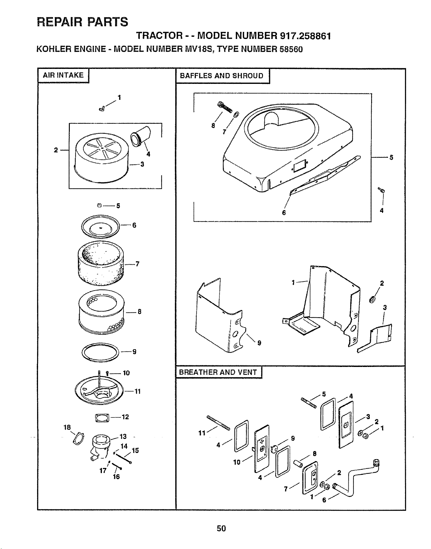
REPAIR PARTS
TRACTOR - - MODEL NUMBER 917.258861
KOHLER ENGINE - MODEL NUMBER MV18S, TYPE NUMBER 58560
i
l
J
6--5
_12
18
14
_ 15
16
i i
BAFFLES AND SHROUD I
/
8
7
/
6
_5
%
I
4
2
{
3
BREATHER AND VENT ]
,..--_"[[_a][i=_F
7J]!_¢@_I I
50
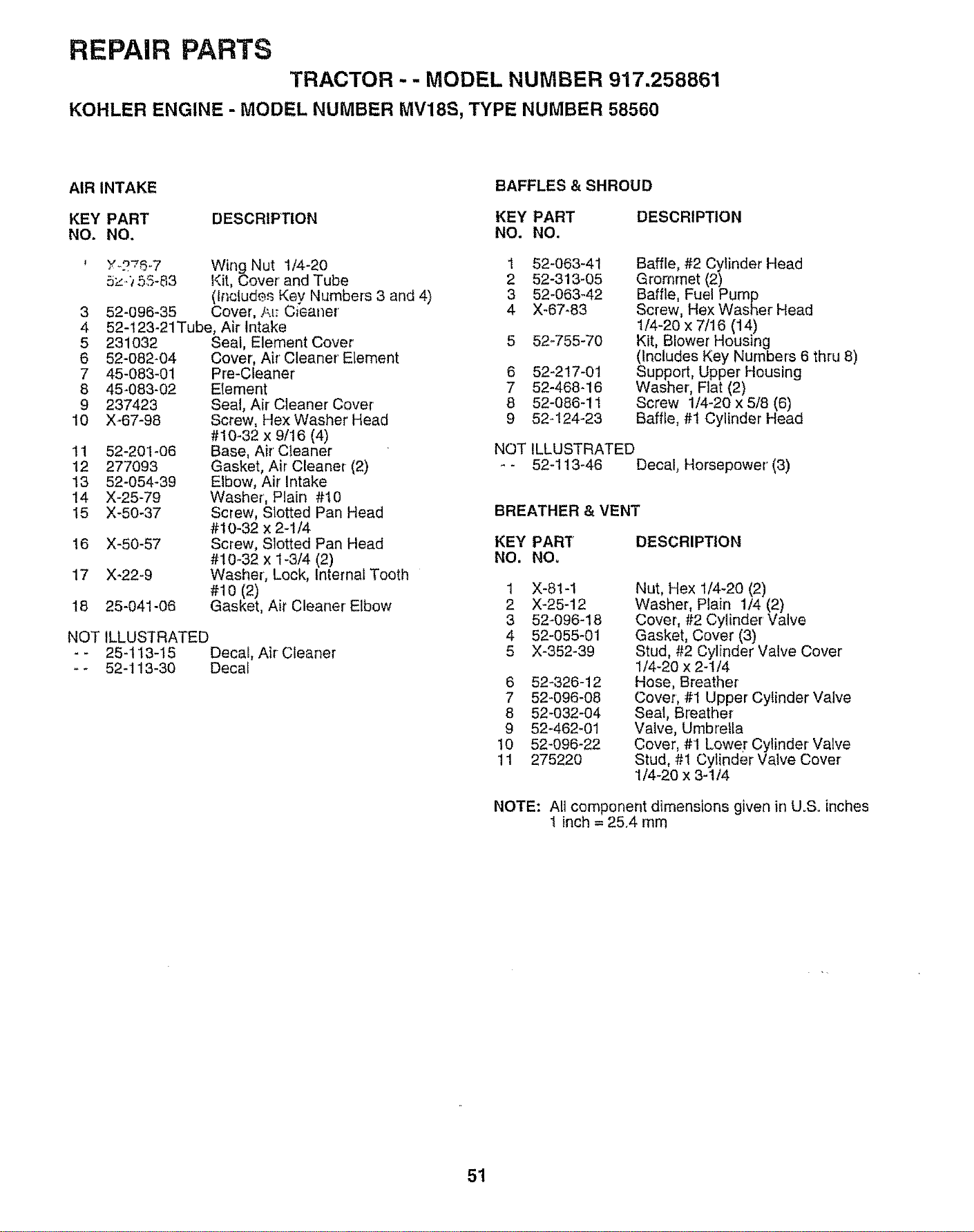
REPAIR PARTS
TRACTOR - - MODEL NUMBER 917.258861
KOHLER ENGINE - MODEL NUMBER MV18S, TYPE NUMBER 58560
AIR INTAKE
BAFFLES & SHROUD
KEY PART DESCRIPTION KEY PART
NO. NO. NO. NO.
'/-2-'._-7 Wing Nut t/4-20 1
5z-_ 55-83 Kit, Cover and Tube 2
(tr_cludesKey Numbers 3 and 4) 3
52-096-35 Cover, AI; Cieaner 4
52-123-21Tube, Air Intake
3
4
5 231032
6 52-082-04
7 45-083-01
8 45-083-02
9 237423
10 X-67-98
11 52-201-06
12 277093
13 52-054-39
14 X-25-79
15 X-50-37
16 X-50-57
17 X-22-9
Seal, Element Cover
Cover, Air' Cleaner Element
Pre-Cleaner
EIement
Seal, Air Cleaner Cover
Screw, Hex Washer' Head
#10-32 x 9/16 (4)
Base, Air Cleaner
Gasket, Air Cleaner (2)
Elbow, Air Intake
Washer', Plain #10
Screw, Slotted Pan Head
#10-32 x 2-1/4
Screw, Slotted Pan Head
#10-32 x 1-3/4 (2)
Washer', Lock, Internal Tooth
#10 (2)
Gasket, Air Cleaner Elbow
18 25-041-06
NOT ILLUSTRATED
- 25-t13-15 Decal, Air Cleaner
* 52-t13-30 Decal
DESCRIPTION
6
7
8
9
52-063-41
52-313-05
52-063-42
X-67-83
52-755-70
52-217-01
52-468-16
52-086-11
52-124-23
Baffle, #2 Cylinder Head
Grommet (2)
Baffle, Fuel Pump
Screw, Hex Washer Head
1/4-20 x 7t16 (14)
Kit, Blower Housing
(Includes Key Numbers 6 thru 8)
Suppert, Upper Housing
Washer, Flat (2)
Screw 1/4-20 x 5/8 (6)
Baffle, #1 Cylinder Head
NOT ILLUSTRATED
- 52-113-46 Decal, Horsepower (3)
BREATHER & VENT
DESCRIPTION
1
2
3
4
5
X-81-1
X-25-12
52-096-18
52-055-01
X-352-39
6 52-326-12
7 52-096-08
8 52-032-04
9 52-462-01
10 52-096-22
11 275220
Nut, Hex 1/4-20 (2)
Washer, Plain 1/4 (2)
Cover, #2 Cylinder' Valve
Gasket, Cover (3)
Stud, #2 Cylinder Valve Cover'
1/4-20 x 2-1/4
Hose, Breather
Cover', #1 Upper Cylinder Valve
Seal, Breather
Valve, Umbrella
Cover, #1 Lower Cylinder Valve
Stud, #1 Cylinder Valve Cover
1/4-20 x 3-1/4
NOTE: All cemponent dimensions given in U.& inches
1 inch = 25.4 mm
51
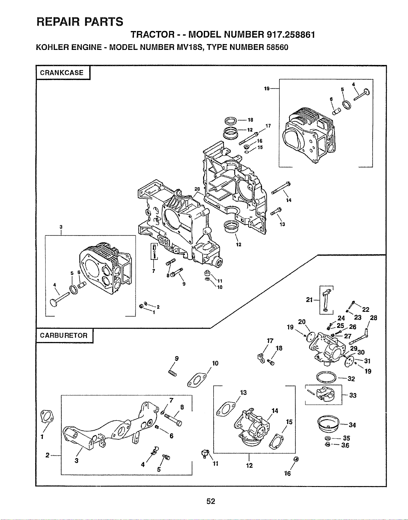
REPAIR PARTS
TRACTOR -- MODEL NUMBER 917.258861
KOHLER ENGINE - MODEL NUMBER MV18S, TYPE NUMBER 58560
CRANKCASEI
_)--18
19_
17
4
5
6
i == == ==
CARBURETOR I
9
9
/
%
5
14
13
\
12
10
1t 12 /
16
52
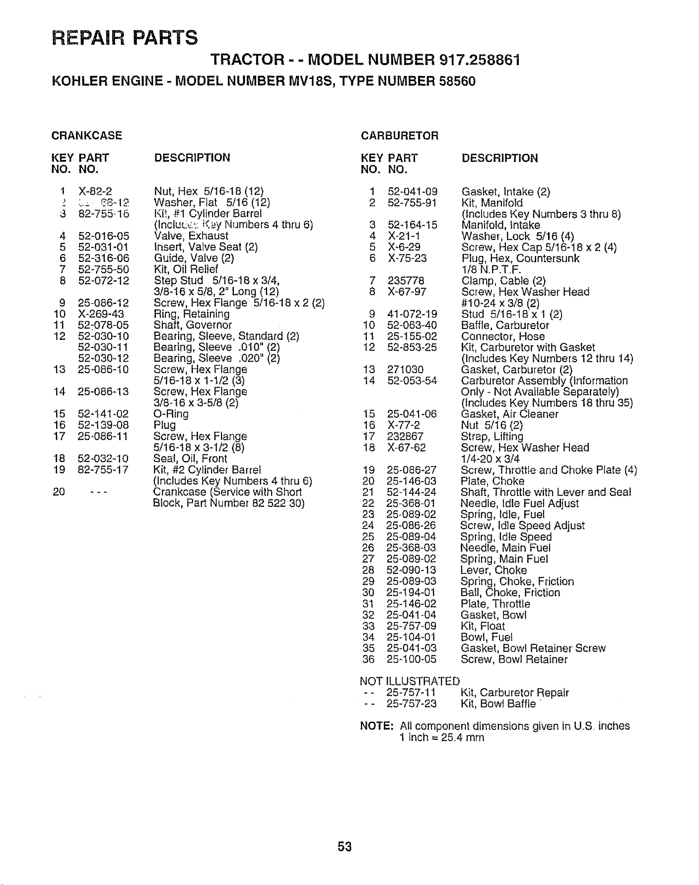
REPAIR PARTS
TRACTOR - - MODEL NUMBER 917.258861
KOHLER ENGINE - MODEL NUMBER MV18S, TYPE NUMBER 58560
CRANKCASE CARBURETOR
KEY PART DESCRIPTION KEY PART DESCRIPTION
NO, NO, NO. NO.
1 X-82-2
3 82-755..16
4 52-016-05
5 52-031-01
6 52-316-06
7 52-755-50
8 52-072-12
9 25_086-12
10 X_269-43
11 521078-05
12 52-030-t0
52-030-11
52-030-12
13 25-086-10
14 25-086q3
15 52-141-02
16 52-139-.08
17 25-086-11
18 52-032-10
19 82-755-17
Nut, Hex 5/16-18 (12) 1 52_04!-09
Washer, Flat 5/16 (12) 2 52-755-91
Ki!, #1 Cylinder Barrel
(Inciu_.,,_.::_<._yNumbers 4 thru 6) 3 52-164-15
Valve, Exhaust 4 X-21-1
Insert, Valve Seat (2) 5 X-6-29
Guide, Valve (2) 6 X-75-23
Kit, Oil Relief
Step Stud 5/16-18 x 3/4, 7 235778
3/8-16 x 5/8, 2" Long (12) 8 X-67-97
Screw, Hex Flange 5/16-18 x 2 (2)
Ring, Retaining 9 41-072-19
Shaft, Governor 10 52-063-40
Bearing, Sleeve, Standard (2) 11 25-155-02
Bearing, Sleeve .010" (2) 12 52-853-25
Bearing, Sleeve .020" (2)
Screw, Hex Flange t3 271030
5/16-18 x 1-t/2 (3) 14 52-053-54
Screw, Hex Flange
3/8-16 x 3-5/8 (2)
O-Ring 15 25-041-06
Plug 16 X-77-2
Screw, Hex Flange 17 232867
5/16-18 x 3-1/2 (8) 18 X-67-62
Seal, Oil, Front
Kit, #2 Cylinder Barrel
(Includes Key Numbers 4 thru 6)
Crankcase (Service with Short
Block, Part Number 82 522 30)
0 _-
19 25-086-27
20 25-146-03
21 52-144-24
22 25-368-0t
23 25_089-02
24 25-086-26
25 25-089-04
26 25-368-03
27 25-089-02
28 52_090-13
29 25-089-03
30 25-194-01
31 25-146-02
32 25-041-04
33 25-757-09
34 254 04-01
35 25-041-03
36 25_100-05
Gasket, Intake (2)
Kit, Manifold
(includes Key Numbers 3 thru 8)
Manifold, Intake
Washer', Lock 5/16 (4)
Screw, Hex Cap 5/16-18 x 2 (4)
Plug, Hex, Countersunk
1/8 N.P.TF.
Clamp, Cable (2)
Screw, Hex Washer' Head
#10-24 x 3/8 (2)
Stud 5/16-I8 x 1 (2)
Baffle, Carburetor
Connector, Hose
Kit, Carburetor with Gasket
(includes Key Numbers 12 thru 14)
Gasket, Carburetor (2)
Carburetor Assembly (information
Only - Not Available Separately)
(Includes Key Numbers 18 thru 35)
Gasket, Air Cleaner
Nut 5/16 (2)
Strap, Lifting
Screw, Hex Washer Head
1/4-20 x 3/4
Screw, Throttle and Choke Plate (4)
Plate, Choke
Shaft, Throttle with Lever and Seal
Needle, Idle Fuel Adjust
Spring, Idle, Fuel
Screw, Idle Speed Adjust
Spdng, Idle Speed
Needle, Main Fuel
Spdng, Main Fuel
Lever, Choke
Spring, Choke, Friction
Ball, Choke, Friction
Plate, Throttle
Gasket, Bow]
Kit, Float
Bow!, Fuel
Gasket, Bowl Retainer' Screw
Screw, Bowl Retainer
NOT ILLUSTRATED
-- 25-757-11 Kit, Carburetor Repair
- 25-757-23 Kit, Bowl Baffle
NOTE: All component dimensions given in U_S inches
1 inch = 25.4 mm
53
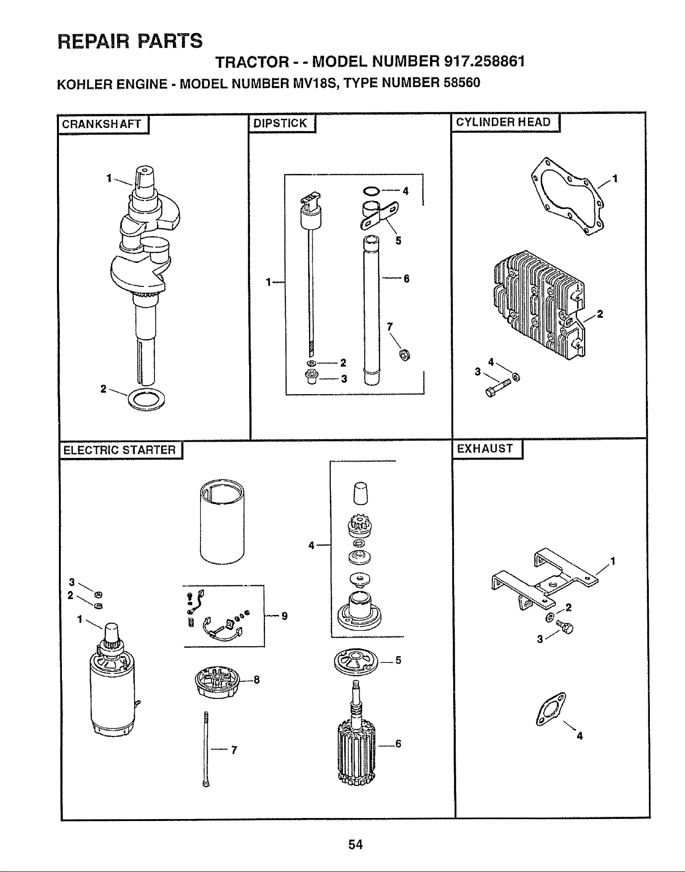
REPAIR PARTS
TRACTOR - - MODEL NUMBER 917.258861
KOHLER ENGINE - MODEL NUMBER MV18S, TYPE NUMBER 58560
CRANKSHAFT I
©
D,P'ST,CK!
' 0_4
w 6
i
7
\
ELECTRIC STARTER I
3_
2 '_
i
i
,=, I
1_'= w9
@y_8
J7
4_
J
' 8
@
@
Q
@
@
....
CYLINDER HEAD I
EXHAUSTI
4
54
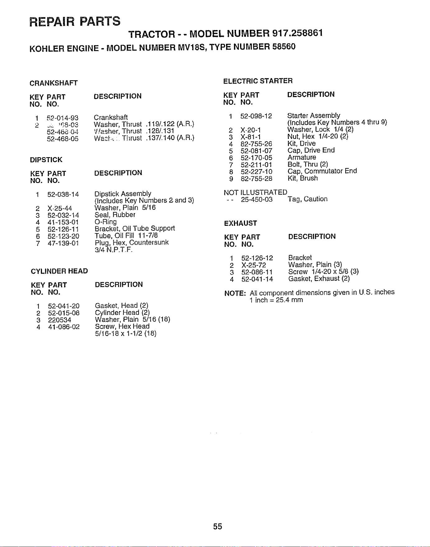
REPAIR PARTS
TRACTOR - - MODEL NUMBER 917,258861
KOHLER ENGINE - MODEL NUMBER MV18S, TYPE NUMBER 58560
CRANKSHAFT ELECTRIC STARTER
KEY PART DESCRIPTION KEY PART
NO. NO. NO, NO,
1 52-014-93
2 _;; %8-03
52-468.04
52-468-O5
DIPSTICK
KEY PART
NO. NO.
1 52-038d 4
2 X_25_44
3 52-032_14
4 41-153-01
5 52-126-11
6 52-123-20
7 47-139-01
CYLINDER HEAD
KEY PART
NO. NO,
Crankshaft
Washer, Thrust .119L122 (A.R.)
Washer, Thrust .128/o131
Wast_ : Thrust .137/.140 (A..R.)
DESCRIPTION
Dipstick Assembly
(Includes Key Numbers 2 and 3)
Washer, Plain 5/16
Sea!, Rubber
O-Ring
Bracket, Oil Tube Support
Tube, Oil Fill 11-7/8
Plug, Hex, Countersunk
3/4 N.P.T..F.
DESCRIPTION
Gasket, Head (2)
Cylinder Head (2)
Washer', Plain 5/16 (18)
Screw, Hex Head
5116-18 x 1-1t2 (18)
1 52-041-20
2 52-015-08
3 220534
4 41-086-02
DESCRIPTION
1 52-098-!2
2 X-20-1
3 X-81-1
4 82-755-26
5 52-081-07
6 52-170-05
7 52-211-01
8 52-227-10
9 82-755-28
Starter Assembly
(Includes Key Numbers 4 thru 9)
Washer, Lock 1/4 (2)
Nut, Hex 1/4-20 (2)
Kit, Drive
Cap, Drive End
Armature
Bolt, Thru (2)
Cap, Commutator End
Kit, Brush
NOT ILLUSTRATED
-- 25-450-03 Tag, Caution
EXHAUST
KEY PART DESCRIPTION
NO. NO.
1
2
3
4
52-126-12
X-25-72
52-086-11
52-041-14
Bracket
Washer, Plain (3)
Screw 1/4-20 x 5/8 (3)
Gasket, Exhaust (2)
NOTE: All component dimensions given in US. inches
1 inch = 25.4 mm
55
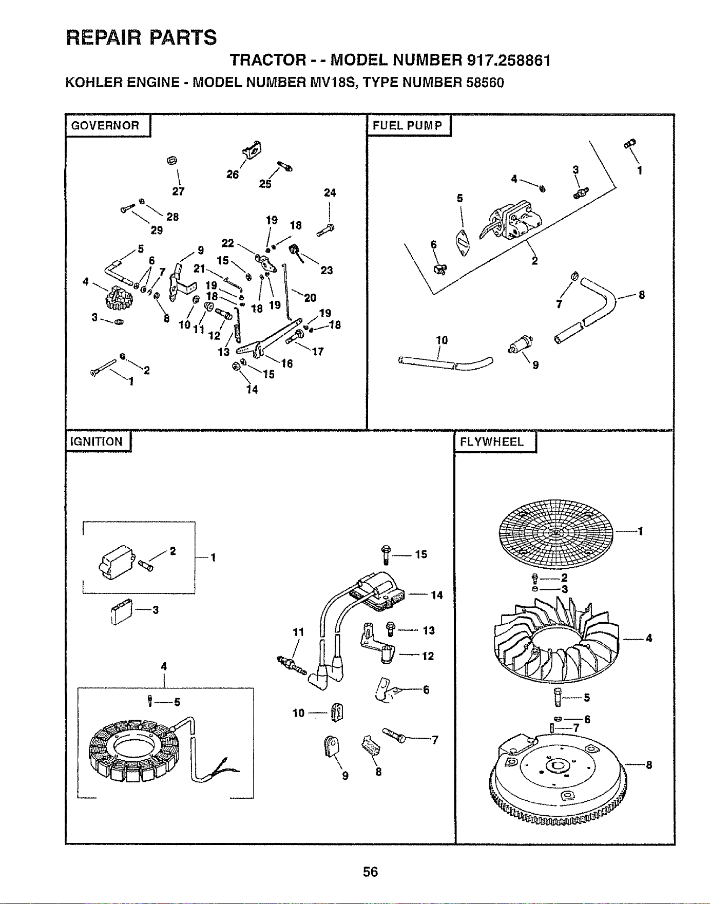
REPAIR PARTS
TRACTOR - - MODEL NUMBER 917.258861
KOHLER ENGINE - MODEL NUMBER MV18S, TYPE NUMBER 58560
GOVERNORI FUEL PUMP I
10
IGNITION I
9 8
6
1
FLYWHEEL,, I
_'m2
56
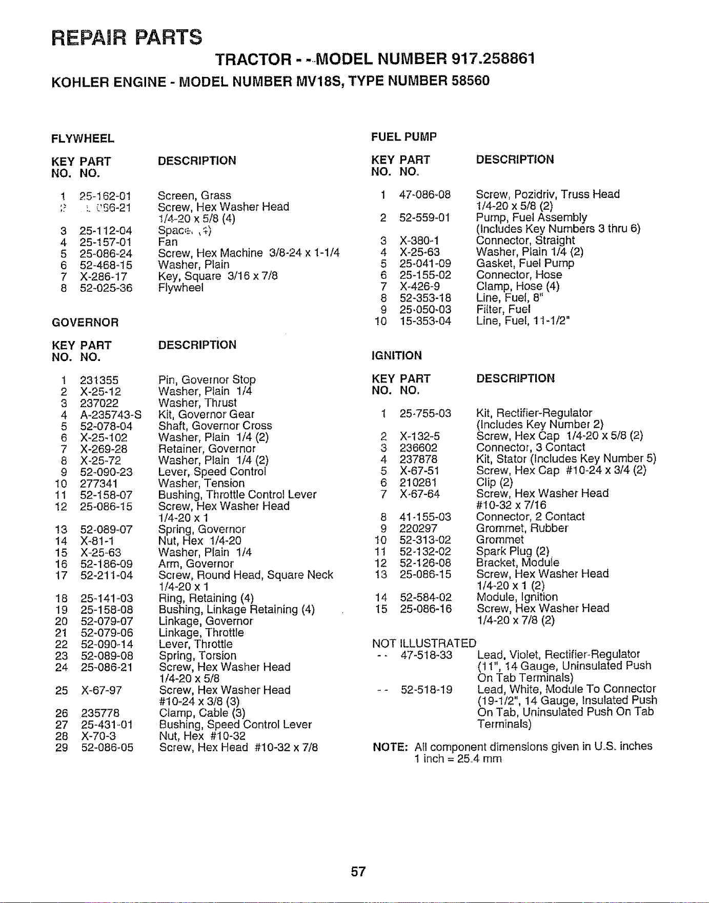
REPAHR PARTS
TRACTOR .... MODEL NUMBER 917.258861
KOHLER ENGINE - MODEL NUMBER MV18S_ TYPE NUMBER 58560
FLYWHEEL
FUEL PUMP
KEY PART DESCRIPTION KEY PART DESCRIPTION
NO. NO. NO. NO,
1 25-162-01 Screen, Grass
;? :. _J£6_21 Screw, Hex Washer Head
1/4-20 x 5/8 (4)
3 25-112-04 Space, ,_)
4 25-157-01 Fan
5 25-086-24 Screw, Hex Machine 3/8-24 x 1-1/4
6 52-468-15 Washer, Plain
7 X-286-17 Key, Square 3/16 x 7/8
8 52_025-36 Flywheel
GOVERNOR
KEY PART
NO. NO.
1 231355
2 X-25-12
3 237022
4 A-235743-S
5 52-078-04
6 X-25-102
7 X-269-28
8 X-25-72
9 52-09O-23
10 277341
11 52-158-07
12 25-086-15
13 52_089-07
14 X-81-1
15 X-25-63
16 52-186-09
17 52_211-04
18 25-141-03
19 25-158-08
20 52-079_07
21 52-079-06
22 52_090-!4
23 52-089-08
24 25-086-21
25 X_67-97
DESCRIPTION
Pin, Governor Stop
Washer', Ptain 1/4
Washer, Thrust
Kit, Governor Gear
Shaft, Governor' Cross
Washer, Plain 1/4 (2)
Retainer', Governor
Washer, Plain 1/4 (2)
Lever, Speed Control
Washer, Tension
Bushing, Throttle Control Lever
Screw, Hex Washer Head
1/4-20 x 1
Spring, Governor'
Nut, Hex 1/4-20
Washer', Plain 1/4
Arm, Governor'
Screw, Round Head, Square Neck
1/4-20 x 1
Ring, Retaining (4)
Bushing, Linkage Retaining (4)
Linkage, Governor'
Linkage, Throttle
Lever, Throttle
Spring, Torsion
Screw, Hex Washer Head
1/4-20 x 5/8
Screw, Hex Washer' Head
#10-24 x 3/8 (3)
Clamp, Cable (3)
Bushing, Speed Control Lever'
Nut, Hex #10-32
Screw, Hex Head #t0-32 x 7/8
26 235778
27 25-431_01
28 X-70-3
29 52-086-05
1 47-086-08
2 52-559-01
3 X-380_1
4 X_25-63
5 25-041-09
6 25-155_02
7 X-426-9
8 52-353-18
9 25.050-03
10 15_353-04
Screw, Pozidriv, Truss Head
I/4-20 x 5/8 (2)
Pump, Fuel Assembly
(Includes Key Numbers 3 thru 6)
Connector, Straight
Washer', Plain 1/4 (2)
Gasket, Fuel Pump
Connector', Hose
Clamp, Hose (4)
Line, Fuef, 8"
Filter, Fuel
Line, Fuel, 11-1/2"
IGNITION
KEY PART
NO, NO.
DESCRIPTION
2
3
4
5
6
7
25_755-03
X-132-5
236602
237878
X-67-51
210281
X-67-64
8 41-155-03
9 220297
10 52-313-02
11 52-132-02
12 52-126-08
13 25-086-15
14 52-584-02
15 25-086-16
Kit, Rectifier-Regulator
(Includes Key Number 2)
Screw, Hex Cap 1/4-20 x 5/8 (2)
Connector, 3 Contact
Kit, Stator (Includes Key Number' 5)
Screw, Hex Cap #10-24 x 3/4 (2)
Clip (2)
Screw, Hex Washer Head
#10-32 x 7/t6
Connector, 2 Contact
Grommet, Rubber'
Grommet
Spark Plug (2).
Bracket, Module
Screw, Hex Washer Head
114-20 x I (2)
Module, Ignition
Screw, Hex Washer Head
1/4-20 x 7/8 (2)
NOT ILLUSTRATED
-- 47-518-33 Lead, Violet, Rectifier-Regulator
(11", 14 Gauge, Uninsulated Push
On Tab Terminals)
-- 52-518-19 Lead, White, Module To Connector'
(19-1/2", 14 Gauge, Insulated Push
On Tab, Uninsulated Push On Tab
Terminals)
NOTE: All component dimensions given in US. inches
1 inch = 25,4 mm
57
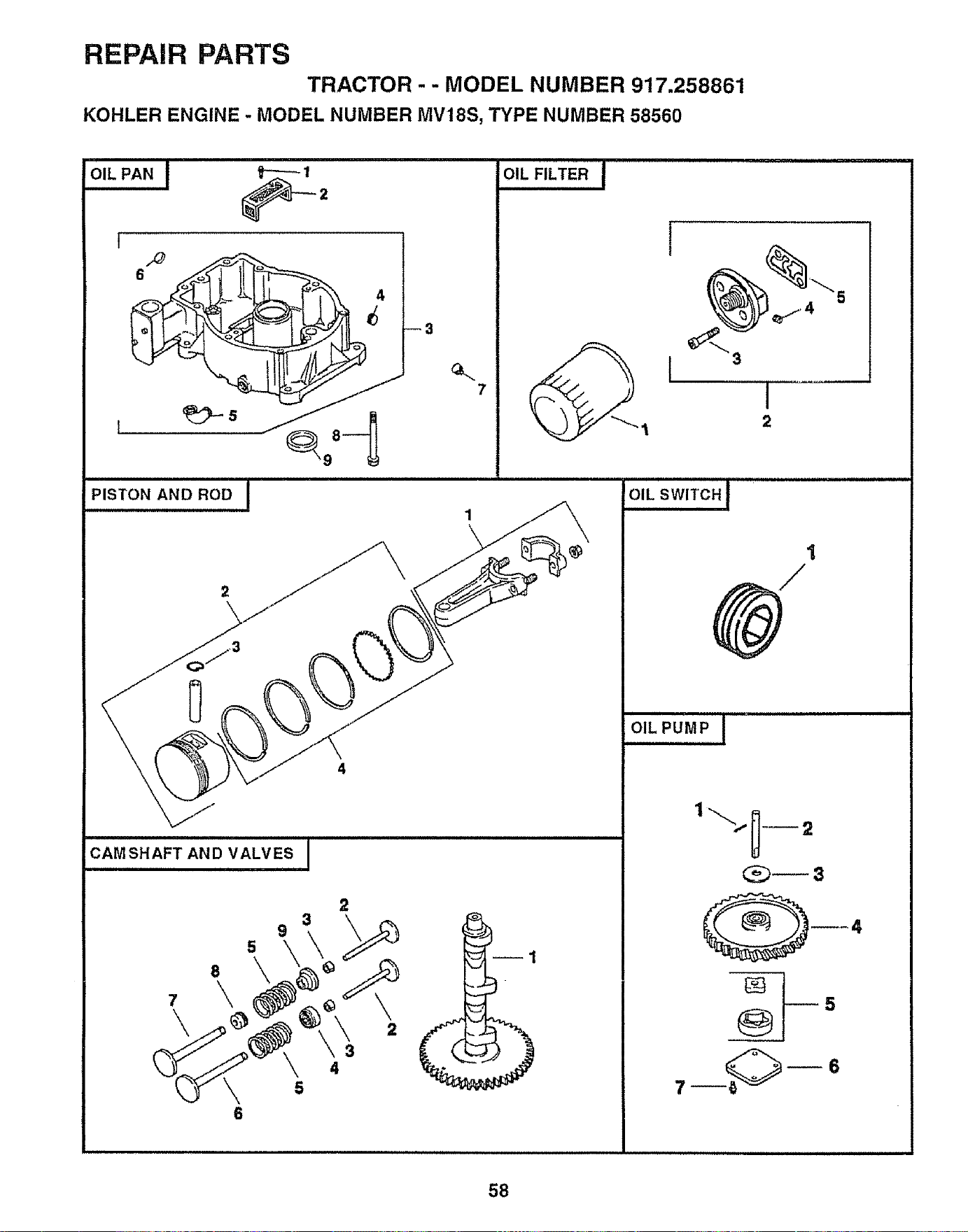
REPAIR PARTS
TRACTOR- - MODEL NUMBER 917,258861
KOHLER ENGINE - MODEL NUMBER MV18S, TYPE NUMBER 58560
PISTON AND ROD I
--3
OIL FILTER J
2
6
[
5
_3
I
2
IHIHIII=I, = = = == H I=III=H,IH==I=I,,==I=,II,IH,
OIL SWITCH
°'LPUMPI
7_ _6
58
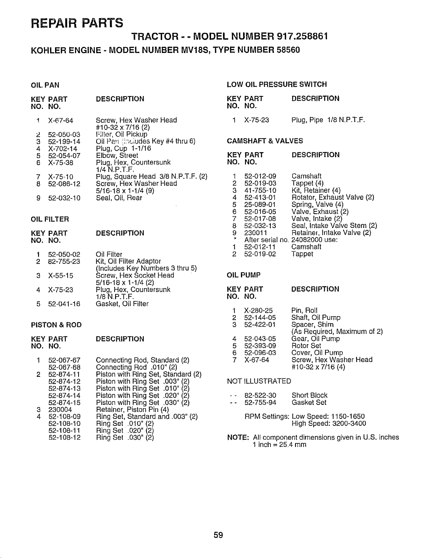
REPAIR PARTS
TRACTOR - - MODEL NUMBER 917,258861
KOHLER ENGINE - MODEL NUMBER MV18S, TYPE NUMBER 58560
OIL PAN
KEY PART DESCRIPTION
NO, NO.
! X-67-64
2 52-050-O3
3 52-199-14
4 X-702-14
5 52-054-07
6 X-75-38
7 X-75-10
8 52-086-12
9 52-032-10
OIL FILTER
KEY PART
NO. NO.
1 52-050-02
2 82-755-23
3 X-55-15
4 X-75-23
5 52-041-16
PISTON & ROD
KEY PART
NO. NO.
1 52-067-67
52-067-68
2 52-874-11
52-874-12
52-874-13
52-874-14
52-874-15
3 230004
4 52-108-09
52-108-10
52-108-11
52-108-12
Screw, Hex Washer Head
#10_32 x 7/16 (2)
Filter, Oil Pickup
Oil Pa!_ _,::',clude_Key #4 thru 6)
Plug, Cup 1-1/16
Elbow, Street
Plug, Hex, Countersunk
1/4 N.P.TrF.
Plug, Square Head 3/8 N.P.T.F. (2)
Screw, Hex Washer Head
5/16=18 x t-1/4 (9)
Seal, Oil, Rear
DESCRIPTION
Oil Filter
Kit, Oil Filter Adaptor
(Includes Key Numbers 3 thru 5)
Screw, Hex Socket Head
5/16-18 x 1-1/4 (2)
Plug, Hex, Countersunk
1/8 NP.T.F..
Gasket, Oil Filter'
DESCRIPTION
Connecting Rod, Standard (2)
Connecting Rod .010" (2)
Piston with Ring Set, Standard (2)
Piston with Ring Set ,003" (2)
Piston with Ring Set .010" (2)
Piston with Ring Set .020" (2)
Piston with Ring Set .030" (2)
Retainer', Piston Pin (4)
Ring Set, Standard and ..003" (2)
Ring Set o010" (2)
Ring Set .020" (2)
Ring Set .030" (2)
LOW OIL PRESSURE SWITCH
KEY PART DESCRIPTION
NO. NO.
t X-75-23 Plug, Pipe 1/8 N_P.ToF.
CAMSHAFT & VALVES
KEY PART
NO. NO.
DESCRIPTION
1 524012-09
2 52-019-03
3 41-755q 0
4 52-413-01
5 25-089_01
6 52-016-05
7 52_017-08
8 52-032-13
9 230011
* After serial no,.
1 52-012_11
2 52-019-02
Camshaft
Tappet (4)
Kit, Retainer (4)
Rotator, Exhaust Valve (2)
Spring, Valve (4)
Valve, Exhaust (2)
Valve, Intake (2)
Seal, Intake Valve Stem (2)
Retainer, Intake Valve (2)
24082000 use:
Camshaft
Tappet
OIL PUMP
KEY PART
NO. NO.
DESCRIPTION
1
2
3
4
5
6
7
X_280-25
52-144-05
52-422-01
52-043-05
52-393-09
52-096-03
X_67-64
Pin, Roll
Shaft, Oil Pump
Spacer, Shim
(As Required, Maximum of 2)
Gear, Oil Pump
Rotor Set
Cover, Oil Pump
Screw, Hex Washer Head
#t 0-32 x 7/t6 (4)
NOT ILLUSTRATED
- - 82-522-30
- - 52-755-94
Short Block
Gasket Set
RPM Settings: Low Speed: 1150-1650
High Speed: 3200-3400
NOTE: All component dimensions given in UoS, inches
1 inch = 25,4 mm
59

60

SERVICE NOTES
61

62
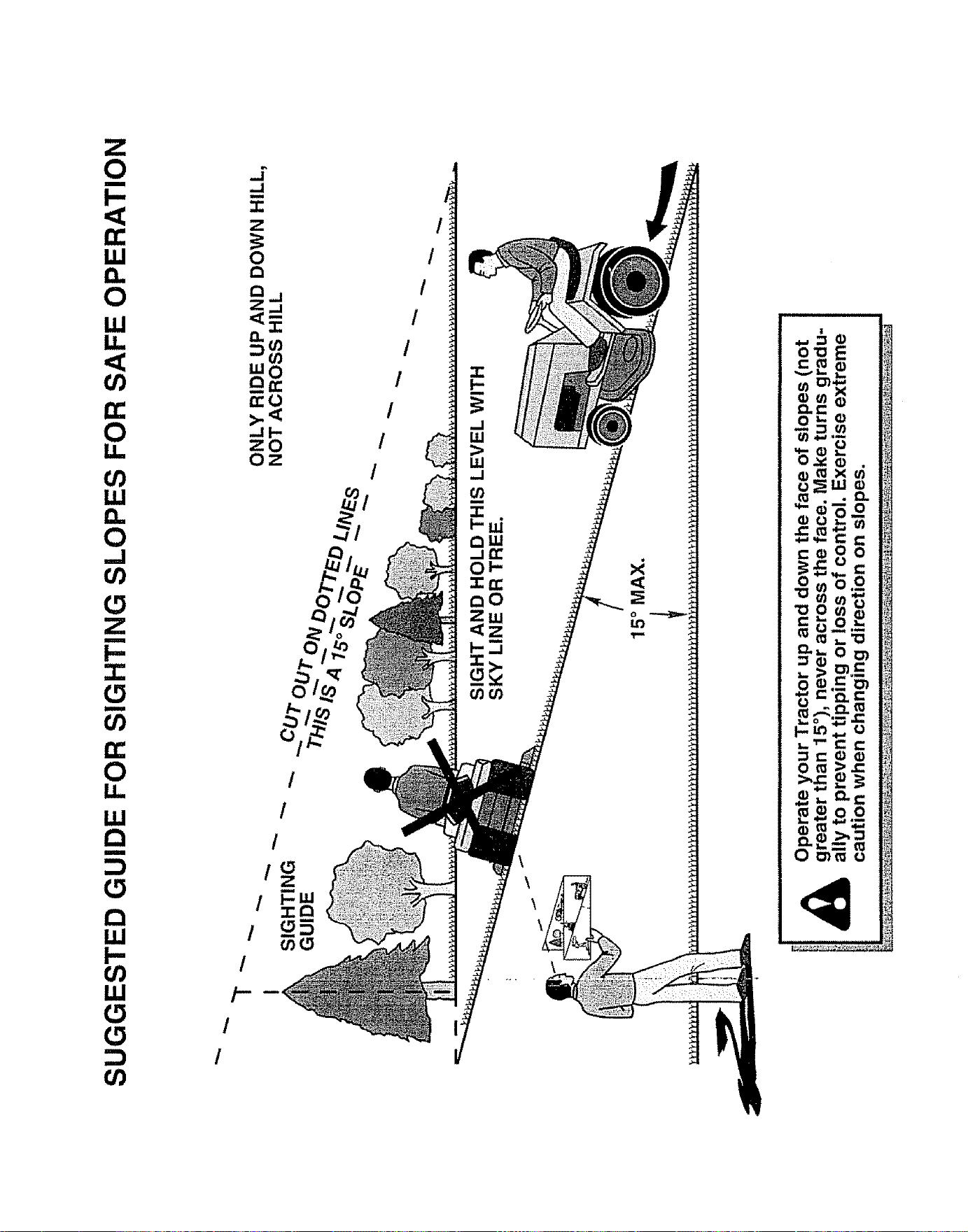
SUGGESTED GUIDE FOR SIGHTING SLOPES FOR SAFE OPERATION
"T
SIGHTING
IIDE
ONLY RIDE UP AND DOWN HILL,
NOT ACROSS HILL
SIGHT AND HOLD THIS LEVEL WITH
SKY LINE OR TREE.
!
15 ° MAX.
OWNER'S
MANUAL
MODEL NO.
917.258861
IF YOU NEED
REPAIR SERVICE
OR PARTS:
FOR REPAIR SERVICE, CALL
THIS TOLL FREE NUMBER:
1-800-4-REPAIR
(1-800-473-7247)
FOR REPLACEMENT PARTS
INFORMATION AND
ORDERING:, CALL THIS
TOLL FREE NUMBER:
1-800-FON-PART
(1-800-366-7278)
FOR CONSUMER ASSISTANCE
HOT LINE, CALL THIS
TOLL FREE NUMBER:
1-800-659-5917
£RRFTSMRN
18.5 HP TWIN CYLINDER
ELECTRIC START
46" MOWER
6 SPEED TRANSAXLE
GARDEN TRACTOR
Each tractor has its own model number. Each engine has
its own model nurnber_
The model number for your tractor will be found on the
model plate located under the seat.
The model number for your engine will be found on the
blower housing of the engine,.
All parts listed herein may be ordered from any Sears,
Roebuck and Co. Service Center/Department and most Re-
tail Stores,
WHEN ORDERING REPAIR PARTS, ALWAYS GIVE THE
FOLLOWING INFORMATION:
- PRODUCT - TRACTOR
,, MODEL NUMBER - 917.258861
. ENGINE MODEL NO. - MV18S-58560
• PART NUMBER
• PART DESCRIPTION
Your Sears merchandise has added value when you
consider Sears has service units nationwide staffed with
Sears trained technicians ..... professional technicians
specifically trained to insure that we meet our' pledge to
you, we service what we selL
161019 6.9.97 RH Printed in U.S_Ao
IIIIIII III IIIIIIIIIIIII1'111111111 .................................................. ,-rr_,t