
Loading ...
Loading ...
Loading ...
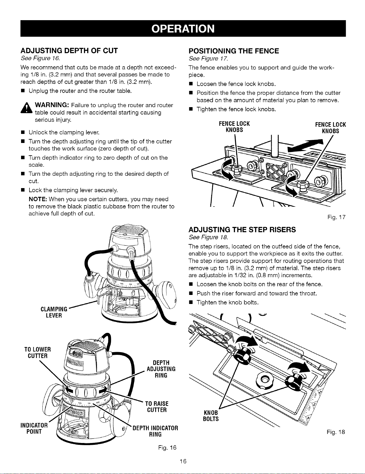
ADJUSTING DEPTH OF CUT
See Figure 16.
We recommend that cuts be made at a depth not exceed-
ing 1/8 in. (3.2 mm) and that several passes be made to
reach depths of cut greater than 1/8 in. (3.2 mm).
• Unplug the router and the router table.
,_ WARNING: Failure to unplug the router and router
table could result in accidental starting causing
serious injury.
• Unlock the clamping lever.
• Turn the depth adjusting ring until the tip of the cutter
touches the work surface (zero depth of cut).
• Turn depth indicator ring to zero depth of cut on the
scale.
• Turn the depth adjusting ring to the desired depth of
cut.
• Lock the clamping lever securely.
NOTE: When you use certain cutters, you may need
to remove the black plastic subbase from the router to
achieve full depth of cut.
CLAMPING
LEVER
POSITIONING THE FENCE
See Figure 17.
The fence enables you to support and guide the work-
piece.
• Loosen the fence lock knobs.
• Position the fence the proper distance from the cutter
based on the amount of material you plan to remove.
• Tighten the fence lock knobs.
FENCELOCK FENCELOCK
KNOBS KNOBS
Fig. 17
ADJUSTING THE STEP RISERS
See Figure 18.
The step risers, located on the outfeed side of the fence,
enable you to support the workpiece as it exits the cutter.
The step risers provide support for routing operations that
remove up to 1/8 in. (3.2 mm) of material. The step risers
are adjustable in 1/32 in. (0.8 mm) increments.
• Loosen the knob bolts on the rear of the fence.
• Push the riser forward and toward the throat.
• Tighten the knob bolts.
TOLOWER
CUTTER
\
/
INDICATOR
POINT
i
Fig. 16
KNOB
BOLTS
Fig. 18
16
Loading ...
Loading ...
Loading ...