Loading ...
Loading ...
Loading ...
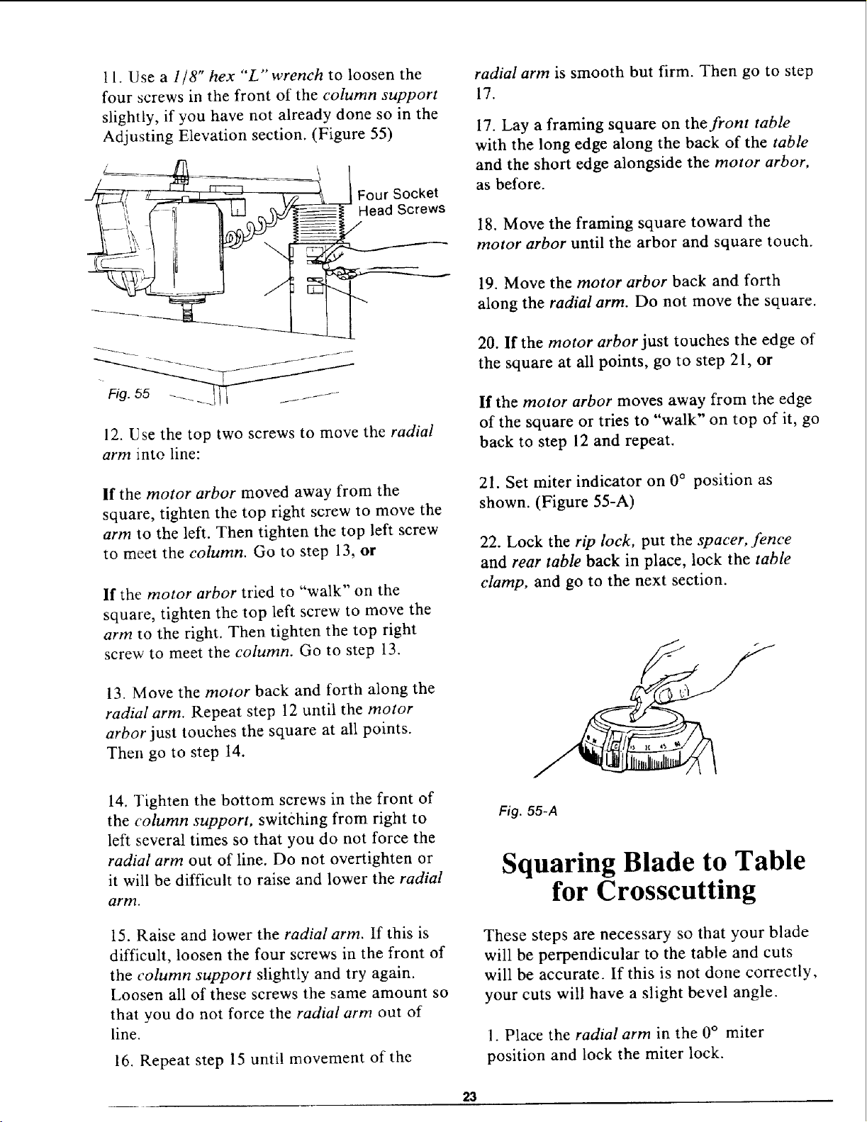
11. Use a 1/8" hex "L" wrench to loosen the
four screws in the front of the column support
slightly, if you have not already done so in the
Adjusting Elevation section. (Figure 55)
Four Socket
Head Screws
J
12. Use the top two screws to move the radial
arm into line:
If the motor arbor moved away from the
square, tighten the top right screw to move the
arm to the left. Then tighten the top left screw
to meet the column. Go to step 13, or
If the motor arbor tried to "walk" on the
square, tighten the top left screw to move the
arm to the right. Then tighten the top right
screw to meet the column. Go to step 13.
13. Move the motor back and forth along the
radial arm. Repeat step 12 until the motor
arbor just touches the square at all points.
Then go to step 14.
14. Tighten the bottom screws in the front of
the column support, switching from right to
left several times so that you do not force the
radial arm out of line. Do not overtighten or
it will be difficult to raise and lower the radial
arm.
15. Raise and lower the radial arm. If this is
difficult, loosen the four screws in the front of
the column support slightly and try again.
Loosen all of these screws the same amount so
that you do not force the radial arm out of
line.
16. Repeat step 15 until movement of the
radial arm is smooth but firm. Then go to step
17.
17. Lay a framing square on the front table
with the long edge along the back of the table
and the short edge alongside the motor arbor,
as before.
18. Move the framing square toward the
motor arbor until the arbor and square touch.
19. Move the motor arbor back and forth
along the radial arm. Do not move the square.
20. If the motor arbor just touches the edge of
the square at all points, go to step 21, or
If the motor arbor moves away from the edge
of the square or tries to "walk" on top of it, go
back to step 12 and repeat.
21. Set miter indicator on 0 ° position as
shown. (Figure 55-A)
22. Lock the rip lock, put the spacer, fence
and rear table back in place, lock the table
clamp, and go to the next section.
Fig. 55-A
Squaring Blade to Table
for Crosscutting
These steps are necessary so that your blade
will be perpendicular to the table and cuts
will be accurate. If this is not done correctly,
your cuts will have a slight bevel angle.
I. Place the radial arm in the 0 ° miter
position and lock the miter lock.
23
Loading ...
Loading ...
Loading ...