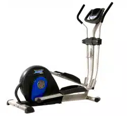
ModetNo.831.28544.2
SerialNo.
Serial
Number
Decal\\
- Assembly
- Operation
- Maintenance
- Part List and Drawing
Read all precautions and instruc-
tions in this manual before using
this equipment. Keep this msnu-
sJ for future reference.
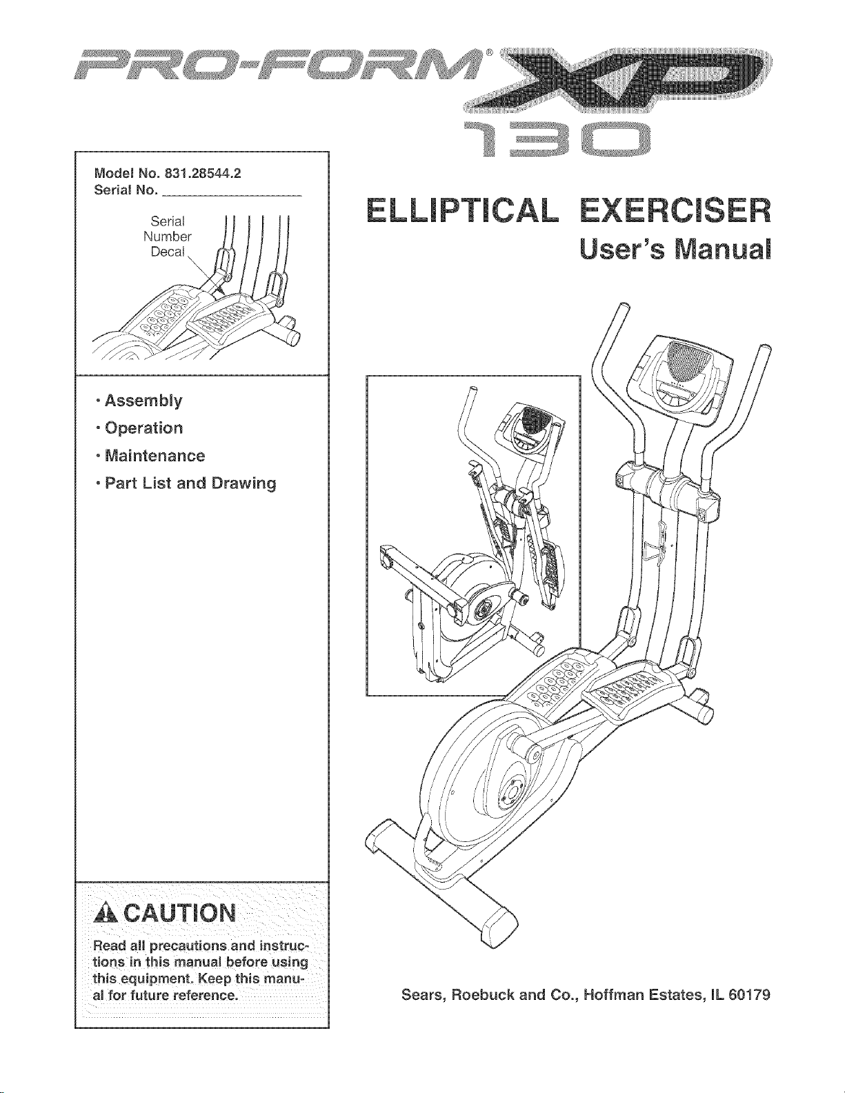
User's Manuam
Sears, Roebuck and Co., Hoffman Estates, mL60179
TABLE OF CONTENTS
IMPORTANT PRECAUTIONS ................................................................ 3
BEFORE YOU BEGIN ...................................................................... 4
ASSEMBLY ............................................................................... 5
HOW TO USE THE ELLIPTICAL EXERCISER .................................................. 10
MAINTENANCE AND TROUBLESHOOTING ................................................... 23
CONDITIONING GUIDELINES ............................................................... 24
PART LIST .............................................................................. 25
EXPLODED DRAWING .................................................................... 26
HOW TO ORDER REPLACEMENT PARTS ............................................. Back Cover
90 DAY FULL WARRANTY .......................................................... Back Cover
2
m __ __
iMPORTANT PRECAUTmONS
WARNING: Toreducether skofse.ousinjury,readthefo.owiogimportantpreeau-
tions before using the elliptical exerciser,
1. Read all instructions in this manual and all 10, The pulse sensor is not a medieaJ device.
warnings on the elliptical exerciser before Various factors may affect the accuracy of
using the elliptical exerciser. Use the eHipti- hear_ rate readings. The pulse sensor is
cal exercise OnJy as described in this intended onJy as an exercise aid in determin-
manual, ing heart rate trends in general
2. it is the responsibility of the owner to ensure
that aH users of the elliptical exerciser are
adequatemy informed of aH precautions.
3.
11. Keep your back straight when using the eHip=
tical exerciser; do not arch your back.
12. ff you feel pain or dizziness while exercising,
The elliptical exerciser is intended for stop immediately and cool down.
home use only. Do not use the elliptical
exerciser in a commercial rental or institu_ 13. When you stop exercising, show the pedals
tional setting, to slowly come to a stop.
4.
from moisture and dust. Place the elliptical
exerciser on a tevel surface, with a mat
beneath it to protect the floor or carpet.
Make sure that there is enough clearance
around the elliptical exerciser to mount, dis-
mount, and use it.
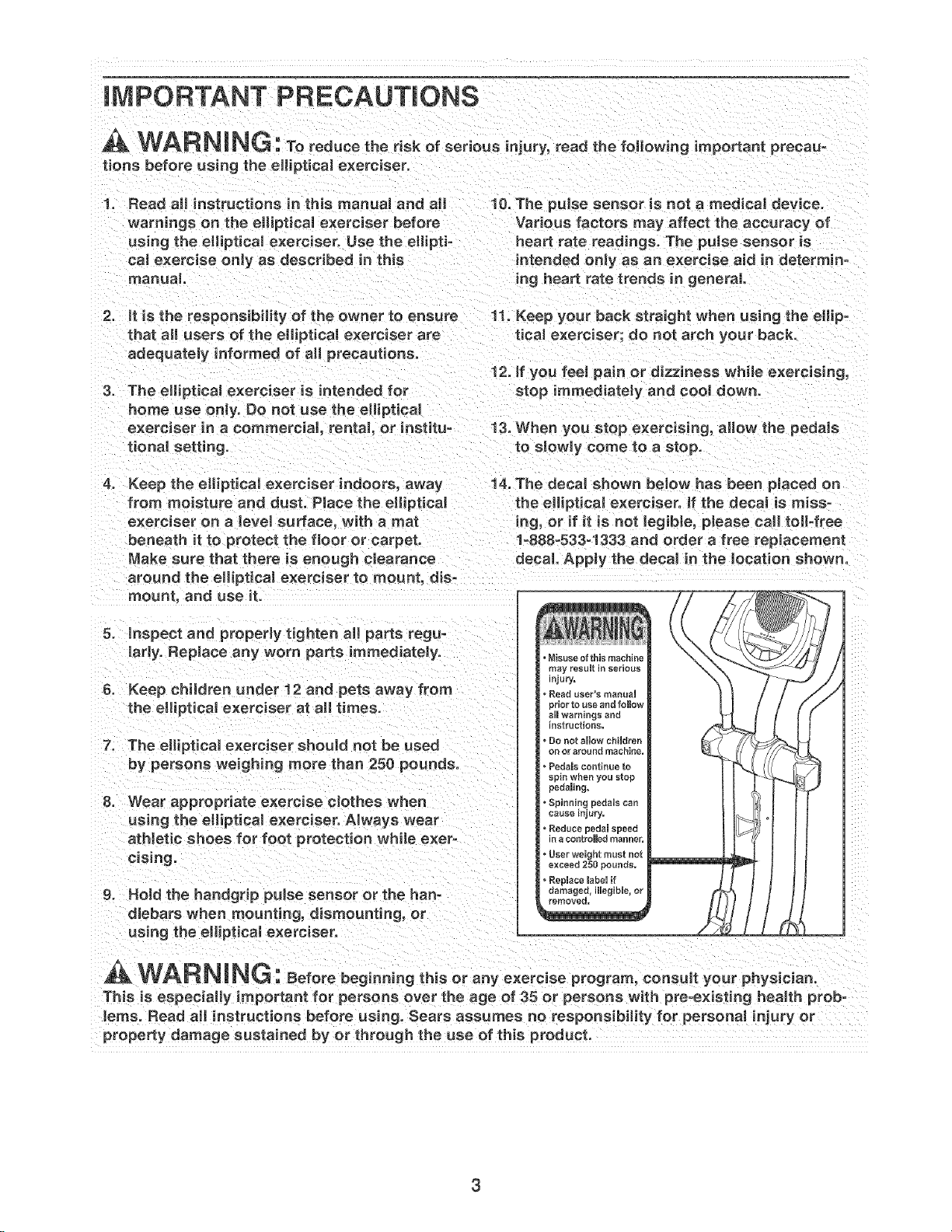
Keep the eHipticaJ exerciser indoors, away 14. The decal shown below has been pJaced on
the elliptical exerciser. If the decal is miss-
ing, or if it is not Jegible, please call toll°free
1o888-533-1333 and order a free replacement
decal. Apply the decal in the location shown.
5. inspect and properly tighten aH parts regu=
larly. Replace any worn parts immediately.
6. Keep children under 12 and pets away from
the elliptical exerciser at all times.
7. The elliptical exerciser should not be used
by persons weighing more than 250 pounds.
8. Wear appropriate exercise eJothes when
using the eHipticaJ exerciser. Always wear
at Netic shoes for foot protection while exer-
cising.
g. Hold the handgrip puJse sensor or the han-
dlebars when mounting, dismounting, or
using the elliptical exerciser.
, Misuse of this machine
may result in serious
n]ury.
Resd uee_"s maeual
_dor to use and follow
aHIwarnings and
nstructioRs.
• De net show chiUdren
on or around machine,
Pedamscontinue to
spin when you stop
pedaming,
Spinning pedsHs can
cause injury.
• Reduce pedam speed
n a sontroHed manner,
• User weight must not
exceed 250 pounds,
• Replace mabeHif
oamagee, illegible, or
_emoved=
WAR N NG: eforebeginningth soranye,orc seprogram,consultyourphysician.
This is especially important for persons over the age of 35 or persons with pre-existing hea_th prob-
lems. Read aH instructions before using. Sears assumes no responsibility for persona_ injury or
property damage sustained by or through the use of this product.
BEFORE YOU BEGmN
Thank you for selecting the revolutionary PROFORM _'
XP 130 elliptical exerciser. The XP 130 elliptical exer-
ciser provides a wide array of features designed to
make your workouts at home more effective and
enjoyable--and when you're not exercising, the
unique XP 130 can be folded out of the away.
For your benefit, read this manual carefully before
you use the elliptical exerciser. If you have ques-
tions after reading this manual, call 1-800-4-MY-
HOME <'(1-800-469-4663). To help us assist you,
please note the product model number and serial
number before calling. The model number is
831.28544.2. The serial number can be found on a
decal attached to the elliptical exerciser (see the front
cover of this manual for the location of the decal).
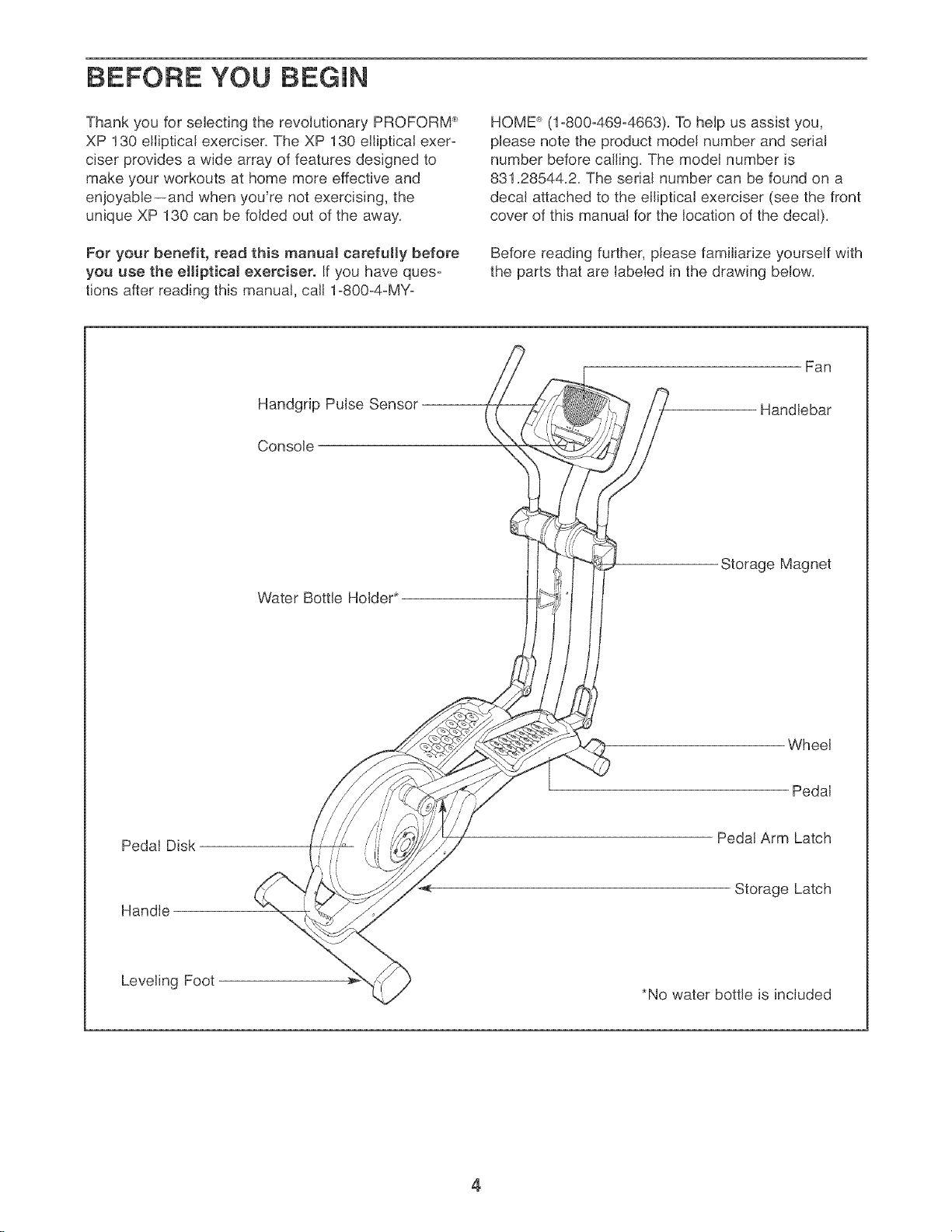
Before reading further, please familiarize yourself with
the parts that are labeled in the drawing below.
Handgrip Pulse Sensor
Console
Fan
Handlebar
Water Bottle Holder*
Storage Magnet
Wheel
Pedal
Pedal Disk
Handle
Pedal Arm Latch
Storage Latch
Leveling Foot
*No water bottle is included
4
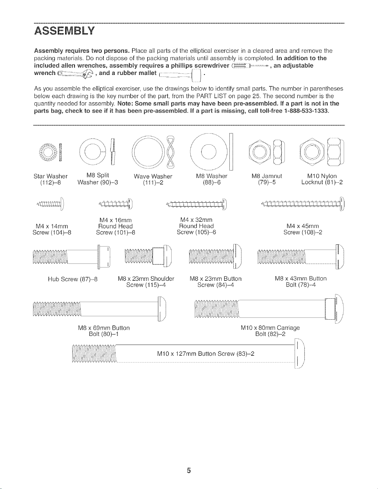
AssembJy requires two persons. PJace aJlparts of the eJlipticaJ exerciser in a cleared area and remove the
packing materials. Do not dispose of the packing materials untiJ assembly is completed. In addition to the
included alien wrenches, assembty requires a phillips screwdriver (_:l ..... , an adjustable
wrench , and a rubber mallet C:C _:: :c( ) "
As you assemble the eJliptical exerciser, use the drawings below to identify small parts. The number in parentheses
below each drawing is the key number of the part, from the PART LIST on page 25. The second number is the
quantity needed for assembly. Note: Some small parts may have been pre-assembled. If a part is not in the
parts bag, check to see if it has been pre=assembled, tf a part is missing, calJ toll=free 1=888=533=1333.
Star Washer
(112)-8
M8 Split
Washer (90)-3
Wave Washer M8 Washer M8 Jamnut M10 Nylon
(111)-2 (88)-6 (79)-5 Locknut (81)-2
M4 x 14mm
Screw (104)-8
M4 x 16mm
Round Head
Screw (101 )-8
Hub Screw (87)-8
M8 x 23mm Shoulder
Screw (115)-4
M8 x 69mm Button
Bolt (80)-1
M4 x 32mm
Round Head
Screw (105)-6
M8 x 23mm Button
Screw (84)-4
M4 x 45mm
Screw (108)-2
M8 x 43mm Button
Bolt (78)-4
M10 x 80mm Carriage
Bolt (82)-2
M10 x 127mm Button Screw (83)-2
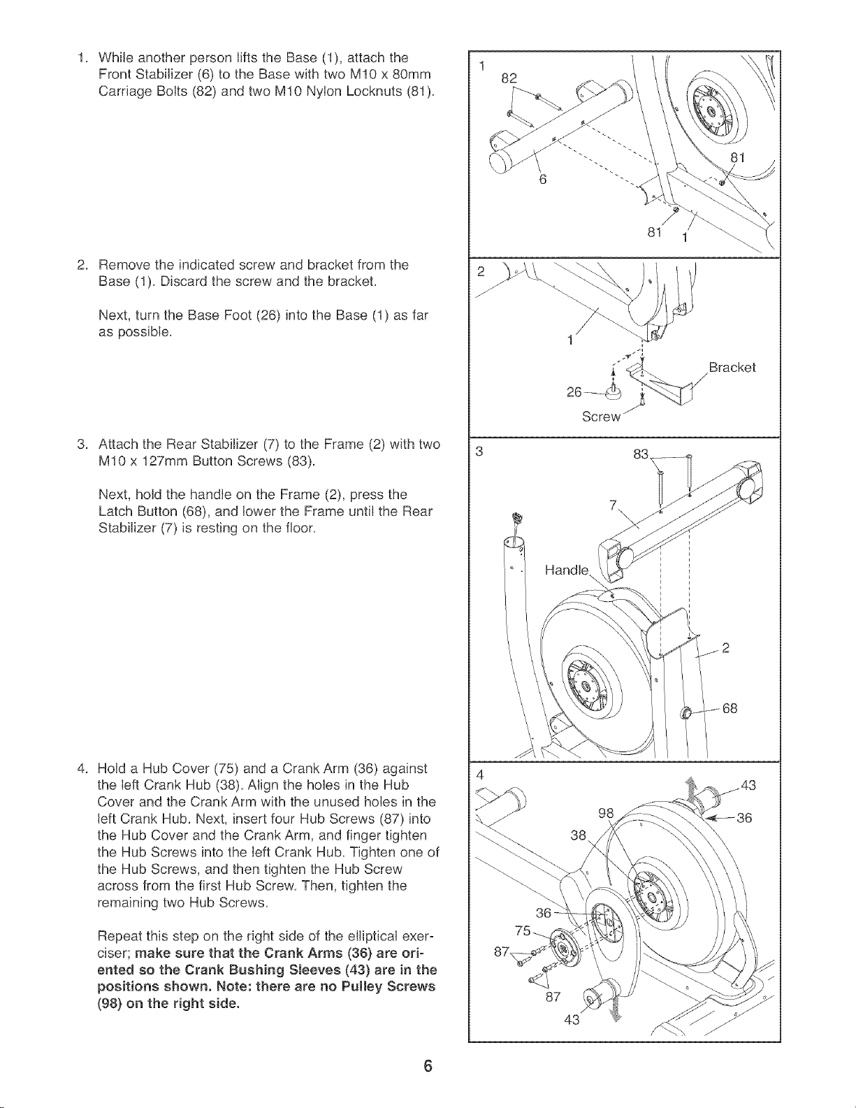
WhileanotherpersonliftstheBase(1),attachthe
FrontStabilizer(6)totheBasewithtwoM10x80mm
CarriageBolts(82)andtwoM10NylonLocknuts(81),
Removetheindicatedscrewandbracketfromthe
Base(1),Discardthescrewandthebracket,
Next,turntheBaseFoot(26)intotheBase(1)asfar
aspossible,
AttachtheRearStabilizer(7)totheFrame(2)withtwo
M10x127mmButtonScrews(83),
Next,holdthehandleontheFrame(2),pressthe
LatchButton(68),andlowertheFrameuntiltheRear
Stabilizer(7)isrestingonthefloor,
HoldaHubCover(75)andaCrankArm(36)against
theleftCrankHub(38),AligntheholesintheHub
CoverandtheCrankArmwiththeunusedholesinthe
leftCrankHub,Next,insertfourHubScrews(87)into
theHubCoverandtheCrankArm,andfingertighten
theHubScrewsintotheleftCrankHub,Tightenoneof
theHubScrews,andthentightentheHubScrew
acrossfromthefirstHubScrew,Then,tightenthe
remainingtwoHubScrews,
Repeatthisstepontherightsideoftheellipticalexero
ciser;makesurethattheCrankArms(36)areori-
entedsotheCrankBushingSleeves(43)areinthe
positionsshown.Note:therearenoPulleyScrews
(98}ontherightside.
1
82
6
81 1
Screw
Bracket
7\
38
98
36
87
43
6
5. 5
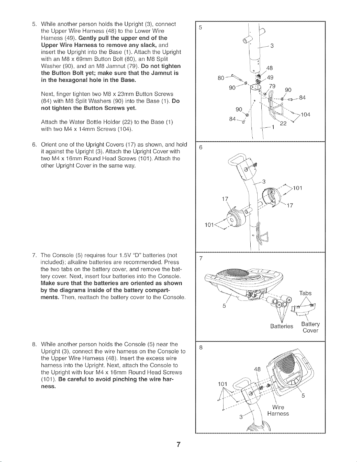
While another person holds the Upright (3), connect
the Upper Wire Harness (48) to the Lower Wire
Harness (49). Gently pull the upper end of the
Upper Wire Harness to remove any sJack, and
insert the Upright into the Base (1). Attach the Upright
with an M8 x 69mm Button Bolt (80), an M8 Split
Washer (90), and an M8 Jamnut (79). So not tighten
the Button Bolt yet; make sure that the Jamnut is
in the he×agonal hole in the Base.
Next, finger tighten two M8 x 23mm Button Screws
(84) with M8 Split Washers (90) into the Base (1). Bo
not tighten the Button Screws yet.
Attach the Water Bottle Holder (22) to the Base (1)
with two M4 x 14mm Screws (104).
Orient one of the Upright Covers (17) as shown, and hold
it against the Upright (3). Attach the Upright Cover with
two M4 x 16mm Round Head Screws (101). Attach the
other Upright Cover in the same way.
The Console (5) requires four 1.5V "D" batteries (not
included); alkaline batteries are recommended. Press
the two tabs on the battery cover, and remove the bat-
tery cover. Next, insert four batteries into the Console.
Make sure that the batteries are oriented as shown
by the diagrams inside of the battery compart-
ments. Then, reattach the battery cover to the Console.
While another person holds the Console (5) near the
Upright (3), connect the wire harness on the Console to
the Upper Wire Harness (48). Insert the excess wire
harness into the Upright. Next, attach the Console to
the Upright with four M4 x 16mm Round Head Screws
(101). Be careful to avoid pinching the wire har-
ness.
48
_49
79
9O
17
Batteries Battery
Cover
48
101
Wire
Harness
7
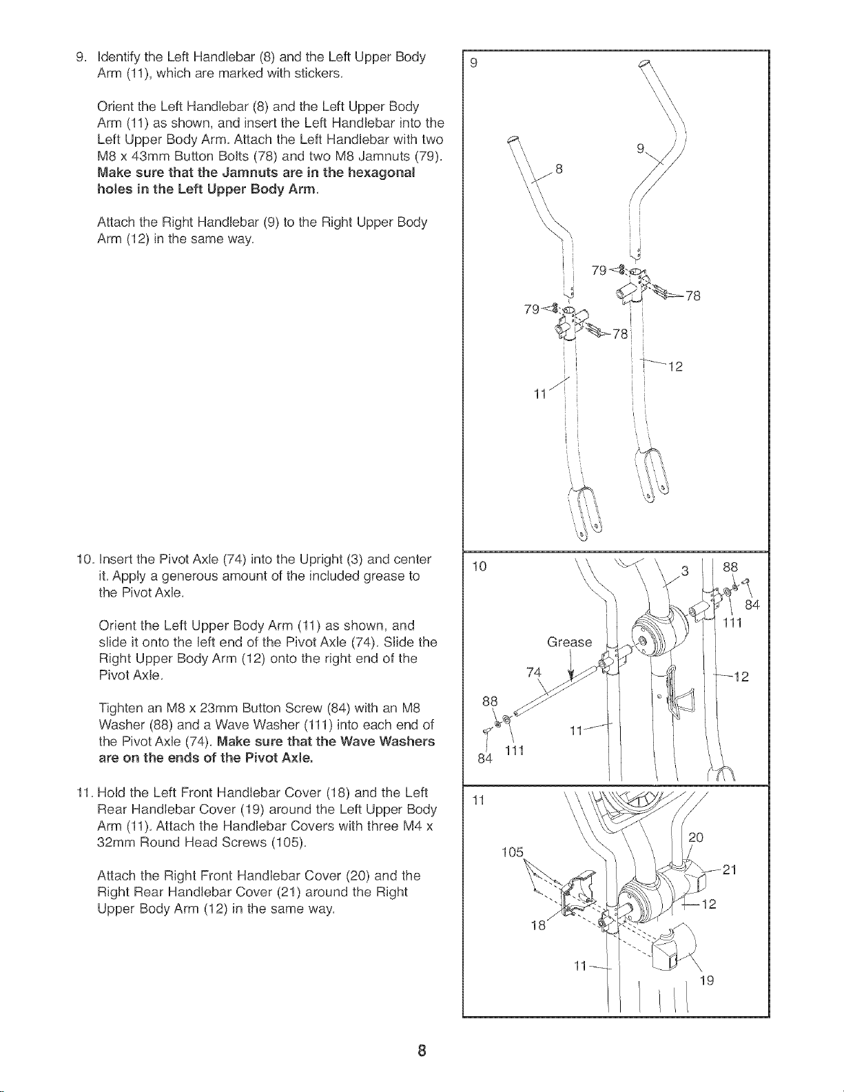
Identify the Left Handlebar (8) and the Left Upper Body
Arm (11), which are marked with stickers,
Orient the Left Handlebar (8) and the Left Upper Body
Arm (11) as shown, and insert the Left Handlebar into the
Left Upper Body Arm, Attach the Left Handlebar with two
M8 x 43mm Button Bolts (78) and two M8 Jamnuts (79),
Make sure that the Jamnuts are in the hexagonal
hoJes in the Left Upper Body Arm,
Attach the Right Handlebar (9) to the Right Upper Body
Arm (12) in the same way,
10, Insert the Pivot Axle (74) into the Upright (3) and center
it, Apply a generous amount of the included grease to
the Pivot Axle,
Orient the Left Upper Body Arm (11) as shown, and
slide it onto the left end of the Pivot Axle (74), Slide the
Right Upper Body Arm (12) onto the right end of the
Pivot Axle,
Tighten an M8 x 23mm Button Screw (84) with an M8
Washer (88) and a Wave Washer (111) into each end of
the Pivot AxJe (74), Make sure that the Wave Washers
are on the ends of the Pivot A×teo
11, Hold the Left Front Handlebar Cover (18) and the Left
Rear Handlebar Cover (19) around the Left Upper Body
Arm (11), Attach the Handlebar Covers with three M4 x
32ram Round Head Screws (105),
Attach the Right Front Handlebar Cover (20) and the
Right Rear Handlebar Cover (21) around the Right
Upper Body Arm (12) in the same way,
10
88
11
' j
[ ,
11_ ii
L i
74
\
111
105
Grease
18
11
/
i¸ /
i
i
i
ii
i
J
i
I '
88
_/ 84
111
/
2o
19
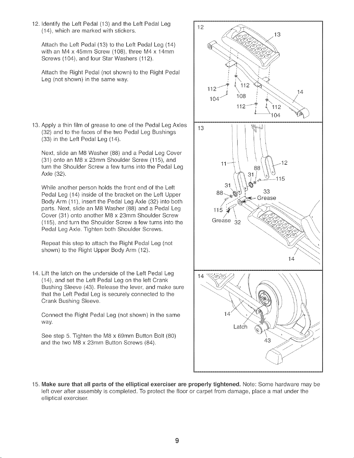
12.IdentifytheLeftPedal(13)andtheLeftPedalLeg
(14),whicharemarkedwithstickers.
AttachtheLeftPedal(13)totheLeftPedalLeg(14)
withanM4x45mmScrew(108),threeM4x 14mm
Screws(104),andfourStarWashers(112).
AttachtheRightPedal(notshown)totheRightPedal
Leg(notshown)inthesameway.
13.ApplyathinfilmofgreasetooneofthePedalLegAxles
(32)andtothefacesofthetwoPedalLegBushings
(33)intheLeftPedalLeg(14).
Next,slideanM8Washer(88)andaPedalLegCover
(31)ontoanM8x23mmShoulderScrew(115),and
turntheShoulderScrewafewturnsintothePedalLeg
Axle(32),
WhileanotherpersonholdsthefrontendoftheLeft
PedalLeg(14)insideofthebracketontheLeftUpper
BodyArm(11),insertthePedalLegAxle(32)intoboth
parts.Next,slideanM8Washer(88)andaPedalLeg
Cover(31)ontoanotherM8x23mmShoulderScrew
(115),andturntheShoulderScrewafewturnsintothe
PedalLegAxle.TightenbothShoulderScrews.
RepeatthissteptoattachtheRightPedalLeg(not
shown)totheRightUpperBodyArm(12).
14.LiftthelatchontheundersideoftheLeftPedalLeg
(14),andsettheLeftPedalLegontheleftCrank
BushingSleeve(43).Releasethelever,andmakesure
thattheLeftPedalLegissecurelyconnectedtothe
CrankBushingSleeve.
ConnecttheRightPedalLeg(notshown)inthesame
way.
Seestep5_TightentheM8x69mmButtonBolt(80)
andthetwoM8x23mmButtonScrews(84),
12
13
13
108
112J
104
31
33
Grease
115
Grease 32
14
Latch
43
14
15. Make sure that all parts of the eliiptieaJ exerciser are properly tightened. Note: Some hardware may be
left over after assembly is completed. To protect the floor or carpet from damage, place a mat under the
elliptical exerciser.
9
HOW TO USE THE ELLIPTICAL EXERCISER
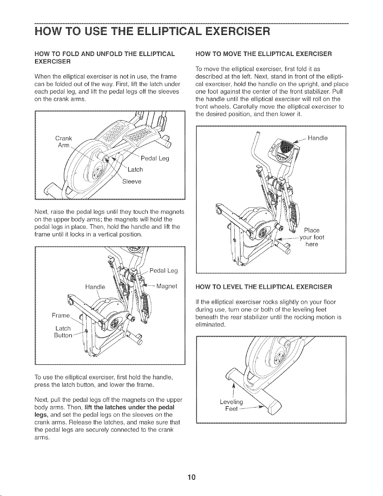
HOW TO FOLD AND UNFOLD THE ELLIPTICAL
EXERCISER
When the ellipticaJ exerciser is not in use, the frame
can be folded out of the way, First, lift the latch under
each pedal leg, and lift the pedal legs off the sleeves
on the crank arms,
Crank
Arm
Pedal Leg
" Latch
Sleeve
Next, raise the pedal legs until they touch the magnets
on the upper body arms; the magnets will hold the
pedal Jegs in pJace, Then, hold the handle and lift the
frame until it locks in a verticaJ position,
Handle
Pedal Leg
Frame.
Latch
Butt(
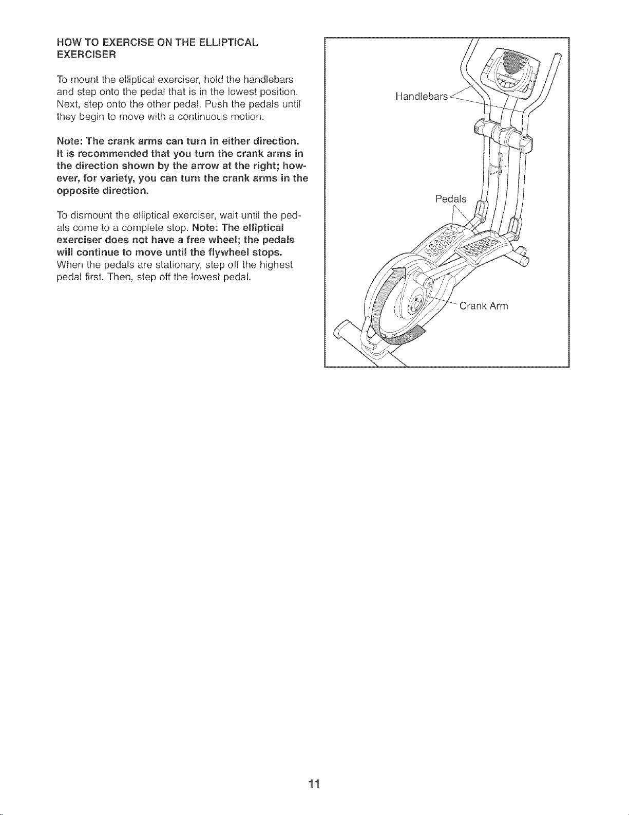
HOW TO MOVE THE ELLIPTICAL EXERCISER
To move the elliptical exerciser, first fold it as
described at the left, Next, stand in front of the elliptic
cal exerciser, hold the handle on the upright, and place
one foot against the center of the front stabilizer, Pull
the handJe untiJ the eiiipticaJ exerciser wiJJroJJon the
front wheels, Carefully move the elliptical exerciser to
the desired position, and then lower it,
j Handle
PJace
here
HOW TO LEVEL THE ELUPTJCAL EXERCISER
If the elliptical exerciser rocks slightly on your floor
during use, turn one or both of the JeveJingfeet
beneath the rear stabilizer untiJ the rocking motion is
eliminated,
To use the elliptical exerciser, first hold the handle,
press the latch button, and lower the frame,
Next, pulJthe pedal legs off the magnets on the upper
body arms, Then, lift the Jatches under the pedaJ
Jegs, and set the pedaJ legs on the sleeves on the
crank arms Release the latches, and make sure that
the pedaJ legs are securely connected to the crank
arms,
Leveling
I0
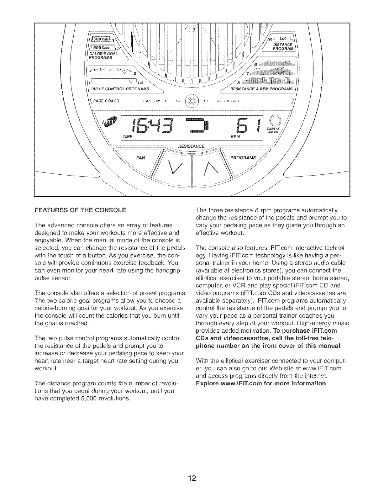
HOW TO EXERCISE ON THE ELLIPTICAL
EXERCISER
To mount the elliptical exerciser, hold the handlebars
and step onto the pedal that is in the lowest position.
Next, step onto the other pedal. Push the pedals until
they begin to move with a continuous motion.
Note: The crank arms can turn in either direction.
tt is recommended that you turn the crank arms in
the direction shown by the arrow at the right; how-
ever, for variety, you can turn the crank arms in the
opposite direction.
To dismount the elliptical exerciser, wait until the ped-
als come to a complete stop. Note: The ellipticaJ
exerciser does not have a free wheek the pedaJs
witl continue to move until the flywheel stops.
When the pedals are stationary, step off the highest
pedal first. Then, step off the lowest pedal.
Handlebars
Pedals
11
CALORIE GOAL
PROGRAMS
FAN PROGRAMS
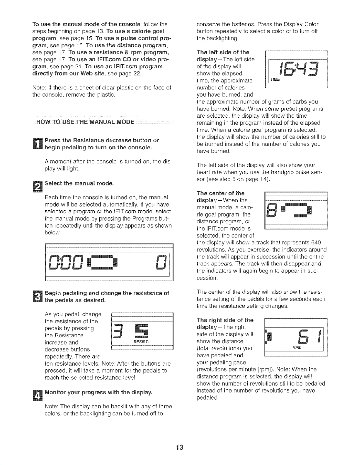
FEATURES OF THE CONSOLE
The advanced console offers an array of features
designed to make your workouts more effective and
enjoyable. When the manual mode of the console is
selected, you can change the resistance of the pedals
with the touch of a button. As you exercise, the con-
sole will provide continuous exercise feedback. You
can even monitor your heart rate using the handgrip
pulse sensor.
The console also offers a selection of preset programs.
The two calorie goal programs allow you to choose a
calorie-burning goal for your workout. As you exercise,
the console will count the calories that you burn until
the goal is reached.
The two pulse control programs automatically control
the resistance of the pedals and prompt you to
increase or decrease your pedaling pace to keep your
heart rate near a target heart rate setting during your
workout.
The distance program counts the number of revolu-
tions that you pedal during your workout, until you
have completed 5,000 revolutions.
The three resistance & rpm programs automatically
change the resistance of the pedals and prompt you to
vary your pedaling pace as they guide you through an
effective workout.
The console also features iFIT.com interactive technol-
ogy. Having iFIT.com technology is like having a per-
sonal trainer in your home. Using a stereo audio cable
(available at electronics stores), you can connect the
elliptical exerciser to your portable stereo, home stereo,
computer, or VCR and play special iFIT.com CD and
video programs (iFIT.com CDs and videocassettes are
available separately), iFIT.com programs automatically
control the resistance of the pedals and prompt you to
vary your pace as a personal trainer coaches you
through every step of your workout. High-energy music
provides added motivation. To purchase iFIT.com
CDs and videocassettes, calJ the toll-free tele-
phone number on the front cover of this manual.
With the elliptical exerciser connected to your comput-
er, you can also go to our Web site at wwwJFIT.com
and access programs directly from the intemet.
Explore wwwJFIT.com for more information.
12
To use the manual mode of the console, follow the
steps beginning on page 13. To use a calorie goal
program, see page 15. To use a pulse control pro-
gram, see page 15. To use the distance program,
see page 17. To use a resistance & rpm program,
see page 17. To use an iFIT.com CD or video pro-
gram, see page 21. To use an iFIT.com program
directly from our Web site, see page 22.
Note: If there is a sheet of clear plastic on the face of
the console, remove the plastic.
HOW TO USE THE MANUAL MODE
Press the Resistance decrease button or
begin pedaling to turn on the console.
A moment after the console is turned on, the dis-
play will light.
Select the manual mode.
Each time the console is turned on, the manual
mode will be selected automatically. If you have
selected a program or the iFIT.com mode, select
the manual mode by pressing the Programs but-
ton repeatedly until the display appears as shown
below.
, .._o O1
Begin pedaling and change the resistance of
the pedals as desiredo
As you pedal, change
the resistance of the
pedals by pressing
the Resistance
increase and
decrease buttons
repeatedly. There are
ten resistance levels. Note: After the buttons are
pressed, it will take a moment for the pedals to
reach the selected resistance level.
Monitor your progress with the display.
Note: The display can be backlit with any of three
colors, or the backlighting can be turned off to
conserve the batteries. Press the Display Color
button repeatedly to select a color or to turn off
the backlighting.
The left side of the
display--The left side
of the display will
show the elapsed
time, the approximate T_ME
number of calories
you have burned, and
the approximate number of grams of carbs you
have burned. Note: When some preset programs
are selected, the display will show the time
remaining in the program instead of the elapsed
time. When a calorie goal program is selected,
the display will show the number of calories still to
be burned instead of the number of calories you
have burned.
The left side of the display will also show your
heart rate when you use the handgrip pulse sen-
sor (see step 5 on page 14).
The center of the
display--When the
manual mode, a calo-
rie goal program, the
distance program, or
the iFIT.com mode is
selected, the center of
the display will show a track that represents 640
revolutions. As you exercise, the indicators around
the track will appear in succession until the entire
track appears. The track will then disappear and
the indicators will again begin to appear in suc-
cession.
The center of the display will also show the resis-
tance setting of the pedals for a few seconds each
time the resistance setting changes.
The right aide of the H
display--The right
L
side of the display will
show the distance W
(total revolutions) you RPM
have pedaled and
your pedaling pace
(revolutions per minute [rpm]). Note: When the
distance program is selected, the display will
show the number of revolutions still to be pedaled
instead of the number of revolutions you have
pedaled.
13
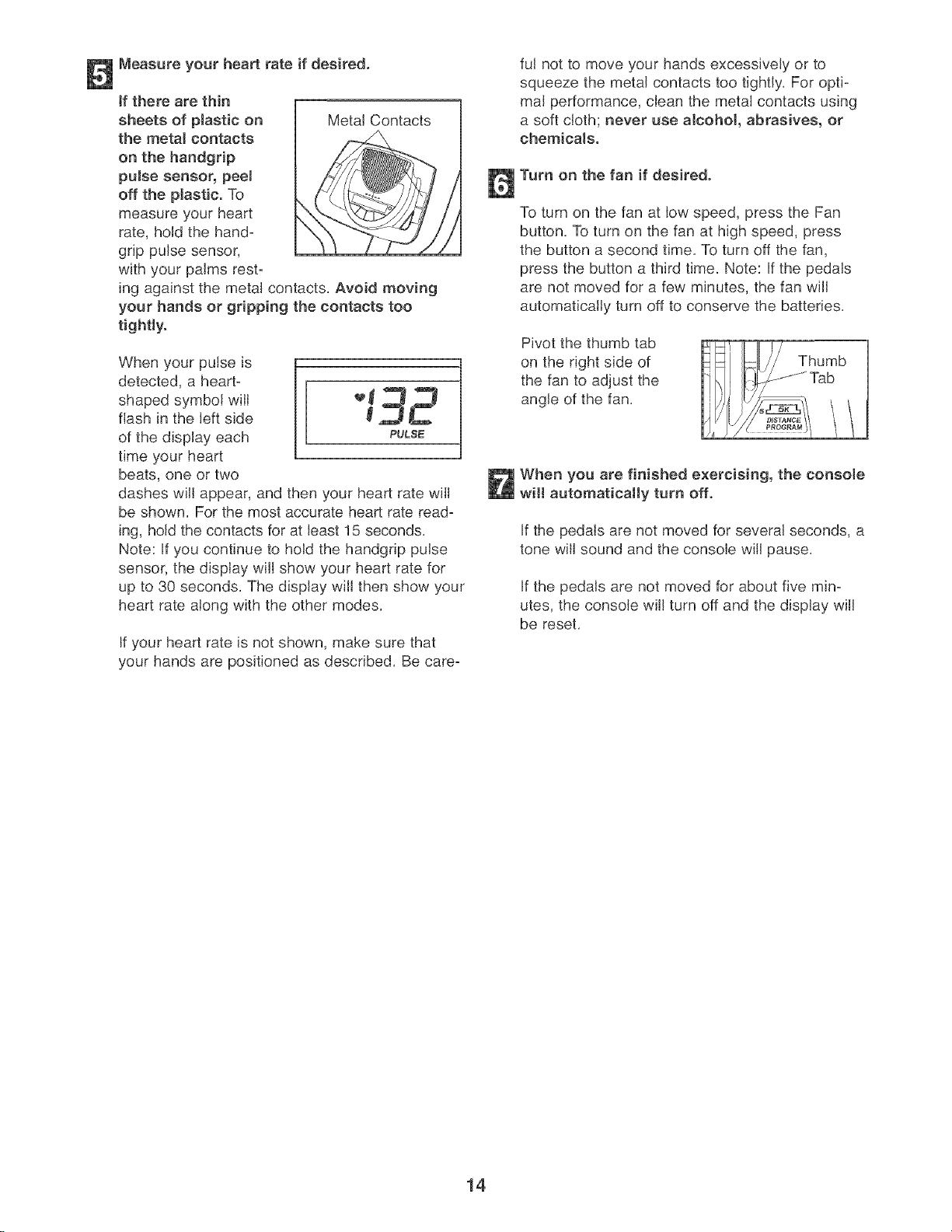
Measure your heart rate if desired.
tf there are thin [
sheets of plastic on / Metal Contacts
the metal contacts
on the handgrip
pulse sensor, peeJ
off the plastic. To
measure your heart
rate, hold the hand-
grip pulse sensor,
with your palms rest-
ing against the metal contacts. Avoid moving
your hands or gripping the contacts too
tightly.
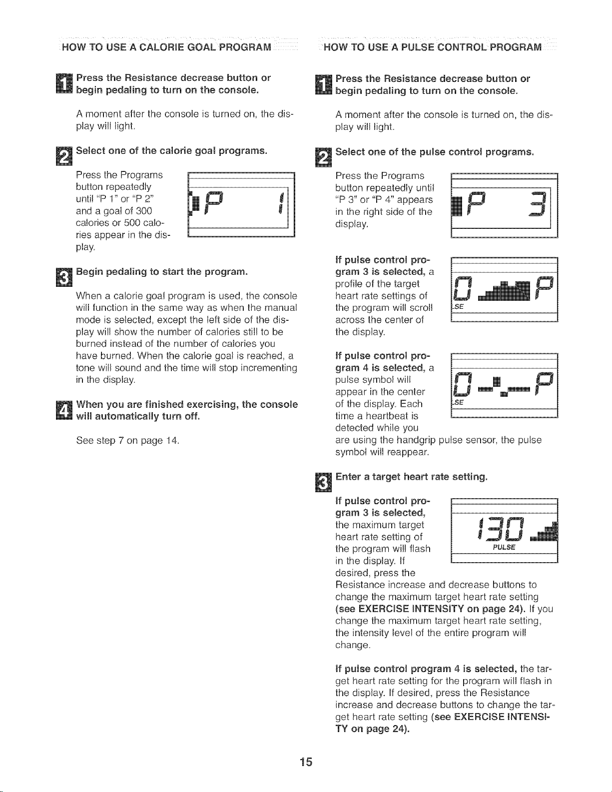
When your pulse is
detected, a heart=
shaped symbol will _ _
flash in the left side _ ,_
of the display each PULSE
time your heart
beats, one or two
dashes will appear, and then your heart rate will
be shown. For the most accurate heart rate read-
ing, hold the contacts for at least 15 seconds.
Note: If you continue to hold the handgdp pulse
sensor, the display will show your heart rate for
up to 30 seconds. The display will then show your
heart rate along with the other modes.
If your heart rate is not shown, make sure that
your hands are positioned as described. Be care-
ful not to move your hands excessively or to
squeeze the metal contacts too tightly. For opti-
mal performance, clean the metal contacts using
a soft cloth; never use a!cohol, abrasives, or
chemicals.
Turn on the fan if desired.
To turn on the fan at low speed, press the Fan
button, To turn on the fan at high speed, press
the button a second time. To turn off the fan,
press the button a third time. Note: If the pedals
are not moved for a few minutes, the fan will
automatically turn off to conserve the batteries.
Pivot the thumb tab
on the right side of
the fan to adjust the
angle of the fan.
Thumb
Tab
When you are finished exercising, the consote
will automatically turn off.
If the pedals are not moved for several seconds, a
tone will sound and the console will pause.
If the pedals are not moved for about five min-
utes, the console will turn off and the display will
be reset.
14
HOW TO USE A CALORIE GOAL PROGRAM HOW TO USE A PULSE CONTROL PROGRAM
Press the Resistance decrease button or
begin pedaJing to turn on the console.
A moment after the console is turned on, the dis-
play will light,
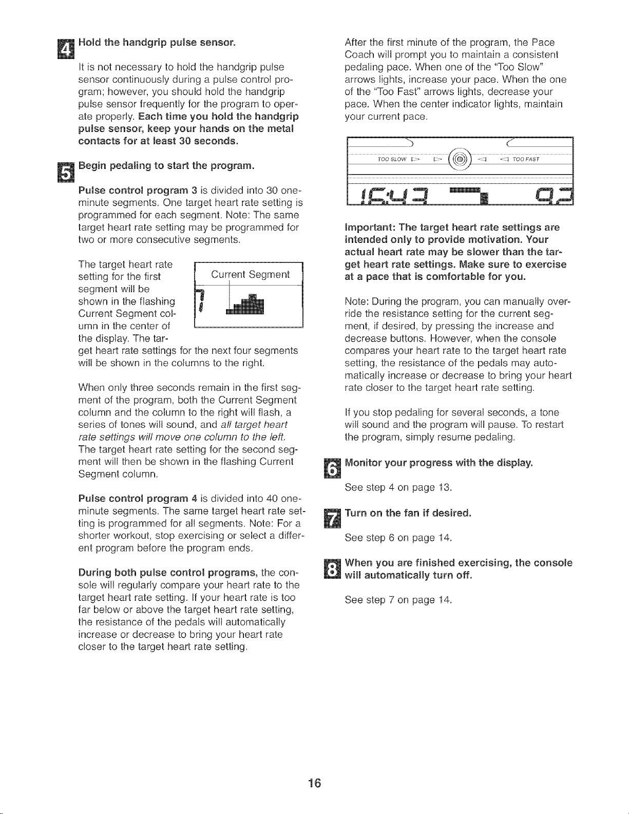
Select one of the calorie goal programs.
sstho
button repeatedly
until "P 1" or "P 2"
and a goal of 300
calories or 500 calo-
ries appear in the dis-
play,
Begin pedaling to start the program.
When a calorie goal program is used, the console
will function in the same way as when the manual
mode is selected, except the left side of the dis-
play will show the number of calories still to be
burned instead of the number of calories you
have burned, When the calorie goal is reached, a
tone will sound and the time will stop incrementing
in the display,
When you are finished exercising, the consoJe
will automatically turn off.
See step 7 on page 14.
Press the Resistance decrease button or
pedaling to turn on the console.
A moment after the console is turned on, the dis-
play will light,
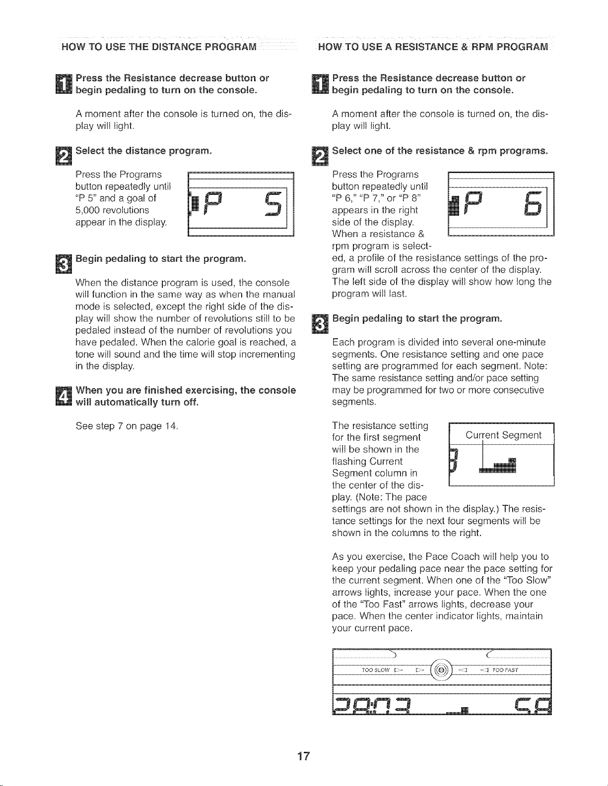
Select one of the pulse control programs.
Press the Programs
button repeatedly until
"P 3" or "P 4" appears
in the right side of the
display,
if puJse control pro-
gram 3 is selected, a
profile of the target
heart rate settings of
the program will scroll
across the center of
the display,
,fpu, econ,ro pro-
gram 4 is selected, a
pulse symbol will
appear in the center m m'm'm'm
of the display, Each
time a heartbeat is
detected while you
are using the handgrip pulse sensor, the pulse
symbol will reappear,
Enter a target heart rate setting.
ff puJse control pro-
gram 3 is seJected,
the maximum target _ _ _"_
heart rate setting of _ ._ L_
the program will flash PULS_
in the display, If
desired, press the
Resistance increase and decrease buttons to
change the maximum target heart rate setting
(see EXERCISE INTENSITY on page 24}. If you
change the maximum target heart rate setting,
the intensity level of the entire program will
change,
ff pulse control program 4 is seJected, the tar-
get heart rate setting for the program will flash in
the display, If desired, press the Resistance
increase and decrease buttons to change the tar-
get heart rate setting (see EXERCISE INTENSI-
TY on page 24).
15
Hotd the handgrip pulse sensor.
it is not necessary to hold the handgdp pulse
sensor continuously during a pulse control pro-
gram; however, you should hold the handgdp
pulse sensor frequently for the program to oper=
ate properly. Each time you hold the handgdp
pulse sensor, keep your hands on the metal
contacts for at least 30 seconds.
Begin pedaling to start the program.
PuJse control program 3 is divided into 30 one=
minute segments. One target heart rate setting is
programmed for each segment. Note: The same
target heart rate setting may be programmed for
two or more consecutive segments.
The target heart rate
setting for the first Current Segment
segment will be
shown in the flashing
Current Segment col=
umn in the center of
the display. The tar=
get heart rate settings for the next four segments
will be shown in the columns to the right.
When only three seconds remain in the first seg=
ment of the program, both the Current Segment
column and the column to the right will flash, a
series of tones will sound, and all tat:get heart
rate settings will move one column to the left.
The target heart rate setting for the second seg-
ment will then be shown in the flashing Current
Segment column.
Pulse control program 4 is divided into 40 one-
minute segments. The same target heart rate set-
ting is programmed for all segments. Note: For a
shorter workout, stop exercising or select a differ-
ent program before the program ends.
During both puJse control programs, the con-
sole wifl regularly compare your heart rate to the
target heart rate setting. If your heart rate is too
far below or above the target heart rate setting,
the resistance of the pedals will automatically
increase or decrease to bring your heart rate
closer to the target heart rate setting.
After the first minute of the program, the Pace
Coach will prompt you to maintain a consistent
pedaling pace. When one of the "Too Slow"
arrows lights, increase your pace. When the one
of the "Too Fast" arrows lights, decrease your
pace. When the center indicator lights, maintain
your current pace.
Important: The target heart rate settings are
intended only to provide motivation. Your
actuaJ heart rate may be sJower than the tar-
get heart rate settings. Make sure to exercise
at a pace that is comfortable for you.
Note: During the program, you can manually over-
ride the resistance setting for the current seg=
ment, if desired, by pressing the increase and
decrease buttons. However, when the console
compares your heart rate to the target heart rate
setting, the resistance of the pedals may auto-
matically increase or decrease to bring your heart
rate closer to the target heart rate setting.
If you stop pedaling for several seconds, a tone
will sound and the program will pause. To restart
the program, simply resume pedaling.
Monitor your progress with the disptayo
See step 4 on page 13.
Turn on the fan if desired.
See step 6 on page 14.
When you are finished exercising, the consote
wHI automatically turn off.
See step 7 on page 14.
16
HOW TO USE THE DISTANCE PROGRAM HOW TO uSE A RESISTANCE & RPM PROGRAM
Press the Resistance decrease button or
begin pedaling to turn on the console.
A moment after the console is turned on, the dis-
play will light.
Select the distance program.
Press the Programs il F _
button repeatedly until
"P 5" and a goat of
5,000 revolutions
appear in the display.
l
Begin pedaling to start the program.
When the distance program is used, the console
will function in the same way as when the manual
mode is selected, except the right side of the dis=
play will show the number of revolutions still to be
pedaled instead of the number of revolutions you
have pedaled. When the calorie goal is reached, a
tone will sound and the time will stop incrementing
in the display.
When you are finished exercising, the console
wHI automatically turn off.
See step 7 on page 14.
Press the Resistance decrease button or
begin pedaJing to turn on the console.
A moment after the console is turned on, the dis=
play will light.
SeJect one of the resistance & rpm programs.
Press the Programs
button repeatedly until
"P 6," "P 7," or "P 8"
appears in the right
side of the display.
When a resistance &
rpm program is seJect=
ed, a profile of the resistance settings of the pro=
gram will scroll across the center of the display.
The left side of the display will show how long the
program will last.
Begin pedaling to start the program.
Each program is divided into several one-minute
segments. One resistance setting and one pace
setting are programmed for each segment. Note:
The same resistance setting and/or pace setting
may be programmed for two or more consecutive
segments.
The resistance setting
for the first segment
will be shown in the
flashing Current
Segment column in
the center of the dis=
play. (Note: The pace
i Current Segment
settings are not shown in the display.) The resis-
tance settings for the next four segments will be
shown in the columns to the right.
As you exercise, the Pace Coach will help you to
keep your pedaling pace near the pace setting for
the current segment. When one of the "Too Slow"
arrows lights, increase your pace. When the one
of the "Too Past" arrows lights, decrease your
pace. When the center indicator lights, maintain
your current pace.
%
17
Important: The pace settings are intended
only to provide motivation. Your actuaJ pace
may be slower than the pace settings. Make
sure to exercise at a pace that is comfortabJe
for you,
When only three seconds remain in the first seg-
ment of the program, both the Current Segment
column and the column to the right will flash, a
series of tones will sound, and aft resistance set-
tings will move one column to the left. The resis-
tance setting for the second segment will then be
shown in the flashing Current Segment column,
and the resistance of the pedals will change to the
resistance setting for the second segment, Note: If
all of the indicators in the Current Segment col-
umn are lit after the resistance settings have
moved to the left, the resistance settings may
move downward so only the highest indicators
appear in the matrix,
The program will continue until the resistance
setting for the last segment is shown in the
Current Segment column and the last segment
ends,
Note: During the program, you can override the
resistance setting for the current segment, if
desired, by pressing the increase or decrease but-
ton, However, when the next segment begins, the
resistance will change if a different resistance set-
ting is programmed for the next segment,
If you stop pedaling for several seconds, a tone
will sound and the program will pause, To restart
the program, simply resume pedaling,
Monitor your progress with the dispJayo
See step 4 on page 13,
Measure your heart rate if desired.
See step 5 on page 14,
Turn on the fan if desired.
See step 6 on page 14,
When you are finished exercising, the consote
will automatically turn off.
See step 7 on page 14,
18
HOW TO CONNECT YOUR CO PLAYER, VCR,
OF{COMPUTER
To use iFIT.com CDs, the elliptical exerciser must be
connected to your portable CD player, portable stereo,
home stereo, or computer with CD player. See pages 19
and 20 for connecting instructions. To use iFIT.com
videocassettes, the eJliptical exerciser must be connect-
ed to your VCR. See page 21 for connecting instruc=
tions. To use iFJTocom programs directly from our
Web site, the elliptical exerciser must be connected to
your computer. See page 20.
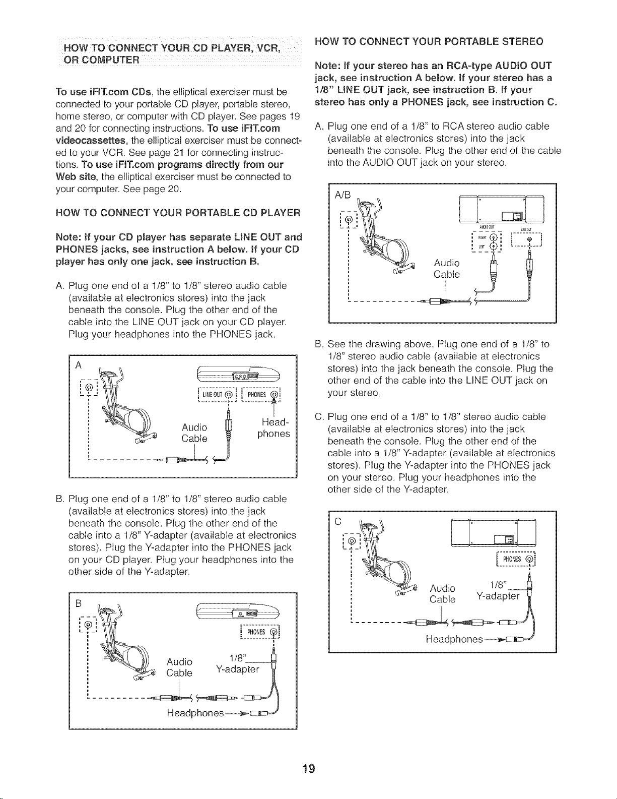
HOW TO CONNECT YOUR PORTABLE CD PLAYER
Note: if your CD pJayer has separate LINE OUT and
PHONES jacks, see instruction A beJow, if your CD
pJayer has only one jack, see instruction B.
A. Plug one end of a 1/8" to 1/8" stereo audio cable
(available at electronics stores) into the jack
beneath the console. Plug the other end of the
cable into the LINE OUT jack on your CD player.
Plug your headphones into the PHONES jack.
UNEO,T® i ]
Audio _ Head-
Cable phones
B. Plug one end of a 1/8" to 1/8" stereo audio cable
(available at electronics stores) into the jack
beneath the console. Plug the other end of the
cable into a 1/8" Y-adapter (available at electronics
stores). Plug the Y-adapter into the PHONES jack
on your CD player. Plug your headphones into the
other side of the Y-adapter.
Headphones__
HOW TO CONNECT YOUR PORTABLE STEREO
Note: ff your stereo has an RCA-type AUDIO OUT
jack, see instruction A beJow, ff your stereo has a
1/8" UNE OUT jack, see instruction B. ff your
stereo has only a PHONES jack, see instruction C.
A. Plug one end of a 1/8" to RCA stereo audio cable
(available at electronics stores) into the jack
beneath the console. Plug the other end of the cable
into the AUDIO OUT jack on your stereo.
AiB
: LER_ :
Audio
Cable
U_[_JT
B,
C,
See the drawing above. Plug one end of a 1/8" to
1/8" stereo audio cable (available at electronics
stores) into the jack beneath the console. Plug the
other end of the cable into the LINE OUT jack on
your stereo.
Plug one end of a 1/8" to 1/8" stereo audio cable
(available at electronics stores) into the jack
beneath the console. Plug the other end of the
came into a 1/8" Y-adapter (available at electronics
stores). Plug the Y-adapter into the PHONES jack
on your stereo. Plug your headphones into the
other side of the Y-adapter.
Cable Y-adapter _
Headphones _--@
19
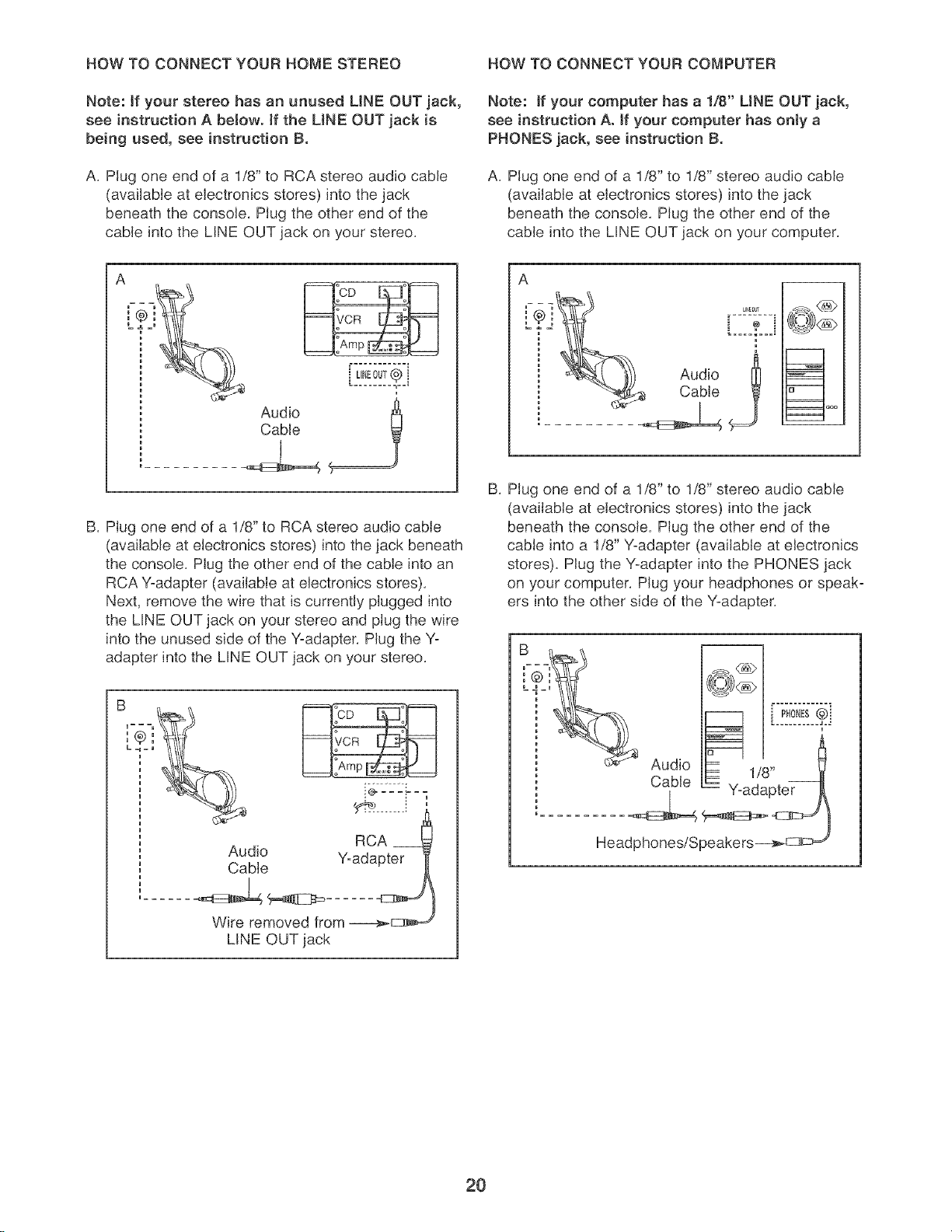
HOW TO CONNECT YOUR HOME STEREO HOW TO CONNECT YOUR COMPUTER
Note: if your stereo has an unused LiNE OUT jack,
see instruction A below, if the LiNE OUT jack is
being used, see instruction B.
A. Plug one end of a 1/8" to RCA stereo audio cable
(available at electronics stores) into the jack
beneath the console. Plug the other end of the
cable into the LINE OUT jack on your stereo.
Note: if your computer has a 1/8" LiNE OUT jack,
see instruction Ao if your computer has only a
PHONES jack, see instruction B.
A. Plug one end of a 1/8" to 1/8" stereo audio cable
(available at electronics stores) into the jack
beneath the console. Plug the other end of the
cable into the LINE OUT jack on your computer.
Audio
Cable
B. Plug one end of a 1/8" to RCA stereo audio cable
(available at electronics stores) into the jack beneath
the console. Plug the other end of the cable into an
RCA Y-adapter (available at electronics stores).
Next, remove the wire that is currently plugged into
the LINE OUT jack on your stereo and plug the wire
into the unused side of the Y-adapter. Plug the Y-
adapter into the LINE OUT jack on your stereo.
A
B. Plug one end of a 1/8" to 1/8" stereo audio cable
(available at electronics stores) into the jack
beneath the console. Plug the other end of the
cable into a 1/8" Y-adapter (available at electronics
stores). Plug the Y-adapter into the PHONES jack
on your computer. Plug your headphones or speak-
ers into the other side of the Y-adapter.
m
RCA
Audio Y-adapter
Cable
Wire removed from ----_=_
LINE OUT jack
2O
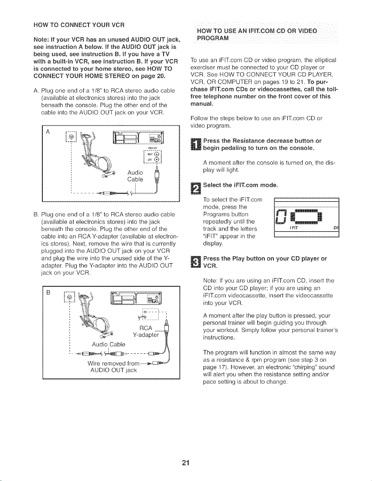
HOW TO CONNECT YOUR VCR
Note: if your VCR has an unused AUDIO OUT jack,
see instruction A below, if the AUDIO OUT jack is
being used, see instruction B. if you have a TV
with a built=in VCR, see instruction B. tf your VCR
is connected to your home stereo, see HOW TO
CONNECT YOUR HOME STEREO on page 20.
A, Plug one end of a 1/8" to RCA stereo audio cable
(available at electronics stores) into the jack
beneath the console, Plug the other end of the
cable into the AUDIO OUT jack on your VCR,
B, Plug one end of a 1/8" to RCA stereo audio cable
(available at electronics stores) into the jack
beneath the console, Plug the other end of the
cable into an RCA '-(-adapter (available at electron-
ics stores), Next, remove the wire that is currently
plugged into the AUDIO OUT jack on your VCR
and plug the wire into the unused side of the Yo
adapter, Plug the Yoadapter into the AUDIO OUT
jack on your VCR,
Z]
Audio Cable
/
Wire removed from_E::_m_,_
AUDIO OUT jack
HOW TO USE AN iFIT.COM CD OR VIDEO
PROGRAM
To use an iFiT,com CD or video program, the elliptical
exerciser must be connected to your CD player or
VCR, See HOW TO CONNECT YOUR CD PLAYER,
VCR, OR COMPUTER on pages 19 to 21, To pur-
chase iF[Tocom ODe or videocaasettes, ca[[ the toil-
free teJephone number on the front cover of this
manual
Follow the steps below to use an iF[T,com CD or
video program,
Press the Resistance decrease button or
begin pedaling to turn on the console.
A moment after the console is turned on, the dis°
play will light,
Select the iF[T.com mode.
To select the iFiT,com [.
mode, press the
Programs button
repeatedly until the
track and the letters
"iFIT" appear in the
display,
i FKT
Press the Play button on your CD player or
VCR.
Note: If you are using an iFIT,com CD, insert the
CD into your CD player; if you are using an
iFIT,com videocassette, insert the videocassette
into your VCR,
A moment after the play button is pressed, your
personal trainer will begin guiding you through
your workout, Simply follow your personal trainer's
instructions,
The program will function in almost the same way
as a resistance & rpm program (see step 3 on
page 17), However, an electronic "chirping" sound
wiil alert you when the resistance setting and/or
pace setting is about to change,
21
Note: if the resistance of the pedaJa and/or the
pace setting does not change when a "chirp"
is heard:
° Make sure that the letters "iFIT" appear in
the display.
°Adjust the volume of your CD ptayer or VCR.
if the volume is too high or too low, the con-
soJe may not detect the program signaJs.
° Make sure that the audio cabJe is properly
connected and that it is fully plugged in.
Monitor your progress with the disptayo
See step 4 on page 13.
Measure your heart rate as desired.
See step 5 on page 14.
Turn on the fan if desired.
See step 6 on page 14.
When you are finished exercising, the console
wHI automatically turn off.
See step 7 on page 14.
HOWTO USE AN IFiT.COM PROGRAM
DIRECTLY PROM OUR WEB SITE
Our Web site at wwwJFIT.com allows you to play
iFIT.com programs directly from the intemet. To use
programs from our Web site, the elliptical exerciser
must be connected to your home computer. See HOW
TO CONNECT YOUR COMPUTER on page 20. In
addition, you must have an internet connection and an
intemet service provider. A list of specific system
requirements is found on our Web site.
Follow the steps below to use a program from our
Web site.
Press the Resistance decrease button or
begin pedaling to turn on the console.
A moment after the console is turned on, the dis-
play will light.
Select the iFIT.com mode.
See step 2 on page 21.
Go to your computer and start an internet
connection.
Start your Web browser, if necessary, and go
to our Web site at www.iFIT.com.
Follow the desired links on our Web site to
select a program.
Read and follow the on=line instructions for using
a program.
Follow the onqine instructions to start the
program.
When you start the program, an on=screen count-
down will begin.
Return to the ellipticaJ exerciser and begin
pedaJing.
When the on-screen countdown ends, the pro-
gram will begin. The program will function in
almost the same way as a resistance & rpm pro-
gram (see step 3 on page 17). However, an elec-
tronic "chirping" sound will alert you when the resis=
tance setting and/or pace setting is about to
change.
Monitor your progress with the diaptay.
See step 4 on page 13.
Measure your heart rate if desired.
See step 5 on page 14.
Turn on the fan if desired.
See step 6 on page 14.
When you are finished exercising, the con-
sole will automatically turn off.
See step 7 on page 14.
22
MAINTENANCE AND TROUBLESHOOTING
Inspect and tighten all parts of the elliptical exerciser
regularly. Replace any worn parts immediately.
To clean the elliptical exerciser, use a damp cloth and
a small amount of mild soap. important: To avoid
damage to the console, keep liquids away from
the consote and keep the console out of direct
sunlight.
BATTERY REPLACEMENT
If the console displays become dim, the batteries
should be replaced; most console problems are the
result of low batteries. See assembly step 7 on page
7 for replacement instructions.
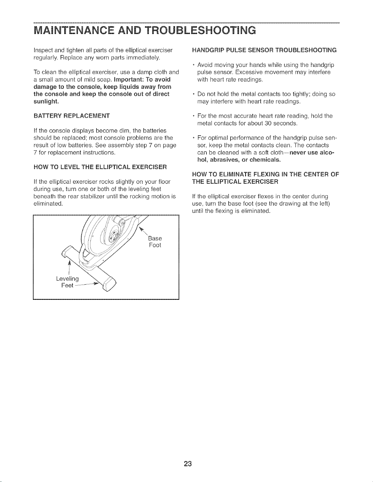
HOW TO LEVEL THE ELLIPTICAL EXERCISER
If the elliptical exerciser rocks slightly on your floor
during use, turn one or both of the leveling feet
beneath the rear stabilizer until the rocking motion is
eliminated.
HANBGRIP PULSE SENSOR TROUBLESHOOTING
. Avoid moving your hands while using the handgnp
pulse sensor. Excessive movement may interfere
with heart rate readings.
• Do not hold the metal contacts too tightly; doing so
may interfere with heart rate readings.
• For the most accurate heart rate reading, hold the
metal contacts for about 30 seconds.
For optimal performance of the handgrip pulse sen-
sor, keep the metal contacts clean. The contacts
can be cleaned with a soft cloth--never use alco-
hol, abrasives, or chemicals.
HOW TO EMMINATE FLEXING IN THE CENTER OF
THE ELMPTJCAL EXERCISER
If the elliptical exerciser flexes in the center during
use, turn the base foot (see the drawing at the left)
until the flexing is eliminated.
Base
Foot
Leveling
Feet
23
CONDiTiONiNG GUiDELiNES
AVCARNING:
Before beginning this or any exercise pro-
gram, consult your physician. This is espe=
cially important for persons over the age of 35
or persons with pre-existing health problems.
The pulse sensor is not a medical device.
Various factors may affect the accuracy of
heart rate readings. The pulse sensor is
intended only as an exercise aid in determin-
ing heart rate trends in general.
The following guidelines will help you to plan your
exercise program, Remember that proper nutrition
and adequate rest are essential for successful results,
EXERCISE iNTENSITY
Whether your goal is to burn fat or to strengthen your
cardiovascular system, the key to achieving the
desired results is to exercise with the proper intensity.
The proper intensity level can be found by using your
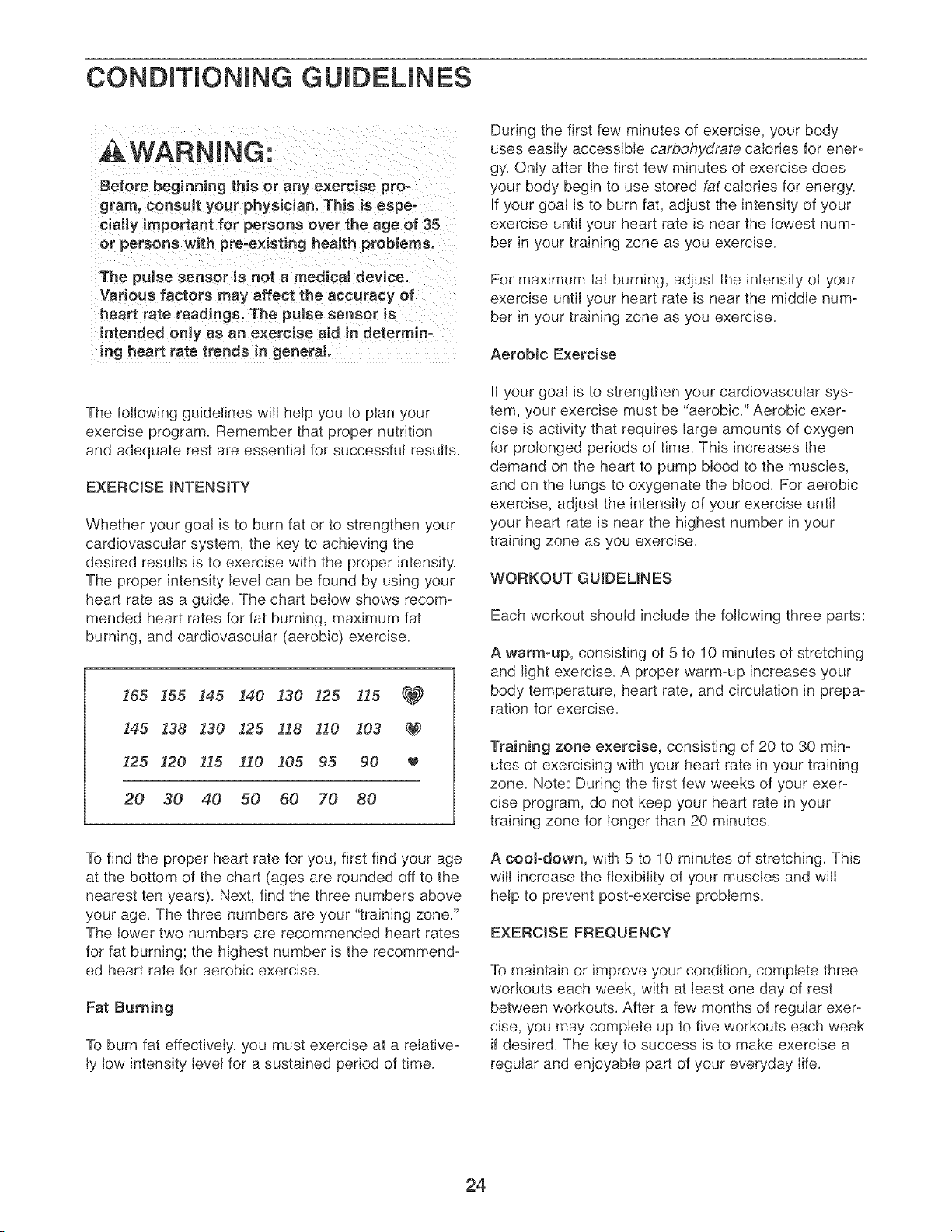
heart rate as a guide. The chart below shows recom-
mended heart rates for fat burning, maximum fat
burning, and cardiovascular (aerobic) exercise.
165 !55 !45 140 130 i25 115 _
145 138 130 125 118 !10 103 _
125 120 115 I10 105 95 90
20 30 40 50 60 70 80
To find the proper heart rate for you, first find your age
at the bottom of the chart (ages are rounded off to the
nearest ten years). Next, find the three numbers above
your age. The three numbers are your "training zone."
The lower two numbers are recommended heart rates
for fat burning; the highest number is the recommend-
ed heart rate for aerobic exercise.
Fat Burning
To burn fat effectively, you must exercise at a relative-
ly low intensity level for a sustained period of time.
During the first few minutes of exercise, your body
uses easily accessible carbohydrate calodes for ener-
gy. Only after the first few minutes of exercise does
your body begin to use stored fat calories for energy.
If your goal is to burn fat, adjust the intensity of your
exercise until your heart rate is near the lowest num-
ber in your training zone as you exercise.
For maximum fat burning, adjust the intensity of your
exercise until your heart rate is near the middle num-
ber in your training zone as you exercise.
Aerobic Exercise
If your goal is to strengthen your cardiovascular sys-
tem, your exercise must be "aerobic." Aerobic exer-
cise is activity that requires large amounts of oxygen
for prolonged periods of time. This increases the
demand on the heart to pump blood to the muscles,
and on the lungs to oxygenate the blood. For aerobic
exercise, adjust the intensity of your exercise until
your heart rate is near the highest number in your
training zone as you exercise.
WORKOUT GU!BEMNES
Each workout should include the following three parts:
A warm-up, consisting of 5 to 10 minutes of stretching
and light exercise. A proper warm-up increases your
body temperature, heart rate, and circulation in prepa-
ration for exercise.
Training zone exercise, consisting of 20 to 30 min-
utes of exercising with your heart rate in your training
zone. Note: During the first few weeks of your exer-
cise program, do not keep your heart rate in your
training zone for longer than 20 minutes.
A cooJ-down, with 5 to 10 minutes of stretching. This
will increase the flexibility of your muscles and will
help to prevent post-exercise problems.
EXERCISE FREQUENCY
To maintain or improve your condition, complete three
workouts each week, with at least one day of rest
between workouts. After a few months of regular exer-
cise, you may complete up to five workouts each week
if desired. The key to success is to make exercise a
regular and enjoyable part of your everyday life.
24
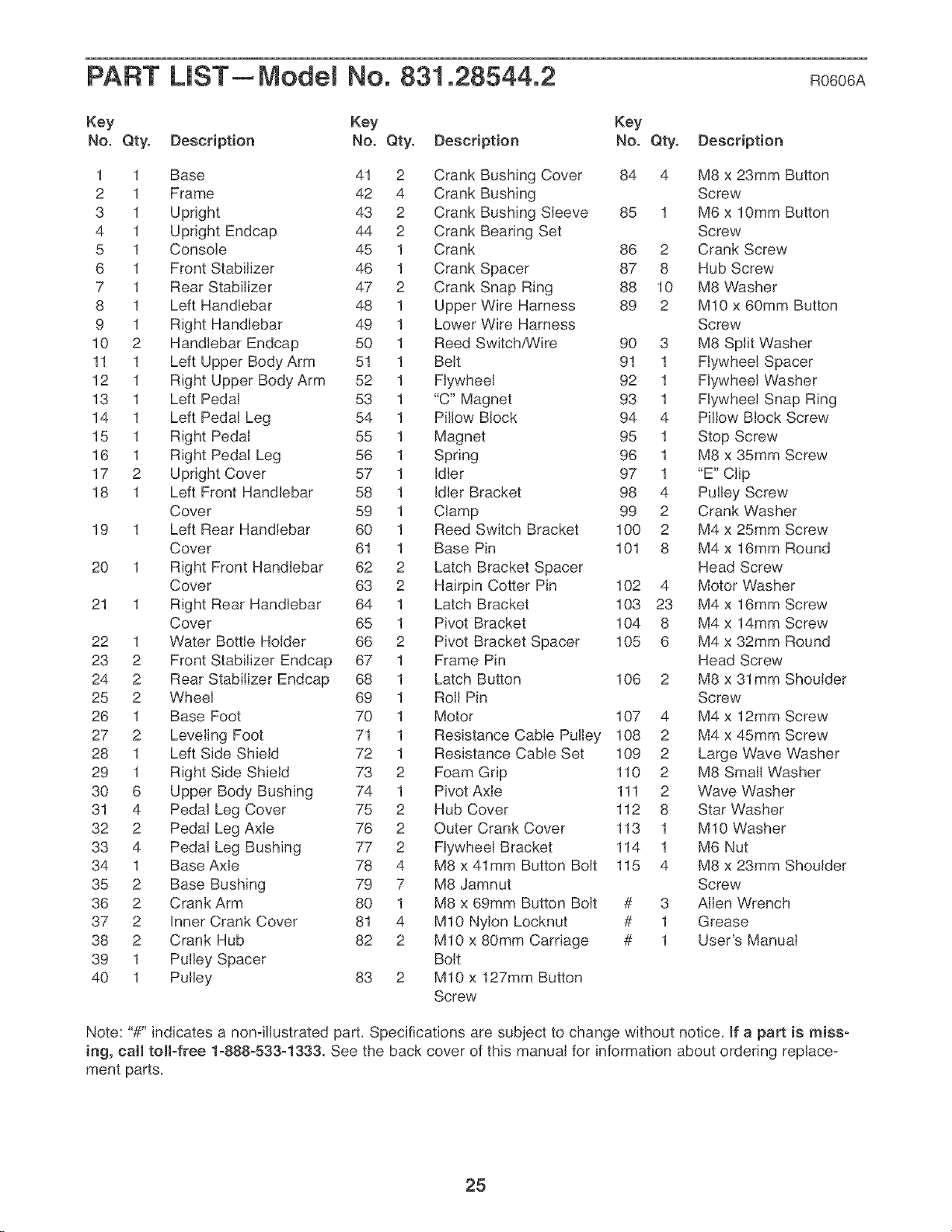
PART LIST--Model No. 831.28544.2 Ro6o6A
Key Key Key
No. Qty. Description No. Qty. Description No. Qty. Description
1 1 Base 41 2 Crank Bushing Cover 84 4 M8 x 23mm Button
2 1 Frame 42 4 Crank Bushing Screw
3 1 Upright 43 2 Crank Bushing Sleeve 85 1 M6 x 10mm Button
4 1 Upright Endcap 44 2 Crank Bearing Set Screw
5 1 Console 45 1 Crank 86 2 Crank Screw
6 1 Front Stabilizer 46 1 Crank Spacer 87 8 Hub Screw
7 1 Rear Stabilizer 47 2 Crank Snap Ring 88 10 M8 Washer
8 1 Left Handlebar 48 1 Upper Wire Harness 89 2 M10 x 60mm Button
9 1 Right Handlebar 49 1 Lower Wire Harness Screw
10 2 Handlebar Endcap 50 1 Reed Switch,_/ire 90 3 M8 Split Washer
11 1 Left Upper Body Arm 51 1 Belt 91 1 Flywheel Spacer
12 1 Right Upper Body Arm 52 1 Flywheel 92 1 Flywheel Washer
13 1 Left Pedal 53 1 "C" Magnet 93 1 Flywheel Snap Ring
14 1 Left Pedal Leg 54 1 Pillow Block 94 4 Pillow Block Screw
15 1 Right Pedal 55 1 Magnet 95 1 Stop Screw
16 1 Right Pedal Leg 56 1 Spring 96 1 M8 x 35mm Screw
17 2 Upright Cover 57 1 Idler 97 1 "E" Clip
18 1 Left Front Handlebar 58 1 Idler Bracket 98 4 Pulley Screw
Cover 59 1 Clamp 99 2 Crank Washer
19 1 Left Rear Handlebar 60 1 Reed Switch Bracket 100 2 M4 x 25mm Screw
Cover 61 1 Base Pin 101 8 M4 x 16mm Round
20 1 Right Front Handlebar 62 2 Latch Bracket Spacer Head Screw
Cover 63 2 Hairpin Cotter Pin 102 4 Motor Washer
21 1 Right Rear Handlebar 64 1 Latch Bracket 103 23 M4 x 16mm Screw
Cover 65 1 Pivot Bracket 104 8 M4 x 14mm Screw
22 1 Water Bottle Holder 66 2 Pivot Bracket Spacer 105 6 M4 x 32mm Round
23 2 Front Stabilizer Endcap 67 1 Frame Pin Head Screw
24 2 Rear Stabilizer Endcap 68 1 Latch Button 106 2 M8 x 31mm Shoulder
25 2 Wheel 69 1 Roll Pin Screw
26 1 Base Foot 70 1 Motor 107 4 M4 x 12mm Screw
27 2 Leveling Foot 71 1 Resistance Cable Pulley 108 2 M4 x 45mm Screw
28 1 Left Side Shield 72 1 Resistance Cable Set 109 2 Large Wave Washer
29 1 Right Side Shield 73 2 Foam Grip 110 2 M8 Small Washer
30 6 Upper Body Bushing 74 1 Pivot Axle 111 2 Wave Washer
31 4 Pedal Leg Cover 75 2 Hub Cover 112 8 Star Washer
32 2 Pedal Leg Axle 76 2 Outer Crank Cover 113 1 M10 Washer
33 4 Pedal Leg Bushing 77 2 Flywheel Bracket 114 1 M6 Nut
34 1 Base Axle 78 4 M8 x 41mm Button Bolt 115 4 M8 x 23mm Shoulder
35 2 Base Bushing 79 7 M8 Jamnut Screw
36 2 Crank Arm 80 1 M8 x 69mm Button Bolt # 3 Allen Wrench
37 2 Inner Crank Cover 81 4 M10 Nylon Locknut # 1 Grease
38 2 Crank Hub 82 2 M10 x 80mm Carriage # 1 User's Manual
39 1 Pulley Spacer Bolt
40 1 Pulley 83 2 M10 x 127mm Button
Screw
Note: "#" indicates a nonqllustrated part, Specifications are subject to change without notice, If a part is miss-
ing, call toll-free 1-888-533-1333. See the back cover of this manual for information about ordering replace°
ment parts,
25
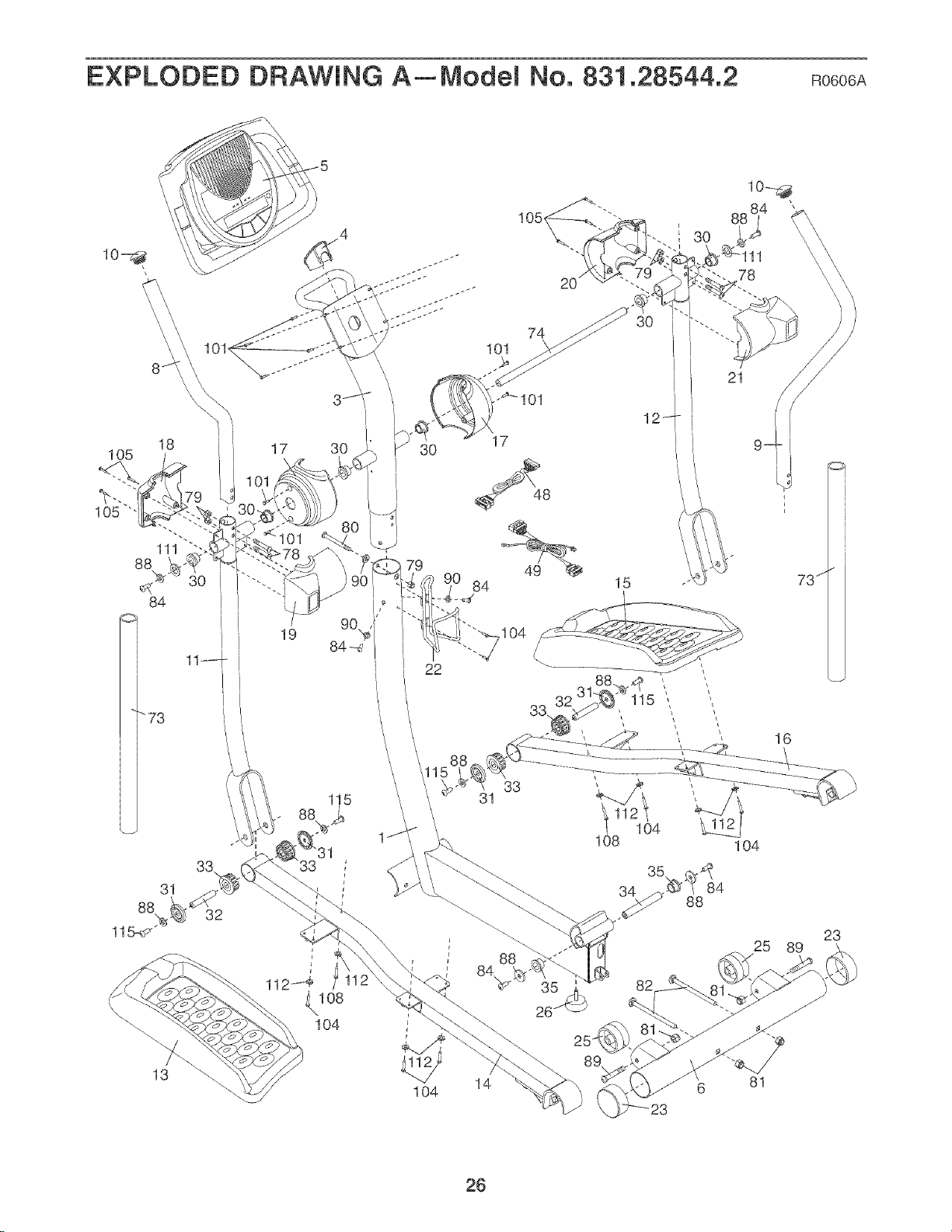
EXPLODED DRAWING A_Model No. 831.28544.2 Ro6o6A
19 04
22
I 3O
78
33
31
115
21
31
33,
32
31
1O4
\
\
104
r
88
26
82
25 89
13
1O4
14
81
23
26
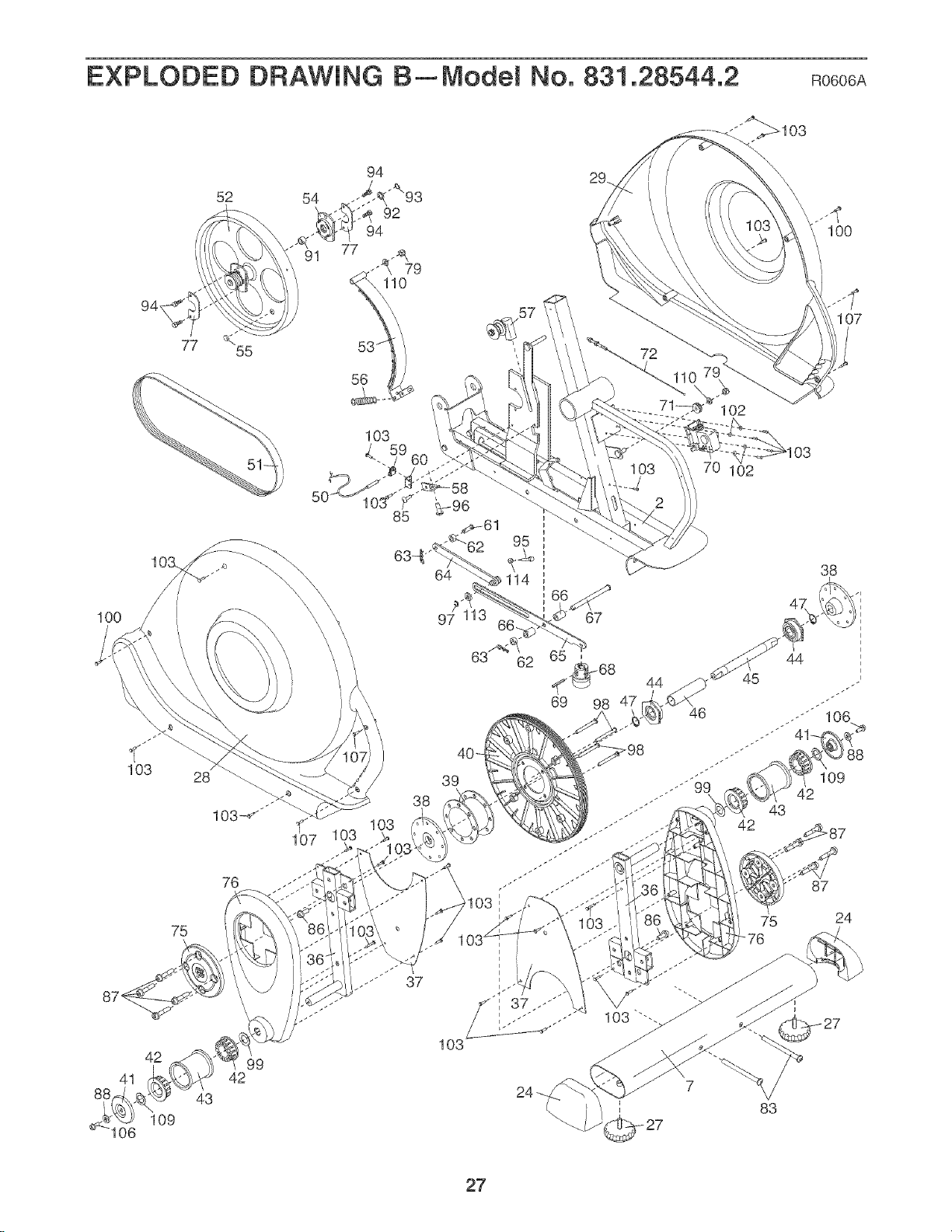
EXPLODED DRAWING B_Model No. 831.28544.2 Ro6o6A
52 54
IO0
94,
IO0
103
41
106
77
55
76
75
42 99
42
43
109
39
38
103
44
46
102
102
75
42
43
83
107
38
_8
109
87
24
27

Get it fixed, at your home or ours!
Your Home
For repair--in your home--of all major brand appliances, lawn and garden equipment.
or heating and cooling systems, no matter who made it, no matter who sold it!
For the re placement parts, accessories, and user's manuals that you need to do-it-yourself.
For Sears professional installation of home appliances
and items ike garage door openers and water heaters.
1-800-4-MY-HOME _ (1-800-469-4663)
Call anytime, day or night _U.S.A. and CanadaJ
www, sears.com www.sears.ca
Our Home
For repair of carry-in items like vacuums, lawn equipment
and electronics, cal or go on-line for the location of your nearest
Sears Parts & Repair Center.
1-800-488-1222 Call anytime, day or night fU.S.A, only)
www.sears.com
To purchase a protection agreement (U.S.A.)
or maintenance agreement (Canada) on a product serviced by Sears:
1-800-827-6655 (U.S.A./ 1-800-361-6665 (Canada/
Para pedir servicio de reparacidn a domicilio, y para ordenar piezas:
1-888-SU-HOGAR _ _1-888-784-6427/
f_
TM SM
® Registered Trademark / Trademark / Service Mark of Sears Brands, LLC
_ Marca Registrada / TMMarca de F_,brica / SMMarca de Servicio de Sears Brands, LLC
90 DAY FULL WARRANTY
f
If this Sears Elliptical Exerciser fails due to a defect in material or workmanship within 90 days of the
date of purchase, call 1-800-4-MYoHOME <'_(1o800o469o4663) to arrange for free repair (or replacement
if repair proves impossible
This warranty does not apply when the Elliptical Exerciser is used commercially or for rental purposes,
This warranty gives you specific legal rights, and you may also have other rights which vary from state
to state.
Sears, Roebuck and Co., Hoffman Estates, IL 60179
J
J
Part No, 241454 R0606A Printed in China ¢_2006 ICON IP, Inc,