SWAURS
OWNER'S
MANUAL
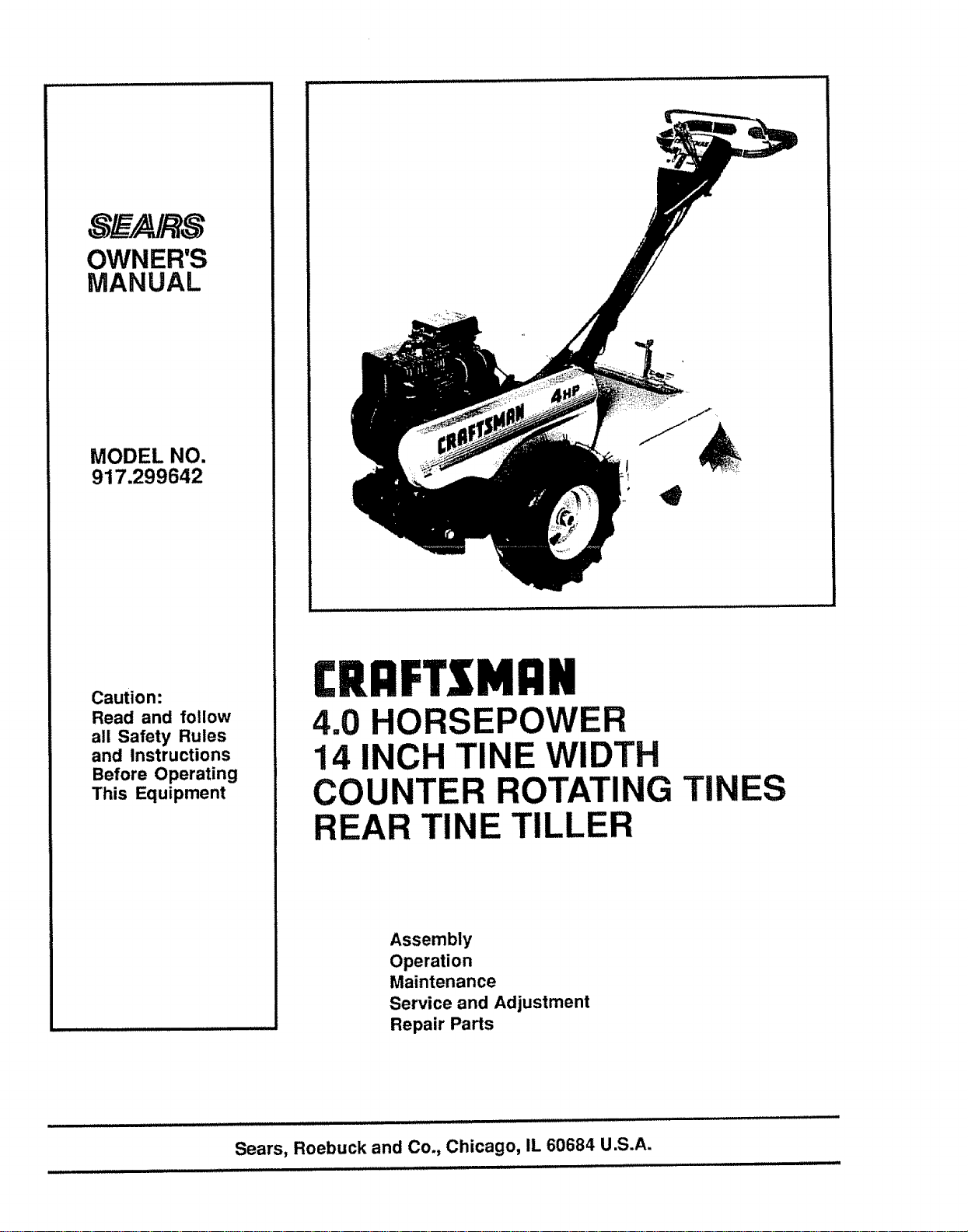
MODEL NO,
917.299642
Caution:
Read and follow
all Safety Rules
and Instructions
Before Operating
This Equipment
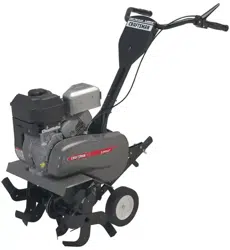
£RI:IFTSMI:IN
4.0 HORSEPOWER
14 INCH TINE WIDTH
COUNTER ROTATING TINES
REAR TINE TILLER
Assembly
Operation
Maintenance
Service and Adjustment
Repair Parts
Sears, Roebuck and Co., Chicago, IL 60684 U.S.A.
SAFETY RULES
Safe Operation Practices for Walk-Behind Powered Rotary Tillers
&
TRAINING
- Read the operating and service instructionmanual
carefully. Be thoroughlyfamiliar with the controls and
the proper use of the equipmentv Know howto stopthe
unit and disengage the controls quickly_
• Never allow children to operate the equipment° Never
allow adults to operate the equipment without proper
instruction
. Keep the area of operation clear of all persons, particu-
larly small children, and pets_
PREPARATION
° Thoroughly inspectthe area where the equipment isto
be used and removeall foreign objects°
. Disengage all clutches and shift into neutral before
starting the engine (motor)..
= Do not operate the equipment without wearing ade-
quate outer garments.. Wear footwear that will improve
footing on slippery" surfaces.
. Handle fuel with care; it is highly flammable..
• Use an approved fuel container.,
• Never add fuel to a running engine or hot engine.
• Fillfuel tank outdoors with extreme care. Never fill
fuel tank indoors_
• Replace gasoline cap securely and clean up spilled
fuel before restarting
• Use extension cords and receptaclesasspecified bythe
manufacturer for all units with electric drive motors or
electric starting motors.
• Never attempt to make any adjustments while the engine
(motor) is running (except where specifically recom-
mended by manufacturer),
OPERATION
. Do not put hands or feet near or under rotating parts.,
° Exercise extreme caution when operating on or crossing
gravel drives, walks, or roads_ Stay alert for hidden
hazards or traffic, Do not carry passengers,
• After' striking a foreign object, stop the engine (motor),
remove the wire from the spark plug, thoroughly inspect
the tiller for any damage, and repair the damage before
restarting and operating the tillers.
• Exercise caution to avoid slipping or falling.
. If the unit should start to vibrate abnormally, stop the
engine (motor) and check immediately forthe cause°Vi-
bration is generally a warning of trouble.,
. Stop the engine (motor) when leaving the operating
position, before unclogging the tines, and when making
any repair, adjustments, and inspections,
° Take all possible precaufionswhen leaving the machine
unattended., Disengage the power take-off, lower the
attachment, shift into neutral, stop the engine, and
remove the key.
• Before cleaning, repairing, or' inspecting, shut off the
engine and make certain all moving parts have stopped_
Disconnect the spark plug wire, and keep the wire away
from the plug to prevent accidental starting Disconnect
the cord on electric motors.
° Do not run the engine indoors;exhaust fumesare dan-
gerous.
• Never operate the tillerwithout properguards, plates, or
other safety protective devices in place.
• Keep children and pets away.
• Donotoverload the machine capacity by attempting totill
too deep at too fast a rate.
• Never allow bystanders near the unit.,
• Use only attachments and accessories approved by the
manufacturer ofthetirler(such aswheelweights, counter_
weights, cabs, and the like).
• Never operate the tillerwithout good visibility or light,
• Be careful when tilling in hard ground. The tines may
catch in the ground and propel the tiller forward. If this
occurs, let go of the handlebars and do not restrainthe
machine.
MAINTENANCE AND STORAGE
• Keep machine, attachments, and accessories in safe
workingcondition..
. Check shear bolts, engine mounting bolts, and other
bolts at frequent intervalsfor propertightnessto besure
the equipmentisin safe workingcondition_
. Never storethe machine withfuel inthe fuel tankinside
abuildingwhere ignitionsourcesare present,suchas hot
water and space heaters, clothesdryers, and the like.
Allowthe enginetocoolbeforestoringinany enclosure.,
. Always refer to the Owner's Manual instructionsfor im-
portantdetails ifthe tiller isto be storedfor an extend-
ed period.
-IMPORTANT -
Warnings, Cautions, and Notes are a means of attracting attentionto importantor criticalinformationinthis manual.,
illll i ill i i illl illlllllllllllllll illlll
LOOK FOR THIS SYMBOL TO POINT
OUT IMPORTANT SAFETY PRE-
CAUTIONS. IT MEANS -- ATTENTION!
BECOME ALERT! YOUR SAFETY IS
INVOLVED.
CAUTION: USED TO ALERT YOU THAT THERE IS
A POSSIBILITY OF DAMAGING THIS
EQUIPMENT_
NOTE: Gives essential informationthat will aid you to
better understand, incorporate, or execute a particular
set of instructions.
2
CONGRATULATIONS on your purchase of a Sears
Craftsman Tiller° it has been des=gned,engineered and
manufacturedto give you the bestpossibledependability
and performance.
Should you experience any problemsyou cannoteasily
remedy, please contactyournearest Sears Service Cen-
teriDepartmentoWe have competent,well trainedtechni-
cians and the propertoolstoservice or repairthisunit
Please read and retain this manual. The instructionswill
enable you to assembleand maintainyour Tiller prop-
erty, Always observethe SAFETY RULES
MODEL
NUMBER 917.299642
SERIAL
NUMBER
DATE OF
PURCHASE
THE MODEL AND SERIAL NUMBERS WILL BE
FOUND ON THE MODEL PLATE ATTACHED TO
THE TOP OF THE TRANSMISSION,
YOU SHOULD RECORD BOTH SERIAL NUMBER
AND DATE OF PURCHASE AND KEEP IN A SAFE
PLACE FOR FUTURE REFERENCE,,
PRODUCT SPECIFICATIONS
HORSEPOWER: 4_0
DISPLACEMENT: 11,39 CUoIN,,
GASOLINE CAPACITY: 2 QUART
(UNLEADED)
OIL (20 OZ. CAPACITY): SAE 30W
(SAE 10W 30)
SPARK PLUG (GAP ,030 IN,): CHAMPION
RCJ8
MAINTENANCE AGREEMENT
A Sears Maintenance Agreement is available on this
product. Contact your nearest Sears store'for details,
CUSTOMER RESPONSIBILITIES
. Read and observe the safety rules.
• Follow a regular schedule in maintaining, caring for and using your Tiller_
. Fo_towthe instructionsunder Maintenance" and "Storage" sections of thisOwner's Manual,,
LIMITED ONE YEAR LIMITED WARRANTY ON CRAFTSMAN TILLER
For one year from date of purchase, when this Craftsman Tiller is maintained, lubricated, and tuned up ac-
cording to the instructions in the owner s manual, Sears wilt repair, free of charge, any detect in material and
workmanship,,
If this Craftsman Tiller is used for commercial or rental purposes, this Warranty applies for only 30 days from
the date of purchase.
This Warranty does not cover:
• expendable itemswhich become worn during normal use, such as tines, spark plug, air cleaners and bells,
• Repairs necessary because of operator abuse or negligence, including bent crankshafts and the failure to
maintain the equipment according to the instructions contained in the owner's manual
WARRANTY SERVICE IS AVAILABLE BY RETURNING THE CRAFTSMAN TILLER TO THE NEAREST
SEARS SERVICE CENTER/DEPARTMENT IN THE UNITED STATES. THIS WARRANTY APPLIES ONLY
WHILE THIS PRODUCT iS IN USE IN THE UNITED STATES
This Warranty gives you specific legal rights, and you may also have other rights which vary from state to
state.,
Sears, Roebuck and Co., D/731CR-W, Sears Tower, Chicago, IL 60684
-NOTE-
This unit is equipped with an internalcombustion engine and should not be used on or near any unimprovedforest-
covered, brush-covered or grass covered land unless the engine's exhaust system is equipped with a spark arrester
meetingapplicablelocal or state laws(if any). Ifa spark arrester isused, itshouldbe maintained in effectiveworkingorder
by the operator.
in the state of Californiathe above is required by law (Section 4442 of the California Public Resources Code) Other
states may have similar laws. Federal laws apply on federal lands, See your Sears Authorized Service Center for spark
arrester. Refer topage 33 of Repair Partssection ofthis manualfor part number.
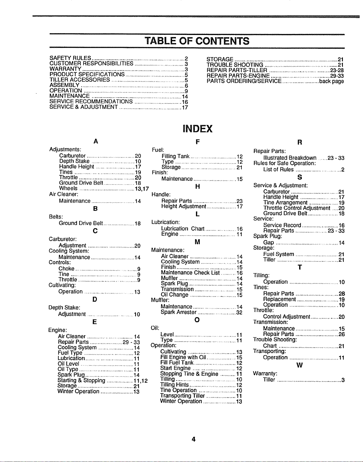
TABLE OF CONTENTS
, iii1,,Jl,Jll,,,Jlll,,Ji J, i, ,,ulJl, i,ii,llll,ll,,ii,u,lll iin i ii i i ii i i i
SAFETY RULES ............................................................................ 2
CUSTOMER RESPONSIBILITIES ...............................................3
WARRANTY ...............................................................................3
PRODUCT SPECI FICATtONS ..................................................5
TILLER ACCESSORIES ........................................................................5
ASSEMBLY ...................................................................................................................6
OPERATION ............................................................................................9
MAINTENANCE .............................................................................14
SERVICE RECOMMENDATIONS ...........................................16
SERVICE & ADJUSTMENT ..............................................................17
STORAGE .................................................................... 21
TROUBLE SHOOTING .......................................................................21
REPAIR PARTS-TILLER ...........................................................23-28
REPAIR PARTS-ENGINE .......................................................29-33
PARTS ORDERING/SERViCE ................................back page
A
Adjustments:
Carburetor ......................................................20
Depth Stake ...............................................10
Handle Height .....................................17
Tines .........................................................19
Throttle ...............................................20
Ground Drive Belt ................................18
Wheels ....................................................13,17
Air Cleaner:
Maintenance ......................................14
B
Belts:
Ground Drive Belt.................................18
C
Carburetor':
Adjustment ......................................20
Cooling System:
Maintenance.........................................14
Controls:
Choke ..................................................9
Tine .................................................................9
Throttle ..............................................9
Cultivating:
Operation ....................................13
D
Depth Stake:
Adjustme nt ..........................................10
E
Engine:
Air'Cleaner .....................................14
Repair Parts ..................................29 - 33
Cooling System .....................................14
Fuel Type ...........................................12
Lubrication.........................................11
Oil Level .........................................................11
Oil Type ..................................................11
Spark Plug ...............................................14
Starting & Stopping ..........................11,t2
Storage .................................................21
Winter Operation ................................13
INDEX
F
Fuel:
Filling Tank ..................................................12
Type ................................................12
Storage ...........................................................21
Finish:
Maintenance ...........................................15
H
Handle:
Repair Parts .....................................23
Height Adjustment ........................17
L
Lubrication:
Lubrication Chart ..............................16
Engine .................................................11
M
Maintenance:
Air Cleaner. ...............................14
Cooling System ......................................14
Finish ................................................15
Maintenance Check List ...............i6
Muffler ...................................................14
Spark Plug..........................................14
Transmission .................................15
Oil Change ..........................................15
Muffler:
Maintenance.....................................14
Spark Arrester ...............................32
O
Oil:
Level .........................................................11
Type .....................................................11
Operation:
Cultivating.....................................13
Fill Engine with Oil ......................15
Fill Fuel Tank ..............................12
Start Engine ....................................12
Stopping Tine & Engine ..............11
Tilling .....................................................10
Tilling Hints ..................................t2
Tine Operation ...................................10
Transporting Tiller ......................11
Winter Operation ..............................13
R
Repair Parts:
Illustrated Breakdown ........23 - 33
Rules for Safe Operation:
List of Rules .....................................2
S
Service & Adjustment:
Carburetor .......................................21
Han_lle Height ................................17
Tine Arrangement ..........................19
Throttle Control Adjustment ....20
Ground Drive Belt ............................I8
Service:
Service Record ...................................16
Repair Parts...........................23 - 33
Spark Plug:
Gap ........................................................t4
Storage:
Fuel System ...................................21
Tiller ........................................................21
T
Tilling:
Operation ....................................................10
Tines:
Repair Parts .................................28
Replacement ..................................19
Operation ...............................................10
Throttle:
Control Adjustment .....................20
Transmission:
Maintenance ..................................15
Repair Parts .................................26
Trouble Shooting:
Chart ..................................................21
Transporting:
Operation .........................................11
W
Warranty:
Tiller .......................................................3
4
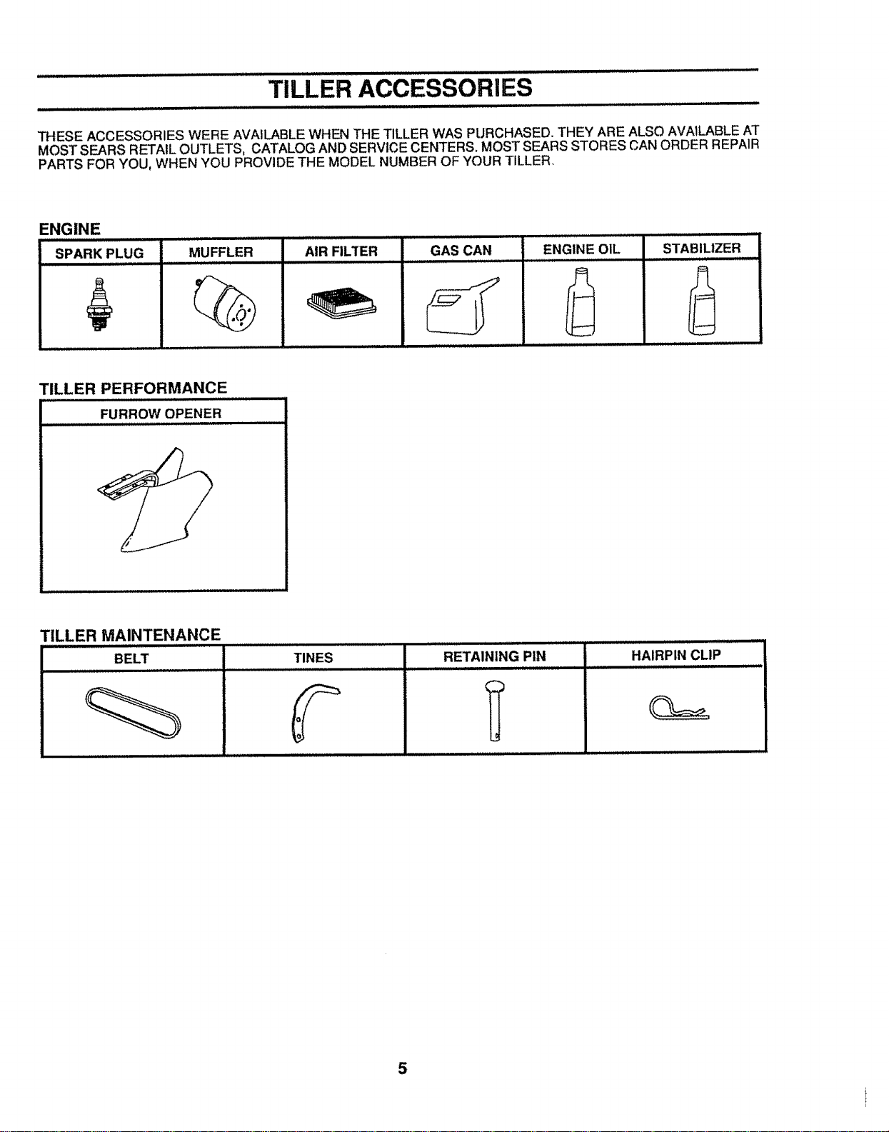
TILLER ACCESSORIES
THESE ACCESSORIES WERE AVAILABLE WHEN THE TILLER WAS PURCHASED. THEY ARE ALSO AVAILABLE AT
MOST SEARS RETAIL OUTLETS, CATALOG AND SERVICE CENTERS. MOST SEARS STORES CAN ORDER REPAIR
PARTS FOR YOU, WHEN YOU PROVIDE THE MODEL NUMBER OF YOUR TILLER,
ENGINE
SPARK PLUG
MUFFLER
%
AIR FILTER GAS CAN
ENGINE OIL
STABILIZER
ill, lll,ii
,2
TILLER PERFORMANCE
FURROW OPENER
TILLER MAINTENANCE
...................... , i............ ,i ....
BELT TINES RETAINING PIN HAIRPIN CLIP
................. iii iljlllll I I II IIIIII1[
5
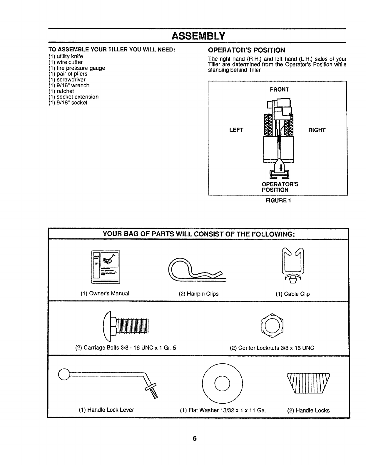
ASSEMBLY
TO ASSEMBLE YOUR TILLER YOU WILL NEED:
(1) utility knife
(1) wire cutter
(1) tire pressure gauge
(1) pair of pliers
(1) screwdriver
(1) 9/16" wrench
(1) ratchet
(1) socket extension
(1) 9/16" socket
OPERATOR'S POSITION
The right hand (RH.) and left hand (LH,) sides of your
Tiller are determined from the Operator's Position while
standing beilind Tiller
FRONT
LEFT RIGHT
OPERATOR'S
POSITION
FIGURE 1
YOUR BAG OF PARTS WILL CONSIST OF THE FOLLOWING:
(1) Owner's Manual
(2) Hairpin Clips (1) Cable Clip
IIIIIIIIIIIlUlIIIIIIIIIIIIIlUlUlIII I I III1'11'11'111111 I I I .....
(2) Carriage Bolts 3/8 - 16 UNC x 1 Gr..5
O
(1) Handle Lock Lever
iiiiiiii ilUl,ll,ll_UUll,i-iiiuii ii iiiii
O
(2) Center Locknuts 3/8 x 16 UNC
(1) Fiat Washer 13/32 x 1 x 11 Ga.
iiiiiiiiiiiiii ii I iiiii I i i
(2) Handle Locks
6
ASSEMBLY
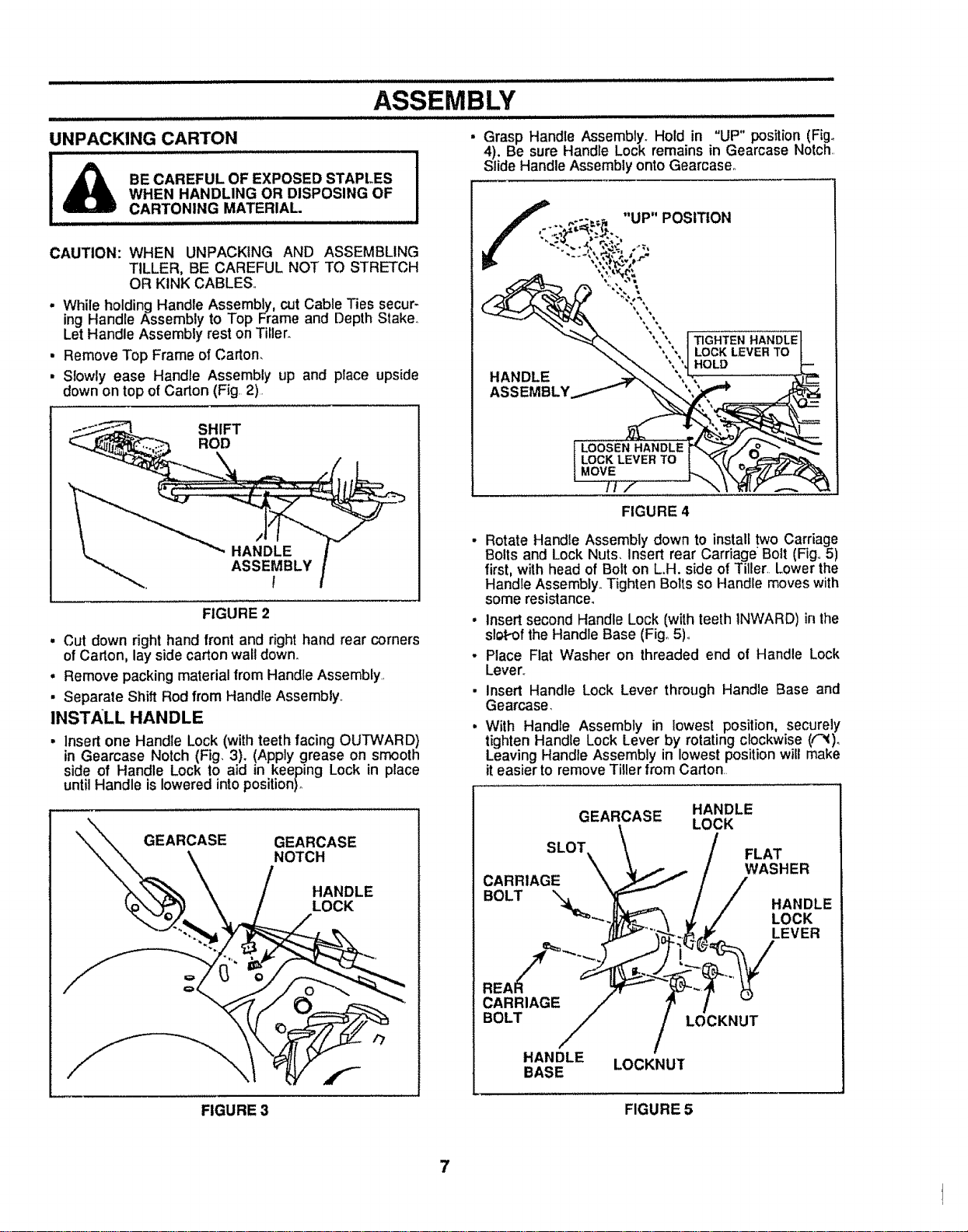
UNPACKING CARTON
BE CAREFUL OF EXPOSED STAPLES
WHEN HANDLING OR DISPOSING OF
CARTONING MATERIAL.
.... H,H,
CAUTION: WHEN UNPACKING AND ASSEMBLING
TILLER, BE CAREFUL NOT TO STRETCH
OR KINK CABLES,,
. While holding Handle Assembly, cut Cable Ties secur-
ing Handle Assembly to Top Frame and Depth Slake°
Let Handle Assembly rest on Tiller.
• Remove Top Frame of Carton.
• Slowly ease Handle Assembly up and place upside
down on top ofCarton (Fig. 2).
FIGURE 2
• Cut down right hand front and right hand rear corners
of Carton, lay side carton wall down.,
• Remove packing material from Handle Assembly,,
• Separate Shift Rod from Handle Assembly,
INSTALL HANDLE
• Insertone Handle Lock (with teeth facing OUTWARD)
in Gearcase Notch (Fig. 3). (Apply grease on smooth
side of Handle Lock to aid in keeping Lock in place
until Handle is lowered into position)°
GEARCASE GEARCASE
NOTCH
HANDLE
LOCK
Grasp Handle Assembly. Hold in "UP" position (Fig.
4), Be sure Handle Lock remains in Gearcase Notch,,
Slide Handle Assembly onto Gearcaseo
f ,...-..= "UP" POSITION
"": "" ', ', _GF'_'_EN HANDLE
"_._ "',", I LOCK LEVER TO
_?'_ " "t HOLD
HANDLE ==,_'_. ', -, ....
z
FIGURE 4
• Rotate Handle Assembly down to install two Carriage
Bolts and Lock Nuts, Insert rear Carriage Bolt (Fig,,5)
first, with head of Bolt on L.H. side of Tiller, Lower the
Handle Assembly,,Tighten Bolts so Handle moves with
some resistance.
• Insert second Handle Lock (with teeth INWARD) in the
slot-of the Handle Base (Fig,,5)°
- Place Flat Washer on threaded end of Handle Lock
Lever.,
• Insert Handle Lock Lever through Handle Base and
Gearcase.
• With Handle Assembly in lowest position, securely
tighten Handle Lock Lever by rotating clockwise ((_)o
Leaving Handle Assembly in lowest position wilt make
it easier to remove Tiller from Carton,
GEARCASE HANDLE
LOCK
\
SLOT \ / FLAT
c,
BOLT / / .ANDLE
"_'_-.JJ_- _ _,./ LOCK
CARRIAGE / ? /
BOLT LOCKNUT
HANDLE LOCKNUT
BASE
FIGURE 3
FIGURE 5
7
ASSEMBLY
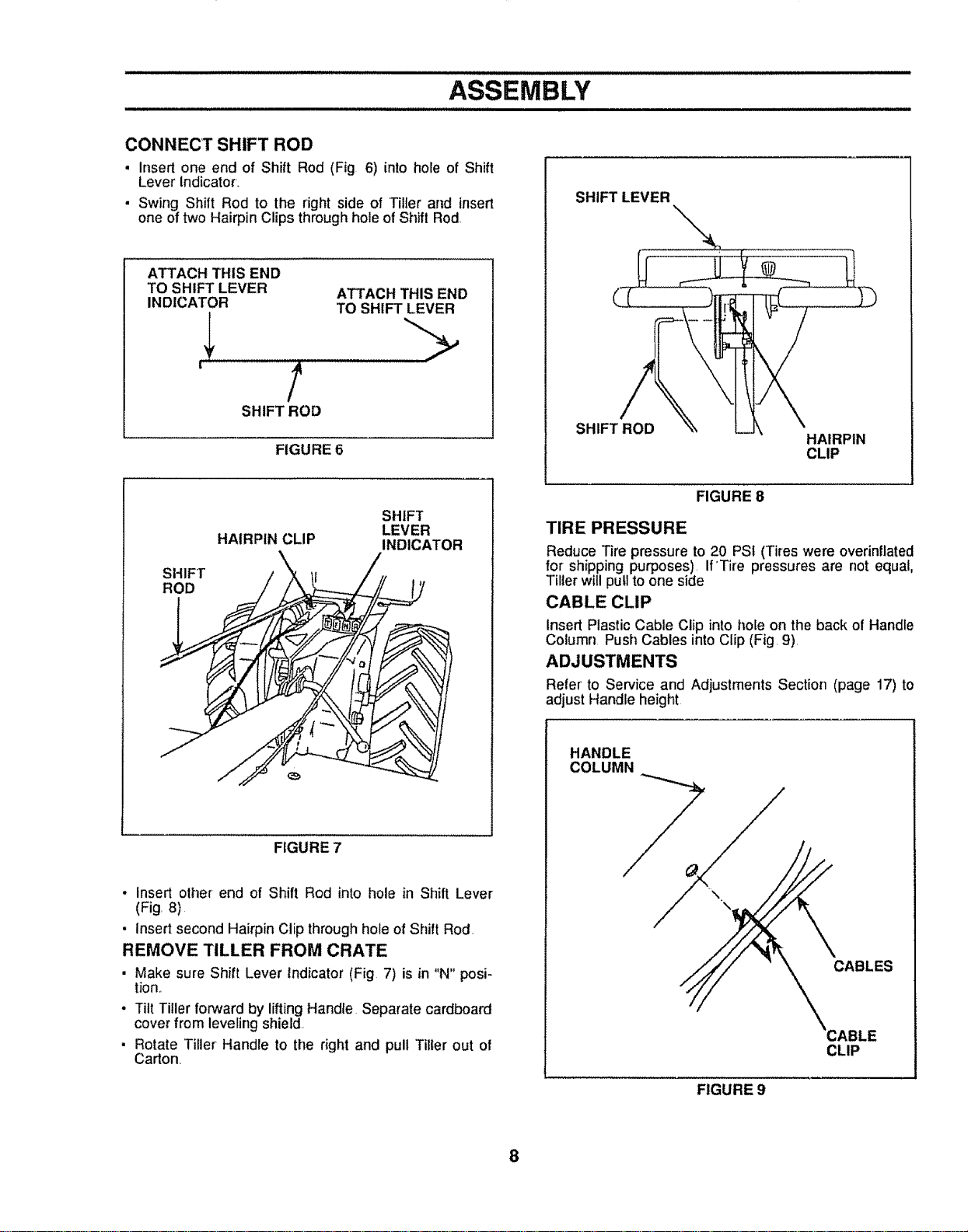
CONNECT SHIFT ROD
, Insert one end of Shift Rod (Fig 6) into hole of Shift
Lever Indicator..
• Swing Shift Rod to the right side of Tiller and insert
one of two Hairpin Clips through hole of Shift Rod.
ATTACH THIS END
TO SHIFT LEVER ATTACH THIS END
INDICATOR TO SHIFT LEVER
' /
SHIFT ROD
FIGURE 6
SHIFT LEVER
SHIFT ROD
HAIRPIN
CLIP
SHIFT
ROD
HAIRPIN CLIP
SHIFT
LEVER
INDICATOR
FIGURE 7
. insert other end of Shift Rod into hole in Shift Lever
(Fig. 8)
• insert second Hairpin Clip throughhole of Shift Rod.
REMOVE TILLER FROM CRATE
• Make sure Shift Lever Indicator (Fig 7) is in "N" posi-
tion._
• Tilt Tiller forward by lifting Handle Separate cardboard
cover from leveling shield.
• Rotate Tiller Handle to the right and pull Tiller out of
Carton
FIGURE 8
TIRE PRESSURE
Reduce Tire pressure to 20 PSI (Tires were overinflated
for shipping purposes). If'Tire pressures are not equal,
Tillerwill pull to one side
CABLE CLIP
Insert Plastic Cable Clip into hoEeon the back of Handle
Column. Push Cables into Clip (Fig. 9)
ADJUSTMENTS
Refer' to Service and Adjustments Section (page 17) to
adjust Handle height
HANDLE
COLUMN
CABLES
CLIP
FIGURE 9
8
- illl i lllU ill LLUIJLIIILILLII,,, " ........... II JlLILll i ,,.,... Illl ILLJLJLJ I,
OPERATION
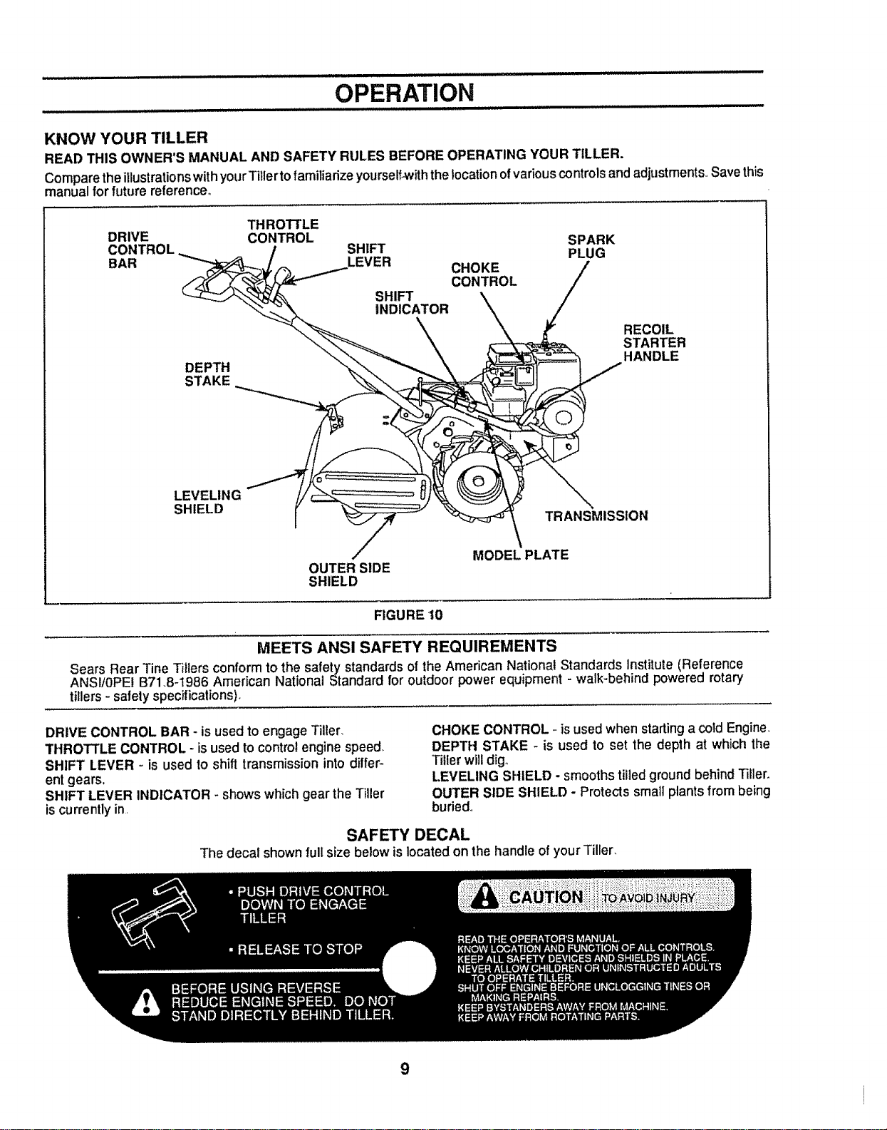
KNOW YOUR TILLER
READ THIS OWNER'S MANUAL AND SAFETY RULES BEFORE OPERATING YOUR TILLER.
ComparetheillustrationswithyourTitiertofamiliadze yourself-withthelocationofvariouscontrolsandadjustments Save this
manual forfuture reference°
THROTTLE
DRIVE CONTROL
DEPTH
STAKE
LEVELING
SHIELD
SPARK
SHIFT PLUG
LEVER CHOKE
CONTROL
SHIFT
INDICATOR
RECOIL
STARTER
HANDLE
TRANSMISSION
OUTER SIDE
SHIELD
MODEL PLATE
FIGURE 10
MEETS ANS! SAFETY REQUIREMENTS
Sears Rear Tine Tillers conform to the safety standards of the American National Standards Institute (Reference
ANSI/0PE! B71.8-1986 American National Standard for outdoor power equipment - walk-behind powered rotary
tillers- safety specifications),
DRIVE CONTROL BAR - isused to engage Tiller,
THROTTLE CONTROL- is used to control engine speed
SHIFT LEVER - is used to shift transmissioninto differ-
ent gears,
SHIFT LEVER INDICATOR - shows which gear the Tiller
is currently in.
CHOKE CONTROL - isused when starting a cold Engine_
DEPTH STAKE - is used to set the depth at which the
Tiller will dig.
LEVELING SHIELD - smooths tilled ground behind Tiller.
OUTER SIDE SHIELD - Protects small plants from being
buried..
SAFETY DECAL
The decal shown full size below is located on the handle of your Tiller.
9
OPERATION
The operationofanyTiller canresultinforeign objectsthrownintotheeyes, whichcanresultinsevere
eye damage. Always wear safety glasses or eye shields before starting your Tiller and while tilling. We
recommend Wide Vision Safety Mask for over the spectacles or standard safety glasses, available at
Sears Retail or Catalog Stores°
HOW TO USE YOUR TILLER
Know how to operate all controlsbeforeadding fuel and
oil or attempting to start Engine. (To stop Engine place
ThrottleControl in STOP position,)
TINE OPERATION -WiTH WHEEL DRIVE
• Always release Drive Control Bar before movingShift
Lever intoanother position,
- Tine movement is achieved by moving Shirt Lever to
"T" positionand engaging Drive ControlBar.,
FORWARD - WHEELS ONLY ! TINES STOPPED
• Release Drive Control Bar and move Shift Lever Indi-
cator to "F" position, Engage Drive Control Bar and
Tiller will move forward
REVERSE - WHEELS ONLY / TINES STOPPED
. DO NOT STAND DIRECTLY BEHIND TILLER
• Release the Drive Control Bar
• Move Throttle Control to "SLOW" position..
• Move Shift Lever Indicator to "R" position,
. Hold Drive Control Bar against the Handle (Fig. 11) to
start Tiller movement.,
DRIVE CONTROL BAR
Z
BAR DISENGAGED _ \
POSITION _ \
FIGURE 11
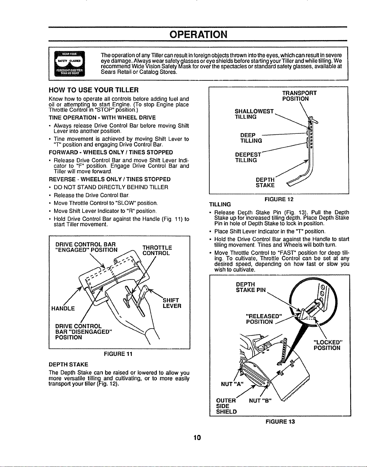
DEPTH STAKE
The Depth Stake can be raised or lowered to allow you
more versatile tilling and cultivating, or to more easily
transportyourtiller (Fig. 12)°
SHALLOWEST
TILLING
TRANSPORT
POSITION
DEEP
TILLING
TILLING
DEPTH
STAKE
FIGURE 12
TILLING
. Release Depth Stake Pin (Fig. 13). Pull the Depth
Stake up for increased tilling depth. Place Depth Stake
Pin in hole of Depth Stake to lockin position.
• Place Shift Lever Indicator in the "T" position..
• Hold the Drive Control Bar against the Handle to start
tilling movement. Tines and Wheels will both turn.,
. Move Throttle Control to "FAST" position for deep till-
ing. To cultivate, Throttle Control can be set at any
desired speed, depending on how fast or slow you
wish to cultivate.
DEPTH
STAKE PIN
"RELEASED"
POSITION
"LOCKED"
POSITION
NUT "A"
OUTER
SIDE
SHIELD
NUT "B"
FIGURE 13
10
OPERATION
STOPPING TINES AND ENGINE
. TILLER MOVEMENT AND TINES WILL STOP WHEN
DRIVE CONTROL BAR iS RELEASED.
• Move Shift Lever Indicator to "N" Neutral position.,
• To stop Engine, move Throttle Control to "STOP" posi-
tion.
TURNING
• Release the Drive Contro! Bar.
• MoveThrottle Control to "SLOW" speed,
. Place Shift Lever Indicator in the "F" Forward position.
Tines will not turn,
• Lift Handle to raise Tines out of ground,.
• Swing the Handle in the opposite direction you wish to
turn, being careful to keep feet and legs away from
Tines,,
• When you have completed your turn-around, release
the Drive Control Bar and lower Handle., Place Shift
Lever in "T" positionand move Throttle Control to de-
sired speed, To begin tilling, hold Drive Control Bar
against the Handle.,
OUTER SIDE SHIELDS
The front of the Outer Side Shields are slotted so that
they can be raised for deep tilling and lowered for shal-
low tilling to protect small plants from being buried.
Loosen Nut "A" in slot and Nut "B" (Fig. 13). Move Shield
to desired position (both sides)., Retighten nuts.
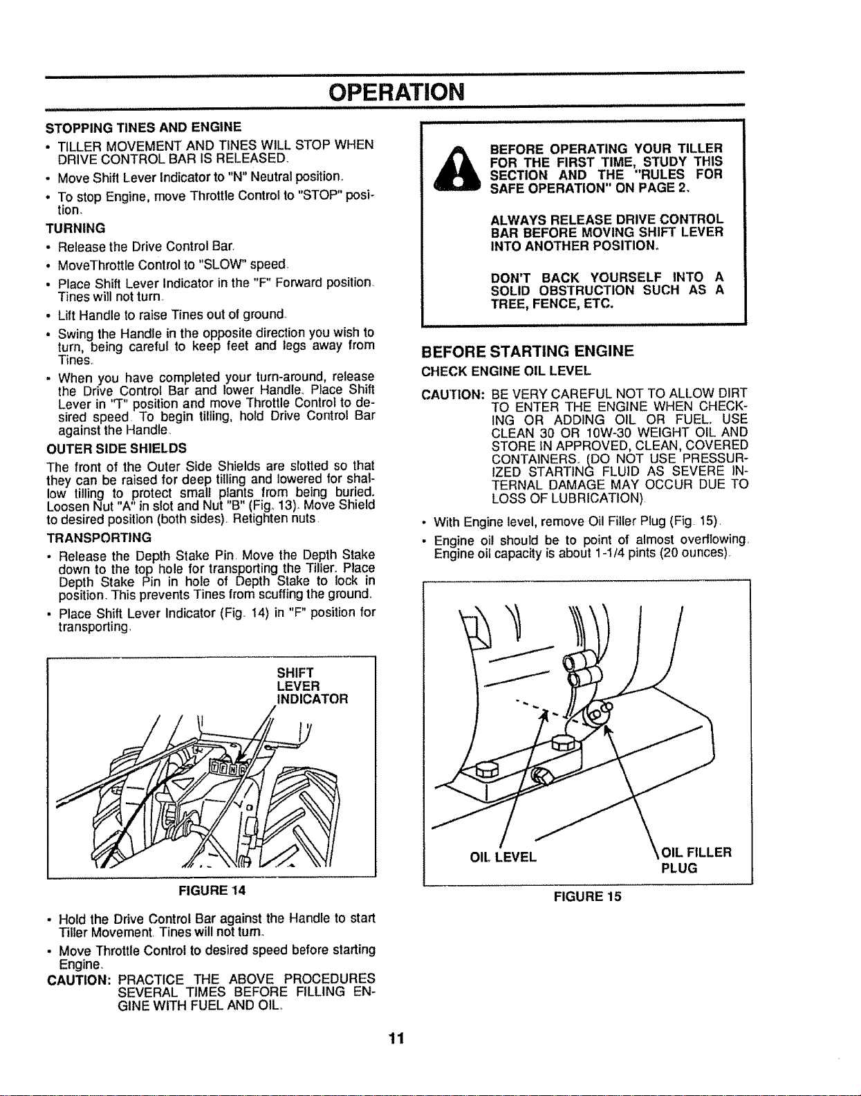
TRANSPORTING
. Release the Depth Stake Pin, Move the Depth Stake
down to the top hole for transporting the Tiller. Place
Depth Stake Pin in hole of Depth Stake to lock in
position. This prevents Tines from scuffing the ground,,
• Place Shift Lever Indicator (Fig° 14) in "F" position for
transporting,
SHIFT
LEVER
INDICATOR
FIGURE 14
• Hold the Drive Control Bar against the Handle to start
Tiller Movement, Tines will not turn
• Move Throttle Control to desired speed before slarting
Engine.
CAUTION: PRACTICE THE ABOVE PROCEDURES
SEVERAL TIMES BEFORE FILLING EN-
GINE WITH FUEL AND OIL,,
BEFORE OPERATING YOUR TILLER
FOR THE FIRST TIME, STUDY THIS
SECTION AND THE "RULES FOR
SAFE OPERATION" ON PAGE 2,
ALWAYS RELEASE DRIVE CONTROL
BAR BEFORE MOVING SHIFT LEVER
INTO ANOTHER POSITION°
DON'T BACK YOURSELF INTO A
SOLID OBSTRUCTION SUCH AS A
TREE, FENCE, ETC.
BEFORE STARTING ENGINE
CHECK ENGINE OIL LEVEL
CAUTION: BE VERY CAREFUL NOT TO ALLOW DIRT
TO ENTER THE ENGINE WHEN CHECK-
ING OR ADDING OIL OR FUEL. USE
CLEAN 30 OR 10W-30 WEIGHT OIL AND
STORE IN APPROVED, CLEAN, COVERED
CONTAINERS,, (DO NOT USE PRESSUR-
IZED STARTING FLUID AS SEVERE IN-
TERNAL DAMAGE MAY OCCUR DUE TO
LOSS OF LUBRICATION)
• With Engine level, remove Oil Filler Plug (Fig 15),
• Engine oil should be to point of almost overttowing,
Engine oil capacity is about 1-1/4 pints (20 ounces),
OIL LEVEL OIL FILLER
PLUG
FIGURE 15
11
OPERATION
H,
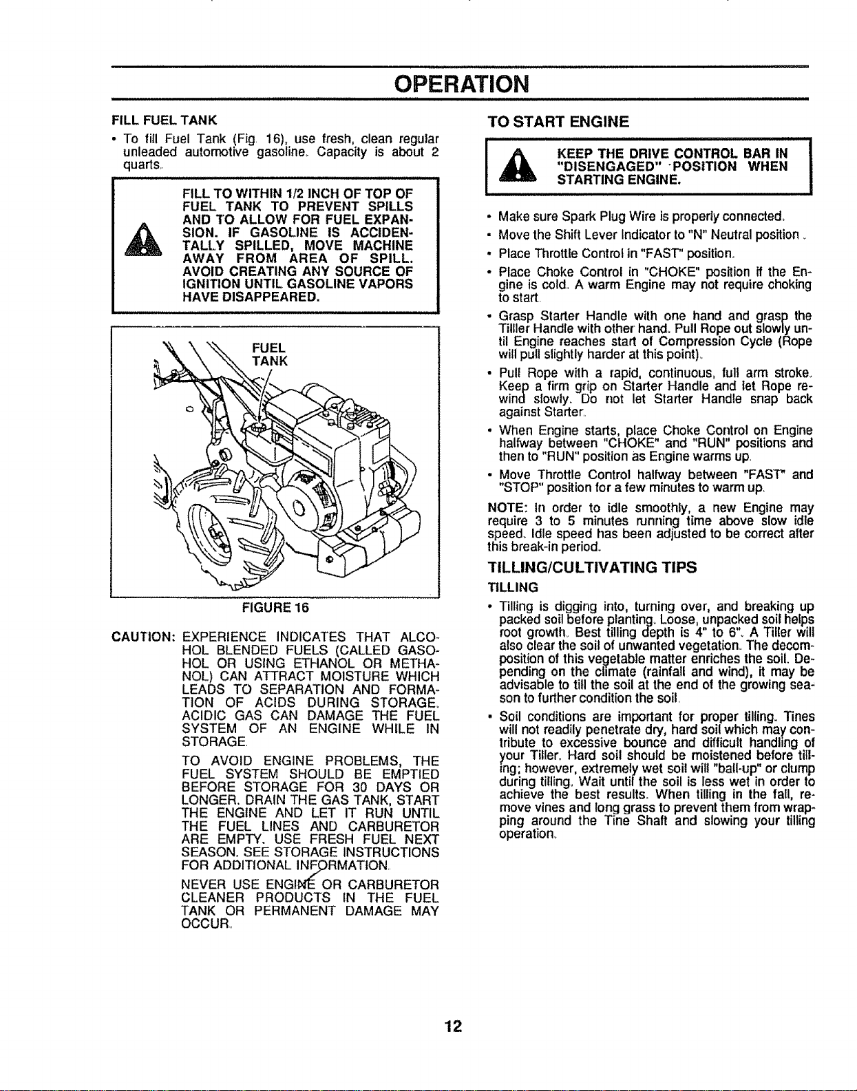
FILL FUEL TANK
• TO fill Fuel Tank (Fig 16), use fresh, clean regular
unleaded automotive gasoline Capacity is about 2
quarts_
FILL TO WITHIN 1/2 INCH OF TOP OF
FUEL TANK TO PREVENT SPILLS
AND TO ALLOW FOR FUEL EXPAN-
SION. IF GASOLINE IS ACCIDEN-
TALLY SPILLED, MOVE MACHINE
AWAY FROM AREA OF SPILL.
AVOID CREATING ANY SOURCE OF
IGNITION UNTIL GASOLINE VAPORS
HAVE DISAPPEARED.
FUEL
TANK
CAUTION:
FIGURE 16
EXPERIENCE INDICATES THAT ALCO-
HOL BLENDED FUELS (CALLED GASO-
HOL OR USING ETHANOL OR METHA-
NOL) CAN ATTRACT MOISTURE WHICH
LEADS TO SEPARATION AND FORMA-
TION OF ACIDS DURING STORAGE.
ACIDIC GAS CAN DAMAGE THE FUEL
SYSTEM OF AN ENGINE WHILE IN
STORAGE
TO AVOID ENGINE PROBLEMS, THE
FUEL SYSTEM SHOULD BE EMPTIED
BEFORE STORAGE FOR 30 DAYS OR
LONGER. DRAIN THE GAS TANK, START
THE ENGINE AND LET IT RUN UNTIL
THE FUEL LINES AND CARBURETOR
ARE EMPTY. USE FRESH FUEL NEXT
SEASON. SEE STORAGE INSTRUCTIONS
FOR _RMATtON
ADDITIONAL
NEVER USE ENGI OR CARBURETOR
CLEANER PRODUCTS iN THE FUEL
TANK OR PERMANENT DAMAGE MAY
OCCUR
TO START ENGINE
KEEP THE DRIVE CONTROL BAR IN
"DISENGAGED" POSITION WHEN
STARTING ENGINE.
iu
. Make sure Spark Plug Wire isproperly connected.
• Move the Shift Lever Indicator to"N" Neutral position,
. Place Throttle Control in "FAST" position.
o Place Choke Control in "CHOKE" position if the En-
gine is cold, A warm Engine may not require choking
to start
• Grasp Starter Handle with one hand and grasp the
Tilller Handle with other hand. Pull Rope out slowly un-
til Engine reaches start of Compression Cycle (Rope
will pull slightly harder at this point)_
• Pull Rope with a rapid, continuous, full arm stroker
Keep a firm grip on Starter Handle and let Rope re-
wine slowly_ Do not let Starter Handle snap back
against Starter'
. When Engine start,s, place, Choke Control on Engine
halfway between CHOKE and "RUN" positions and
then to "RUN" position as Engine warms up
• Move Throttle Control halfway between "FAST" and
"STOP" position for a few minutes to warm up.
NOTE: tn order to idle smoothly, a new Engine may
require 3 to 5 minutes running time above slow idle
speed. Idle speed has been adjusted to be correct after
this break-in period.
TILLING/CULTIVATING TIPS
TILLING
Tilling is digging into, turning over', and breaking up
packed soil before planting_ Loose, unpacked soil helps
root growth_ Best tilling depth is 4" to 6'L A Tiller will
also clear the soil of unwanted vegetation, The decom-
position of this ve._etable matter enriches the soil. De-
pending on the chmate (rainfall and wind), it may be
advisable to till the soil at the end of the growing sea.
son to further condition the soil
Soil conditionsare important for proper tilling."13nes
willnot readily penetrate dry, hard soilwhich may con-
tribute to excessive bounce and difficult handlingof
)tour Titler_Hard soil should be moistened before till-
ing; however, extremely wet soilwill"ball-up"or clump
during tilling,Wait untilthe soil is less wet in order to
achieve the best results° When tilling in the fall, re-
move vines and longgrass to preventthem from wrap-
ping around the Tine Shaft and slowing your tilling
operation.
12
OPERATION
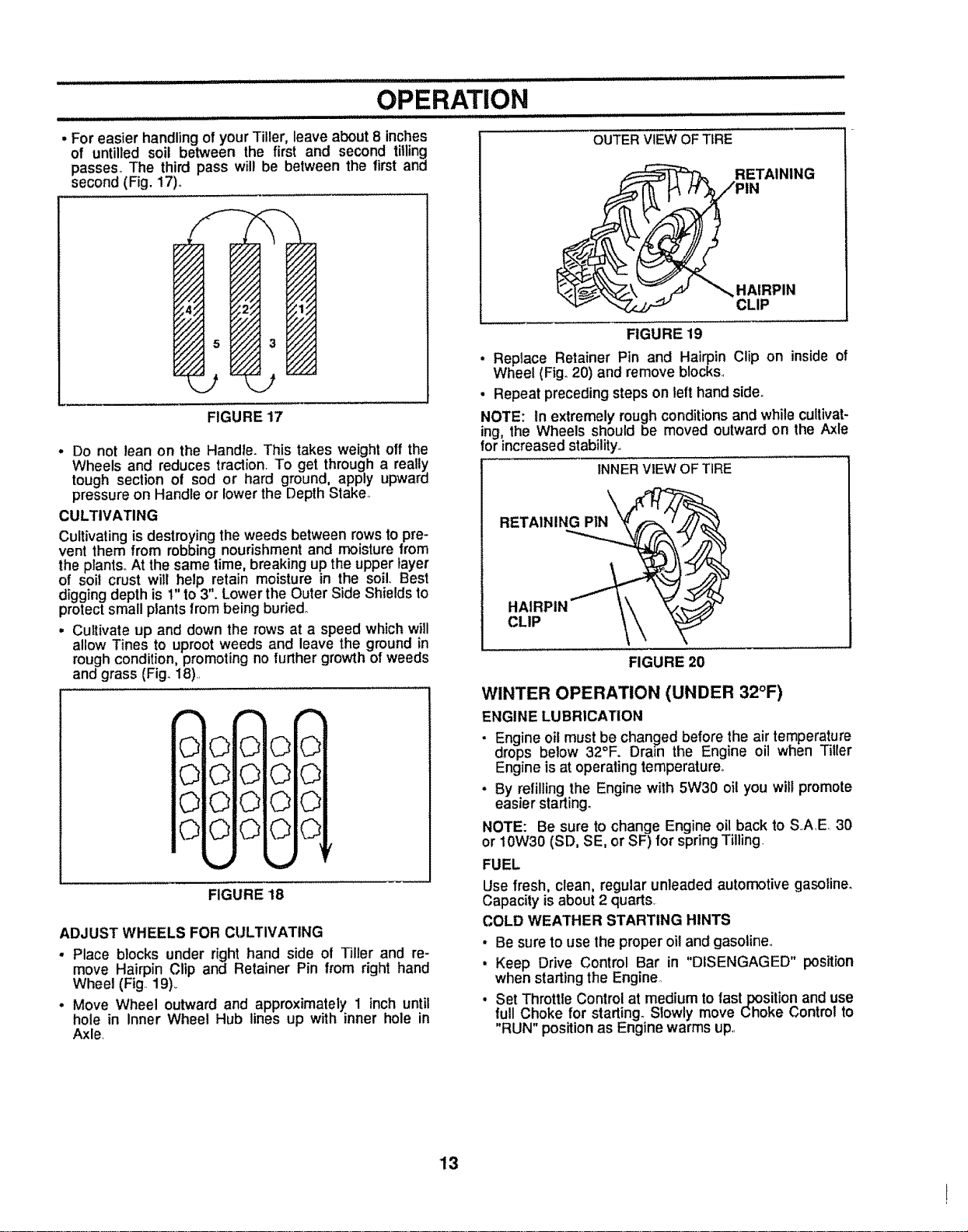
. For easier handling of your Tiller, leave about 8 inches
of untilled soil between the first and second tilling
passes. The third pass will be between the first and
second (Fig. 17).
OUTERVIEWOFTIRE
_ _ ,_ _'_ HAIRPIN
CLIP
FIGURE 17
• Do not lean on the Handle. This takes weight off the
Wheels and reduces traction. To get through a really
tough section of sod or hard ground, apply upward
pressure on Handle or lower the Depth Stake,.
CULTIVATING
Cultivating is destroying the weeds between rows to pre-
vent them from robbing nourishment and moisture from
the plants,.At the same time, breaking up the upper layer
of soil crust will help retain moisture in the soil. Best
digging depth is 1" to3". Lower the Outer Side Shields to
protect small plants from being buried_
• Cultivate up and down the rows at a speed which will
allow Tines to uproot weeds and leave the ground in
rough condition, promoting no further growth of weeds
and grass (Fig. 18).
0
0
0
0
°'°oi
0
O oO
O!
O
O
O
0
FIGURE 18
ADJUST WHEELS FOR CULTIVATING
• Place blocks under right hand side of Tiller and re-
move Hairpin Clip and Retainer Pin from right hand
Wheel (Fig..19)._
• Move Wheel outward and approximately 1 inch until
hole in Inner Wheel Hub lines up with inner hole in
Axle.
FIGURE 19
• Replace Retainer Pin and Hairpin Clip on inside of
Wheel (Fig..20) and remove blocks..
. Repeat precedingsteps on left hand side.
NOTE: In extremely roughconditionsand whilecultivat-
ing, the Wheels should be moved outward on the Axle
for increasedstability_
INNERVIEW OFTIRE
RETAINI
HAIRPIN ""I- \'\ _._
CLIP \',
FIGURE 20
WINTER OPERATION (UNDER 32°F)
ENGINE LUBRICATION
• Engine oilmust be chan_ed before the air temperature
drops below 32°F. Dram the Engine oil when Tiller
Engine is at operatingtemperature°
• By refillingthe Engine with 5W30 oil you will promote
easier starting,
NOTE: Be sure to change Engine oil back to S.AE 30
or 10W30 (SD, SE, or SF) for springTilling,
FUEL
Use fresh, clean, regular unleaded automotive gasoline,
Capacity is about 2 quarts,
COLD WEATHER STARTING HINTS
, Be sure to use the proper oil and gasoline..
• Keep Drive Control Bar in "DISENGAGED" position
when starting the Engine
• Set Throttle Control at medium to fast position and use
full Choke for starting_ Slowly move Choke Control to
"RUN" position as Engine warms up,.
13
i, illllllllllllii i i i ii i i i i i iillllll
MAINTENANCE
i ............
DISCONNECT SPARK PLUG WIRE
FROM SPARK PLUG BEFORE PER-
FORMING ANY MAINTENANCE (EX*
CEPT CARBURETOR ADJUSTMENT )
TO PREVENT ACCIDENTAL START-
ING OF ENGINE.
PREVENT FIRES! KEEP THE ENGINE
FREE OF GRASS, LEAVES, SPILLED
OIL, OR FUEL. REMOVE FUEL FROM
TANK BEFORE TIPPING UNIT FOR
MAINTENANCE. CLEAN MUFFLER
AREA OF ALL GRASS, DIRT, AND DE-
BRIS.
DO NOT TOUCH HOT MUFFLER OR
CYLINDER FINS AS CONTACT MAY
CAUSE BURNS.
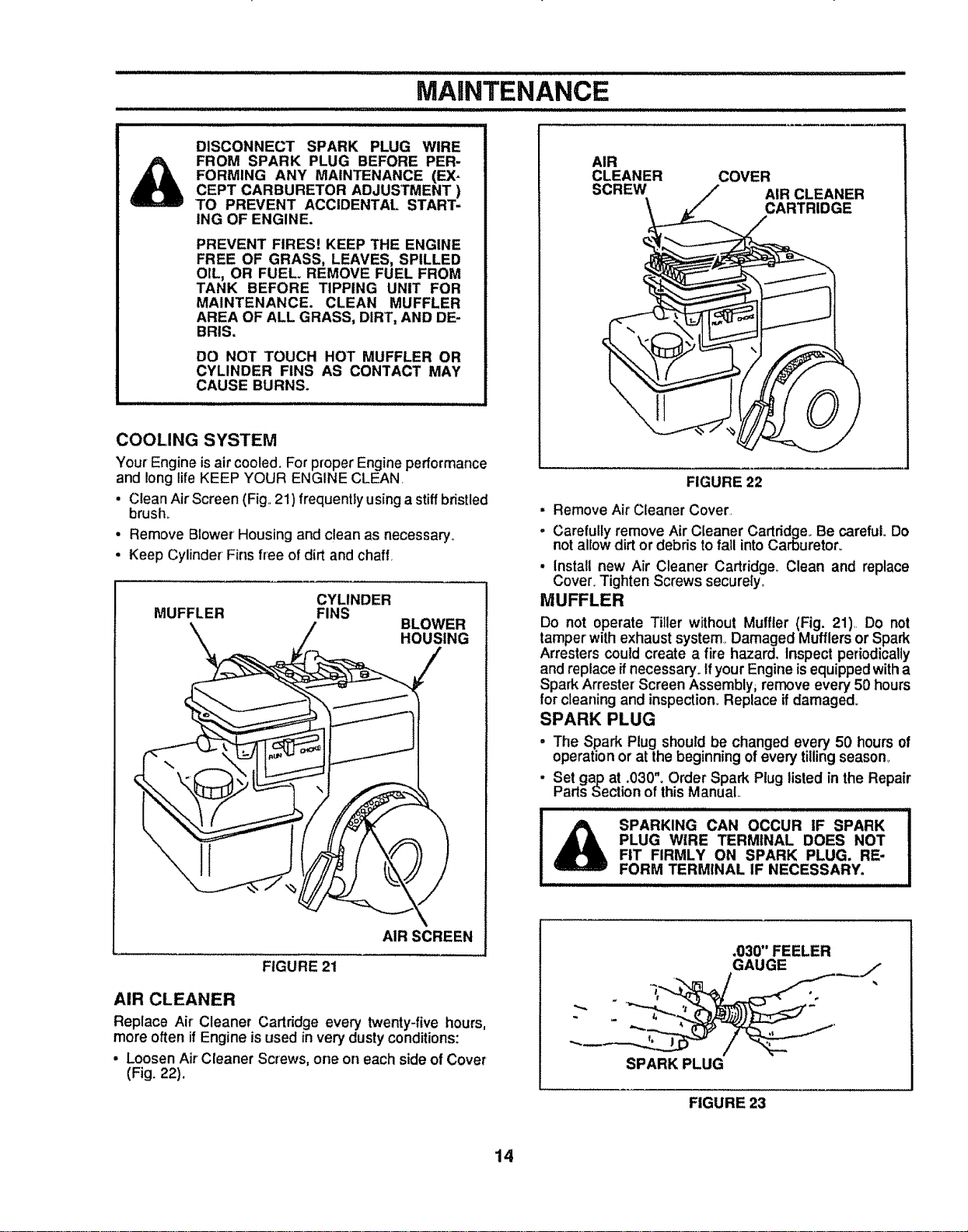
COOLING SYSTEM
Your Engine isair cooled. For proper Engine performance
and long lifeKEEP YOUR ENGINE CLEAN,
• Clean Air Screen (Fig,.21) frequently using a stiff bristled
brush
• Remove Blower' Housing and clean as necessary,,
. Keep Cylinder Fins free of dirt and chaff,
BLOWER
HOUSING
CYLINDER
MUFFLER FINS
AIR SCREEN
FIGURE 21
AIR CLEANER
Replace Air Cleaner Cartridge every twenty-five hours,
more often if Engine isused in very dusty conditions:
• Loosen Air Cleaner Screws, one on each side of Cover
(Fig. 22),
AIR
CLEANER
SCREW
COVER
AIR CLEANER
CARTRIDGE
FIGURE 22
• Remove Air Cleaner Cover,
- Carefully remove Air Cleaner Cartridge° Be careful. Do
not allow dirt or debris to fail into Carburetor.
• Install new Air Cleaner Cartridge_ Clean and replace
Cover, Tighten Screws secureiy_
MUFFLER
Do not operate Tiller without Muffler (Fig. 21),, Do not
tamper with exhaust system, Damaged Mufflers or Spark
Arresters could create a fire hazard. Inspect periodically
and replace _fnecessary. If your Engine is equipped with a
Spark Arrester Screen Assembly, remove every 50 hours
for cleaning and inspection_ Replace ifdamaged.
SPARK PLUG
. The Spark Plug should be changed every 50 hours of
operation or at the beginning of every tilling season_
. Set gap at .030". Order Spark Plug listedin the Repair
Parts Section ofthis Manual
SPARKING CAN OCCUR IF SPARK
PLUG WIRE TERMINAL DOES NOT
FIT FIRMLY ON SPARK PLUG, RE-
FORM TERMINALIF NECESSARY.
.03_'FEELER
GAUGE
SPARK PLUG
FIGURE 23
14
MAINTENANCE
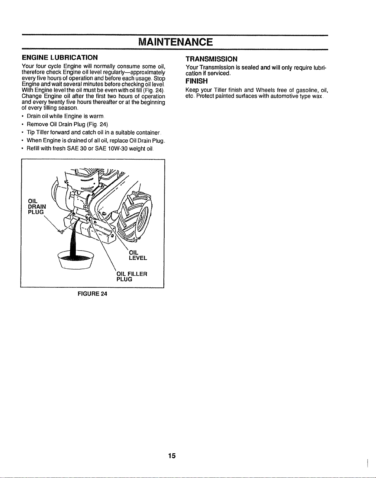
ENGINE LUBRICATION
Your four cycle Engine will normally consume some oil,
therefore check Engine oil level regularly--approximately
every five hours of operation and before each usage. Stop
Engine and wait several minutes before checking oii level,
With Engine level the oil must be even with oil fill(Fig. 24),
Change Engine oil after the first two hours of operation
and every twenty five hours thereafter or at the beginning
of every tilling season.
• Drain oil while Engine is warm,
• Remove Oil Drain Ptug (Fig 24)
. T_pTiller forwardand catch oil in a suitable container,
• When Engine isdrained of all oil, replace Oil Drain Ptugo
• Refill with fresh SAE 30 or SAE 10W-30 weight oil.
TRANSMISSION
Your Transmissionissealed and will onlyrequire lubri-
cation ifserviced_
FINISH
Keep your Tiller finish and Wheels free of gasoline, oil,
etc_Protectpainted surfaceswith automotive typewax.
OIL
DRAIN
PLUG
OIL
LEVEL
OIL FILLER
PLUG
FIGURE 24
15
................................. ,,,,,,,,,,,
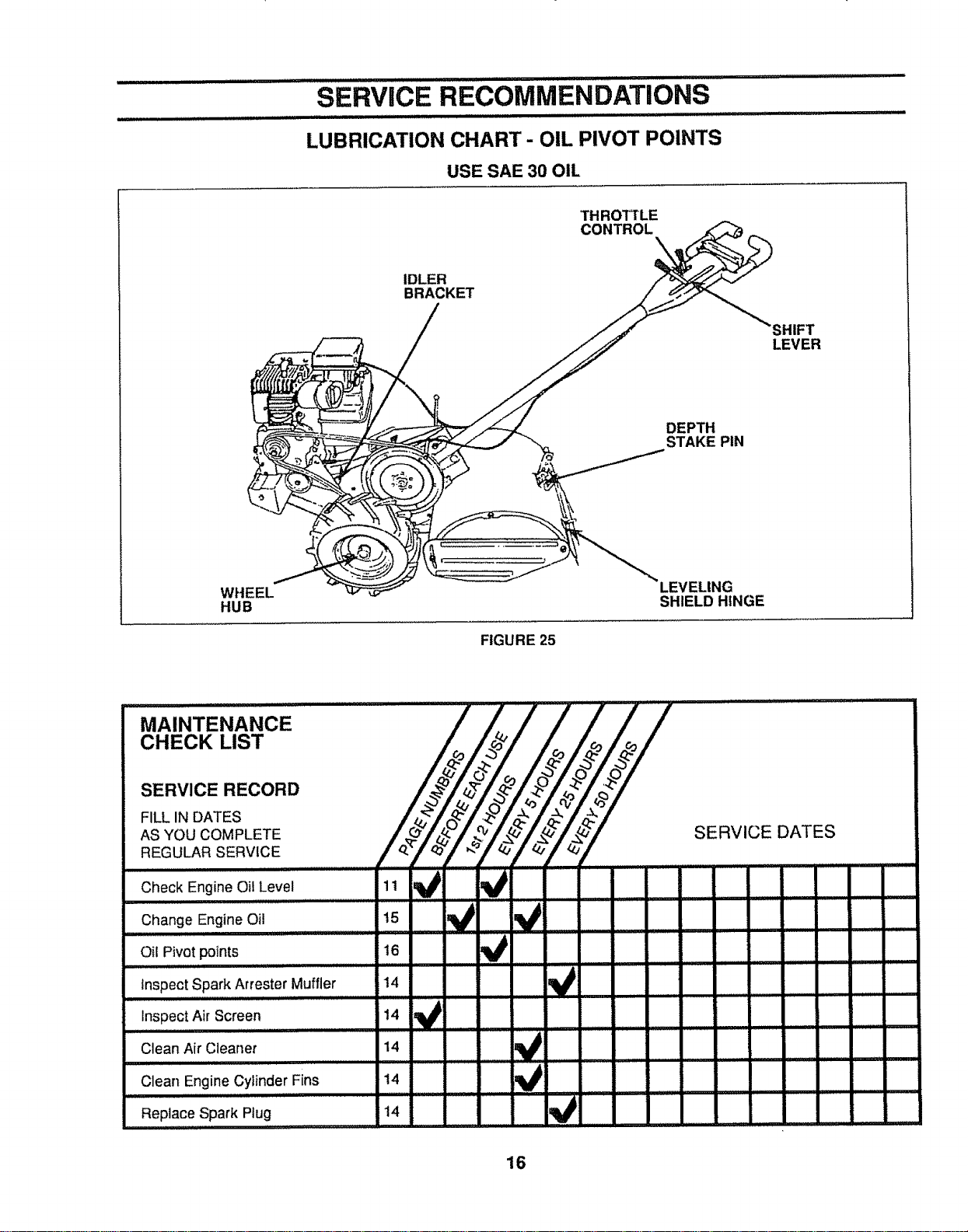
SERVICE RECOMMENDATIONS
LUBRICATION CHART- OIL PIVOT POINTS
USE SAE 30 OIL
TH ROIRLE
CONTROL
IDLER
BRACKET
SHIFT
LEVER
DEPTH
STAKE PIN
WHEEL
HUB
FIGURE 25
SHIELD HINGE
IH Ill NN
MAINTENANCE
CHECK LIST
SERVICE RECORD
FILL IN DATES
AS YOU COMPLETE
REGULAR SERVICE
Check Engine Oil Level
Change Engine Oil
ill Nnl
Oil Pivot points
Inspect Spark Arrester Muffler
inspect Air Screen
Clean Air Cleaner
_Xd_l,, ,,,,,,,,,i....
i
t5
16
14
14
V V
,/
V
SERVICE DATES
Clean Engine Cylinder Fins
llll IN ,HIINI
Replace Spark Plug
14
14
16
SERVICE AND ADJUSTMENTS
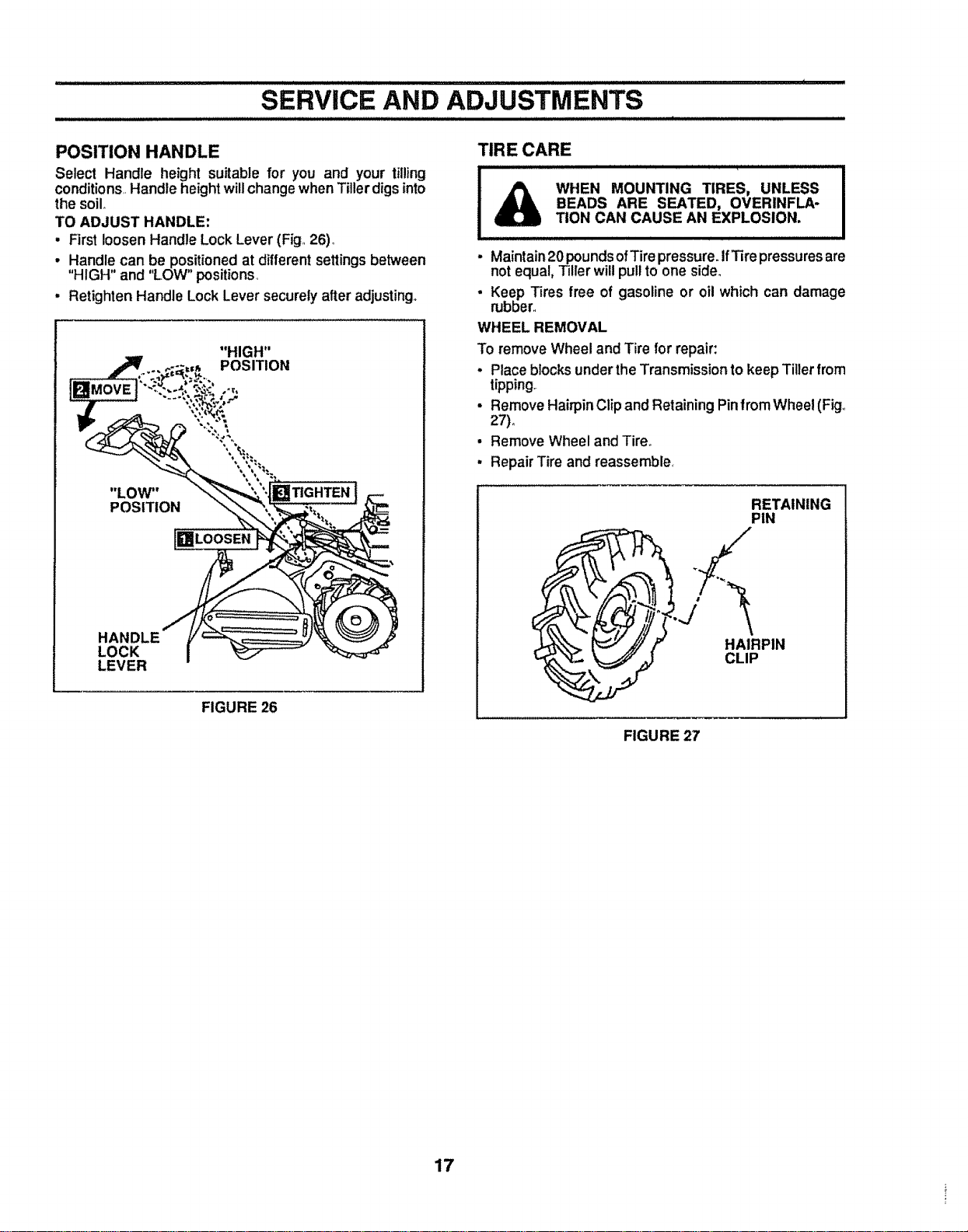
POSITION HANDLE
Select Handle height suitable for you and your tilling
conditions,Handle heightwillchangewhen Tillerdigsinto
the soilo
TO ADJUST HANDLE:
• Firstloosen Handle LockLever (Fig,26),,
• Handle can be positionedat differentsettingsbetween
"HIGH" and "LOW" positions,
• Retighten Handle Lock Lever securely after adjusting°
"HIGH"
POSITION
HANDLE
LOCK
LEVER
FIGURE 26
TIRE CARE
WHEN MOUNTING TIRES, UNLESS
BEADS ARE SEATED, OVERINFLA-
TION CAN CAUSE AN EXPLOSION.
- Maintain 20pounds ofTire pressure. IfTire pressures are
not equal, Tiller will pull to one side.
• Keep Tires free of gasoline or oil which can damage
rubber,,
WHEEL REMOVAL
To remove Wheel and Tire for repair:
• Place blocks under the Transmission to keep Tiller from
tipping°
• Remove Hairpin Clip and Retaining PinfromWheel (Fig.,
27).
" Remove Wheel and Tire,,
• Repair Tire and reassemble,
RETAINING
PIN
FIGURE 27
17
SERVICE AND ADJUSTMENTS
,ll,
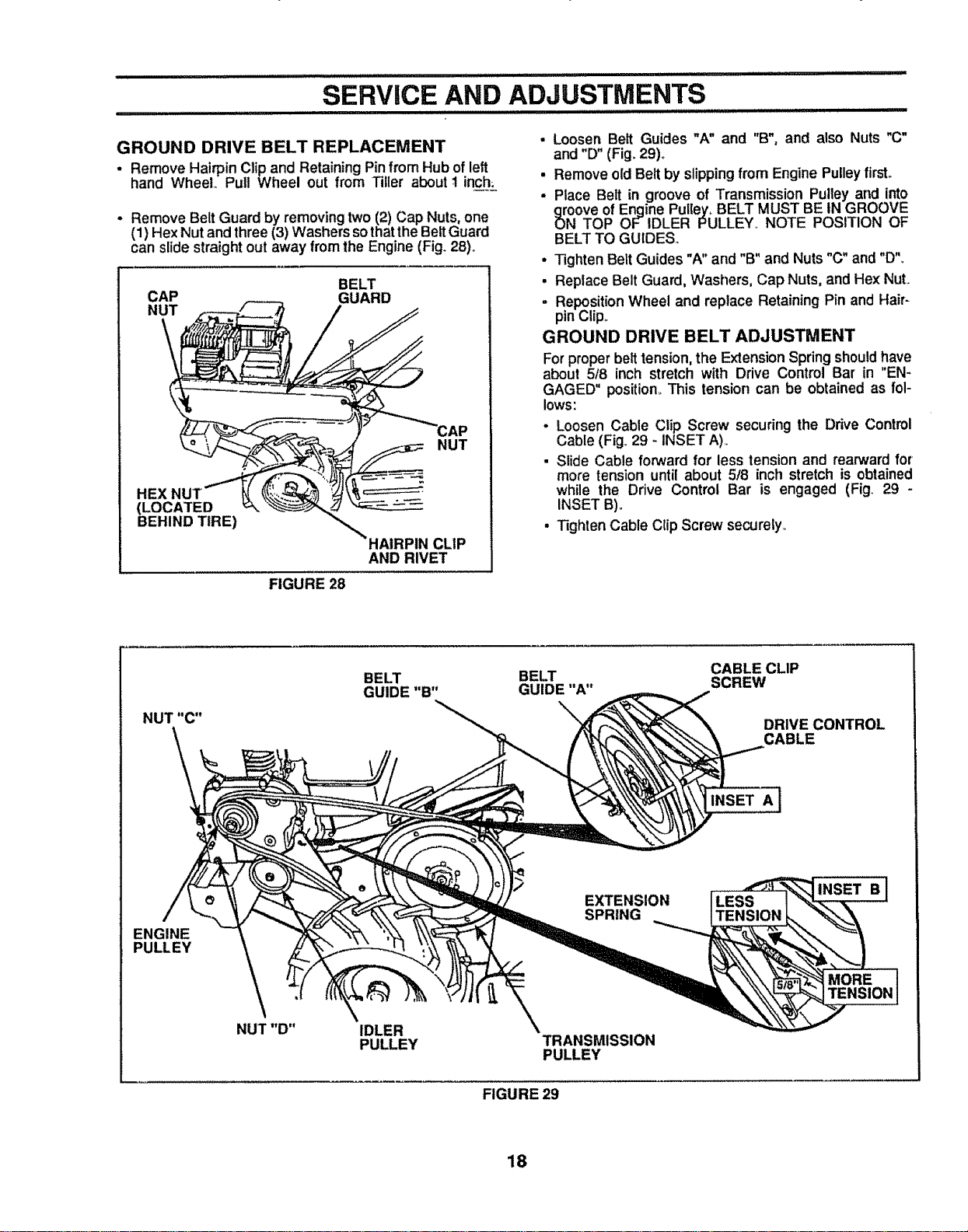
GROUND DRIVE BELT REPLACEMENT
- Remove Hairpin Clip and RetainingPinfrom Hub ofleft
hand Wheel Pull Wheel out from Tiller aboutI inc_h__
- Remove Belt Guard by removing two (2) Cap Nuts, one
(1) Hex Nut and three (3) Washers sothat the Belt Guard
can slide straight out away from the Engine (Fig. 28).
CAP
NUT
BELT
GUARD
HEX
(LOCATED
BEHIND TIRE)
NUT
HAIRPIN CLIP
AND RIVET
• Loosen Belt Guides "A" and "B", and also Nuts "C"
and "D" (Fig. 29)°
• Remove oldBelt by slipping from Engine Pulley firsL
• Place Belt in groove of Transmission Pulley and into
oove of Engine Pulley,rBELT MUST BE tN GROOVE
N TOP OF IDLER PULLEY_ NOTE POSITION OF
BELT TO GUIDES.,
• Tighten Belt Guides "A" and "B" and Nuts "C" and "D".
• Replace Belt Guard, Washers, Cap Nuts, and Hex NuL
- Reposition Wheel and replace Retaining Pin and Hair-
pin Cfip_
GROUND DRIVE BELT ADJUSTMENT
For proper belt tension, the Extension Spring should have
about 518 inch stretch with Drive Control Bar in "EN-
GAGED" position_ This tension can be obtained as fol-
lows:
• Loosen Cable Clip Screw securing the Drive Control
Cable (Fig. 29 - INSET A)..
• Slide Cable forward for less tension and rearward for
more tension until about 5/8 inch stretch is obtained
while the Drive Control Bar is engaged (Fig. 29 -
INSET B)_
• Tighten Cable Clip Screw securely_
FIGURE 28
BELT BELT CABLE CLIP
GUIDE"B" GUIDE"A" SCREW
DRIVE CONTROL
CABLE
INSET A
ENGINE
PULLEY
NUT "D"
\
IDLER
PULLEY
EXTENSION
SPRING
TRANSMISSION
PULLEY
LESS
TENSION
INSET B
MORE
TENSION
FIGURE 29
18
SERVICE AND ADJUSTMENT
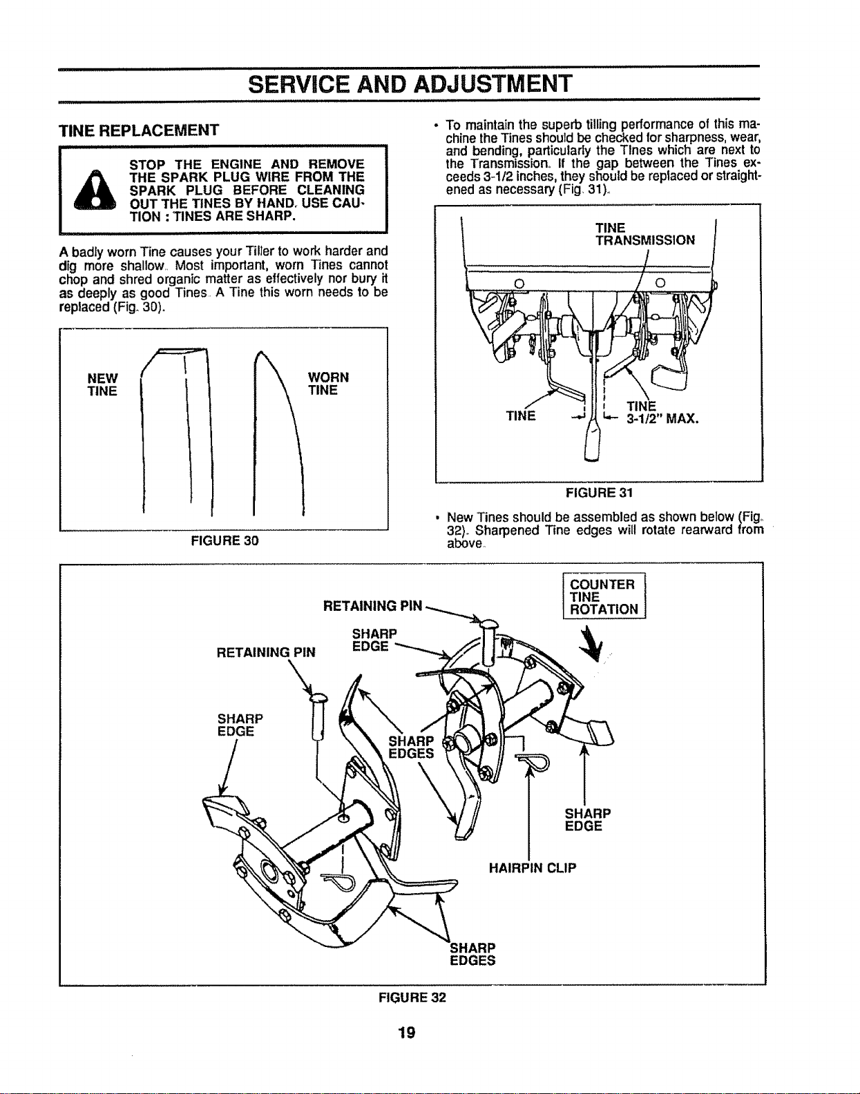
TINE REPLACEMENT
STOP THE ENGINE AND REMOVE
THE SPARK PLUG WIRE FROM THE
SPARK PLUG BEFORE CLEANING
OUT THE TINES BY HAND. USE CAU*
TION : TINES ARE SHARP.
A badly worn Tine causes your Tiller towork harder and
dig more shallow.. Most important, worn Tines cannot
chop and shred organic matter as effectively nor bury it
as deeply as good Tines. A Tine this worn needs to be
replaced (Fig. 30).
NEW
TINE
WORN
TINE
FIGURE 30
• To maintain the superb tillingperformance of this ma-
chine the Tines should be checked forsharpness, wear,
and bending, particularlythe Tlnes which are nextto
the Transmission° If the gap between the Tines ex-
ceeds 3-1/2 inches, they should be replaced or straight-
ened as necessary (Fig 31)4
!_ TINE t
L i,,,io ,, / o
TINE
TI _ 3-1t2" MAX,
FIGURE 31
• New Tines should be assembled as shown below (Fig.
32)° Sharpened "Fine edges will rotate rearward from
above..
RETAINING PIN
SHARP \_
EDGE
RETAINING PIN
SHARP
EDGE
I OUNTER
TINE
ROTATION
SHARP
EDGE
I
HAIRPIN CLIP
SHARP
EDGES
FIGURE 32
19
IIIlUlII
SERVICE AND ADJUSTMENT
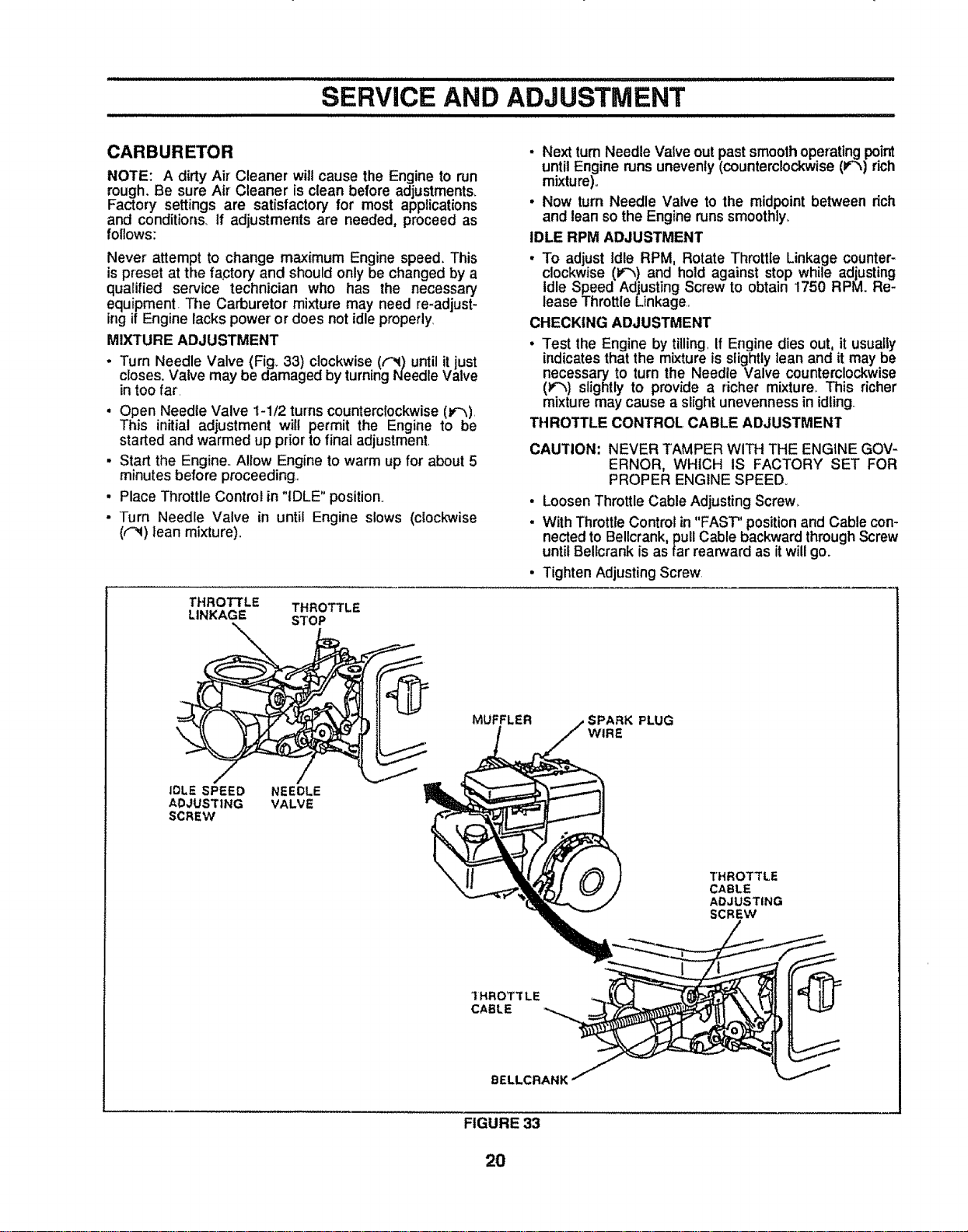
CARBURETOR
NOTE: A dirty Air Cleaner willcause the Engine to run
rough. Be sure Air Cleaner is clean before adjustments_
Factory settings are satisfactory for most applications
and conditions, if adjustments are needed, proceed as
follows:
Never attempt to change maximum Engine speed. This
is preset at the fa,ctory and should only be changed by a
qualified service technician who has the necessary
equipment. The Carburetor mixture may need re-adjust-
ingit Engine lacks power' or does not idle properly,
MIXTURE ADJUSTMENT
. Turn Needle Valve (Fig. 33) clockwise (('_1)until it just
closes. Valve may be damaged by turning Needle Valve
intoo far,
• Open Needle Valve 1-1t2 turnscounterclockwise (J¢'_),
This initial adjustment will permit the Engine to be
started and warmed up prior to final adjustment,
• Start the Engine,. Allow Engine to warm up for about 5
minutes before proceeding,,
. Place Throttle Control in "iDLE" position,
• Turn Needle Valve in until Engine slows (clockwise
((-_) lean mixture).,
THROTTLE THROTTLE
LINKAGE STOP
* Next turnNeedle Valve out past smoothoperatingpoint
untilEngine runsunevenly(counterclockwise(F'_) rich
mixture).
, Now turn Needle Valve to the midpoint between rich
and lean sothe Engine runs smoothly_
IDLE RPM ADJUSTMENT
• To adjust Idle RPM, Rotate Throttle Linkage counter-
clockwise (V'_,)and hold against stop while adjusting
Idle Speed Adjusting Screw to obtain 1750 RPM. Re-
lease Throttle Linkage,,
CHECKING ADJUSTMENT
. Test the Engine by tilling,If Engine dies out, it usually
indicates that the mixture isslightly lean and it may be
necessary to turn the Needle Valve counterclockwise
(_"_,)slightly to provide a richer mixture,. This richer
mixture may cause a slight unevenness in idling..
THROTTLE CONTROL CABLE ADJUSTMENT
CAUTION; NEVER TAMPER WITH THE ENGINE GOV-
ERNOR, WHICH IS FACTORY SET FOR
PROPER ENGINE SPEED°
• Loosen Throttle Cable Adjusting Screw.
. With Throttle Control in"FAST" position and Cable con-
nected to Bellcrank, pull Cable backward through Screw
until Bellcrank is as far rearward as itwill go.
, Tighten Adjusting Screw
MUFFLER ;PARK PLUG
WIRE
IDLE SPEED NEEDLE
ADJUSTING VALVE
SCREW
THROTTLE
CABLE
ADJUSTING
SCREW
9ELLCRANK
FIGURE 33
2O
STORAGE
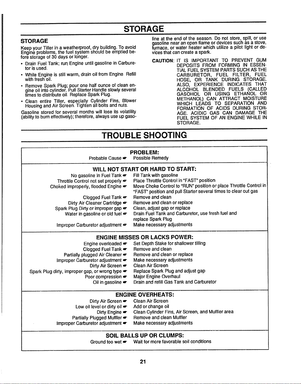
STORAGE
Keep yourTiller in a weatherproof,dry building_To avoid
Engine problems, the fuel system should be emptied be-
fore storage of 30 days or longer°
• Drain Fuel Tank; run Engine until gasoline in Carbure-
tor is used..
. While Engine is still warm, drain oilfrom Engine. Refill
with fresh oilo
- Remove Spark Plug; pour one half ounce of clean en-
gine oil into cylinder. Pull Starter Handle slowly several
times to distribute oil, Replace Spark Plug..
. Clean entire Tiller, especially Cylinder Fins, Blower
Housing and Air Screen..Tighten all bolts and nuts..
Gasoline stored for several months will lose its volatility
(ability to burn effectively); therefore, always use up gaso-
line at the end of the season, Do not store, spill, or use
gasoline near an open flame or devices such as a stove,
furnace, or water heater which utilize a pilot light or de-
vices that can create a spark.
CAUTION: IT IS IMPORTANT TO PREVENT GUM
DEPOSITS FROM FORMING IN ESSEN-
TIAL FUEL SYSTEM PARTS SUCH AS THE
CARBURETOR, FUEL FILTER, FUEL
HOSE, OR TANK DURING STORAGE.
ALSO, EXPERIENCE INDICATES THAT
ALCOHOL BLENDED FUELS (CALLED
GASOHOL OR USING ETHANOL OR
METHANOL) CAN ATTRACT MOISTURE
WHICH LEADS TO SEPARATION AND
FORMATION OF ACIDS DURING STOR-
AGE. ACIDIC GAS CAN DAMAGE THE
FUEL SYSTEM OF AN ENGINE WHILE IN
STORAGE.
TROUBLE SHOOTING
, ,,,,,, ........................................
PROBLEM:
Probable Cause w Possible Remedy
WILL NOT START OR HARD TO START:
No gasoline in FuelTank w' FillTank withgasoline
Throttle Control not set properly
Choked improperly, floodedEngine
Clogged Fuel Tank
Dirty Air Cleaner Cadridge
Spark Plug Dirty or impropergap
Water in gasoline or old fuel
Improper Carburetor adjustment
,=" Place Throttle Control in "FAST" position
=r Move Choke Control to "RUN" position or place Throttle Control in
"FAST" position and pull Starter several times to clear out gas
r Remove and clean
w" Remove and clean or replace
r Clean, adjust gap or replace
w Drain Fuel Tank and Carburetor, use fresh fuel and
replaceSpark Plug
_" Make necessary adjustments
ENGINE MISSES OR LACKS POWER:
Engine overloaded is., Set Depth Stake forshallowertilling
Clogged Fuel Tank
Partially plugged Air Cleaner
Improper Carburetor adjustment
Dirty Air Screen
Spark Plug dirty, improper gap, or wrong type
Poor compression
Oil in gasoline
,r Remove and clean
,=" Remove and clean or replace
,_ Make necessary adjustments
w. Clean Air Screen
,r. Replace Spark Plug and adjust gap
r Major Engine Overhaul
w' Drain and refill Gas Tank and Carburetor
ENGINE OVERHEATS:
Dirty Air Screen r Clean AirScreen
Low oil level or dirty oil or' Add or change oil
Dirty Engine ,,r. Clean Cylinder Fins, Air Screen, and Muffler area
Partially Plugged Muffler =r, Remove and clean Muffler
Improper Carburetor adjustment m., Make necessary adjustments
SOIL BALLS UP OR CLUMPS:
Ground too wet _ Wait for more favorable soit conditions
21

22
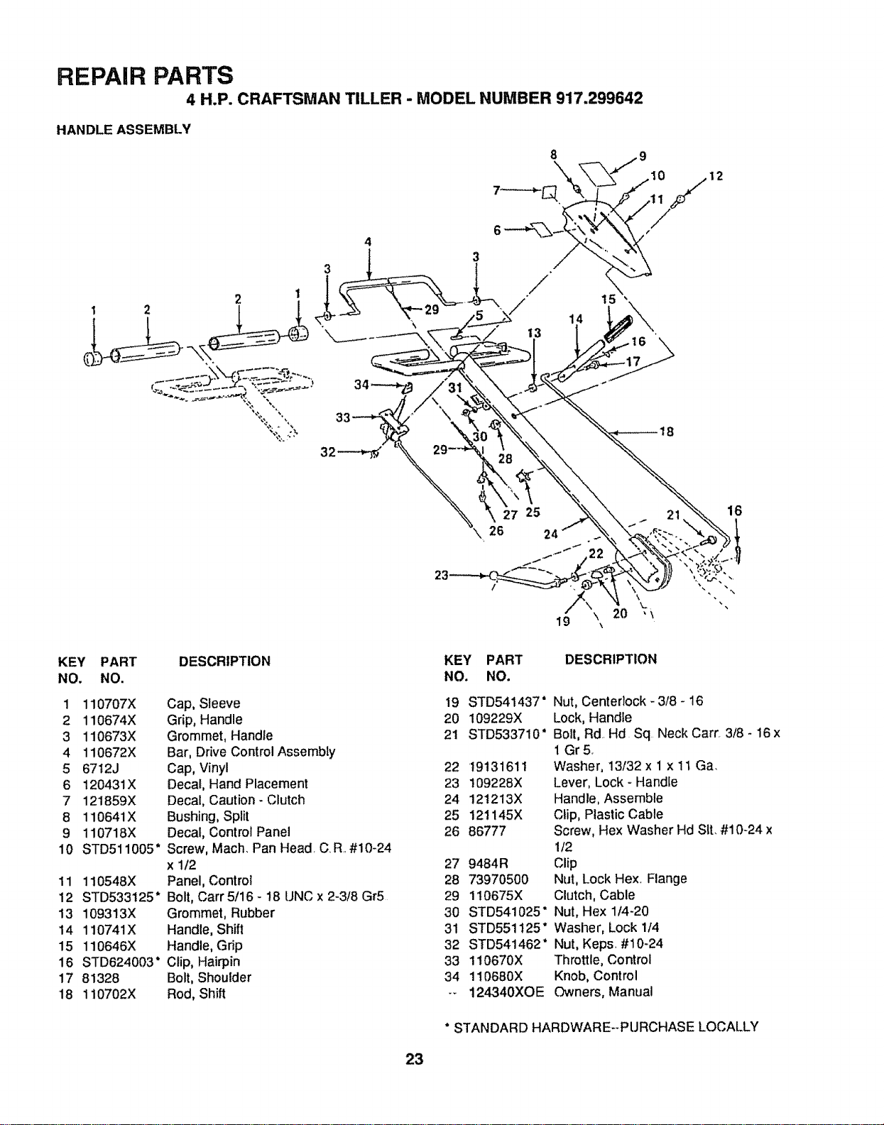
REPAIR PARTS
4 H.P. CRAFTSMAN TILLER - MODEL NUMBER 917.299642
HANDLE ASSEMBLY
12
"%::.',
32---_
26
16
KEY PART
NO, NO.
1 110707X
2 110674X
3 110673X
4 110672X
5 6712J
6 120431X
7 121859X
8 110641X
9 110718X
10 STD511005"
11 110548X
12 STD533125"
13 109313X
14 110741X
15 110646X
16 STD624003"
17 81328
18 110702X
DESCRIPTION
Cap, Sleeve
Grip, Handle
Grommet, Handle
Bar, Drive Control Assembly
Cap, Vinyl
Decal, Hand Placement
Decal, Caution - Clutch
Bushing, Split
Decal, Control Panel
Screw, Mach. Pan Head. C.R..#10-24
x 1/2
Panel, Control
Bolt, Carr 5/16 - 18 UNC x 2-3/8 Gr5
Grommet, Rubber
Handle, Shift
Handle, Grip
Clip, Hairpin
Bolt, Shoulder
Rod, Shift
KEY PART DESCRIPTION
NO. NO.
19 STD541437" Nut, Centedock - 3/8 - 16
20 109229X Lock, Handle
21 STD533710" Bolt, Rd. Hd Sq Neck Carr. 3/8 - 16 x
1 Gr5.
22 19131611 Washer, 13/32 x 1 x 11 Ga,
23 109228X Lever, Lock - Handle
24 121213X Handle, Assemble
25 121145X Clip, Plastic Cable
26 86777 Screw, Hex Washer Hd Sit. #10-24 x
1/2
27 9464R Clip
28 73970500 Nut, Lock Hex, Flange
29 110675X Clutch, Cable
30 STD541025" Nut, Hex 114-20
31 STD551125" Washer, Lock 1/4
32 STD54t462" Nut, Keps. #10-24
33 1t0670X Throttle, Control
34 110680X Knob, Control
-- 124340XOE Owners, Manual
* STANDARD HARDWARE--PURCHASE LOCALLY
23
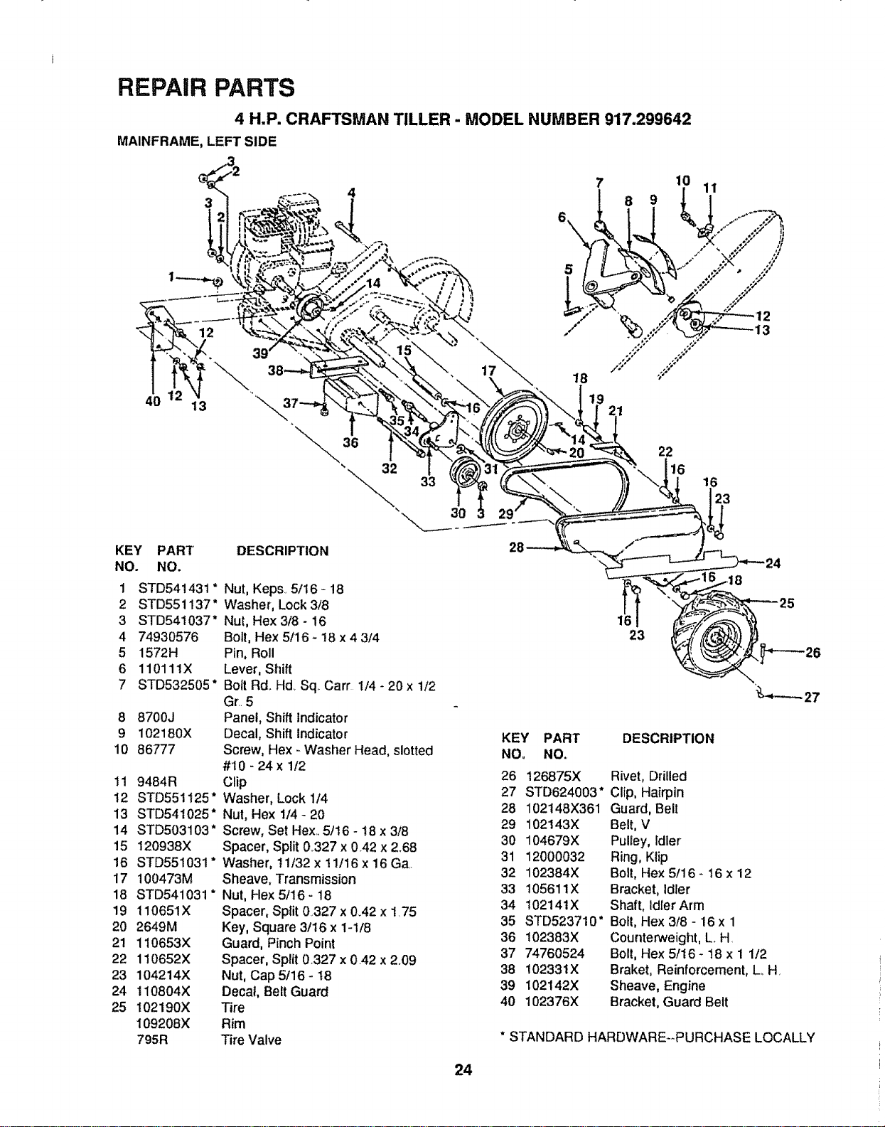
REPAIR PARTS
4 H,P. CRAFTSMAN TILLER - MODEL NUMBER 917.299642
MAINFRAME, LEFT SIDE
3
12
40 13
KEY PART
NO. NO.
1 STD541431 *
2 STD551137"
3 STD541037"
4 74930576
5 1572H
6 110111X
7 STD532505"
8 8700J
9 102180X
10 86777
11 9484R
12 STD551t25"
13 STD541025"
14 STD503103"
15 120938X
16 STD551031"
I7 100473M
18 STD541031 *
19 110651X
20 2649M
21 110653X
22 110652X
23 104214X
24 110804X
25 102190X
109208X
795R
DESCRIPTION
22
16
16
23
Nut, Keps. 5116 - 18
Washer, Lock 3/8
Nut, Hex 3/8 - 16
Bolt, Hex 5116- !8 x 4 3/4
Pin, Roll
Lever, Shift
Bolt Rd..Hd_Sq Cart 1/4 - 20 x 1/2
Gr..5
Panel, Shift Indicator
Decal, Shift indicator
Screw, Hex - Washer Head, slotted
#t 0 - 24 x 1/2
Clip
Washer, Lock 114
Nut, Hex 1/4- 20
Screw, Set Hex. 5/16 - 18 x 3/8
Spacer, Split 0_327x 0.42 x 2.68
Washer, 11/32 x 11/16 x 16 Ga..
Sheave, Transmission
Nut, Hex 5/16 - 18
Spacer, Split 0327 x 0.42 x 1.75
Key, Square 3!16 x 1-1/8
Guard, Pinch Point
Spacer, Split 0.327 x 0.42 x 2.09
Nut, Cap 5/16 - 18
Decal, Belt Guard
Tire
Rim
Tire Valve
16
23
KEY PART DESCRIPTION
NO, NOo
26 126875X Rivet, Drilled
27 STD624003" Clip, Hairpin
28 102148X361 Guard, Belt
29 102143X Belt, V
30 104679X Pulley, Idler
31 12000032 Ring, Klip
32 102384X Bolt, Hex 5/16 - 16 x 12
33 105611X Bracket, Idler
34 102141X Shaft, idlerArm
35 STD523710' Bolt, Hex 3/8 - 16 x 1
36 102383X CourlteP_veight,L, H.
37 74760524 Bolt, Hex 5/16 - 18 x 1 1/2
38 102331X Braket, Reinforcement, L. H,
39 102142X Sheave, Engine
40 102376X Bracket, Guard Belt
* STANDARD HARDWARE--PURCHASE LOCALLY
24
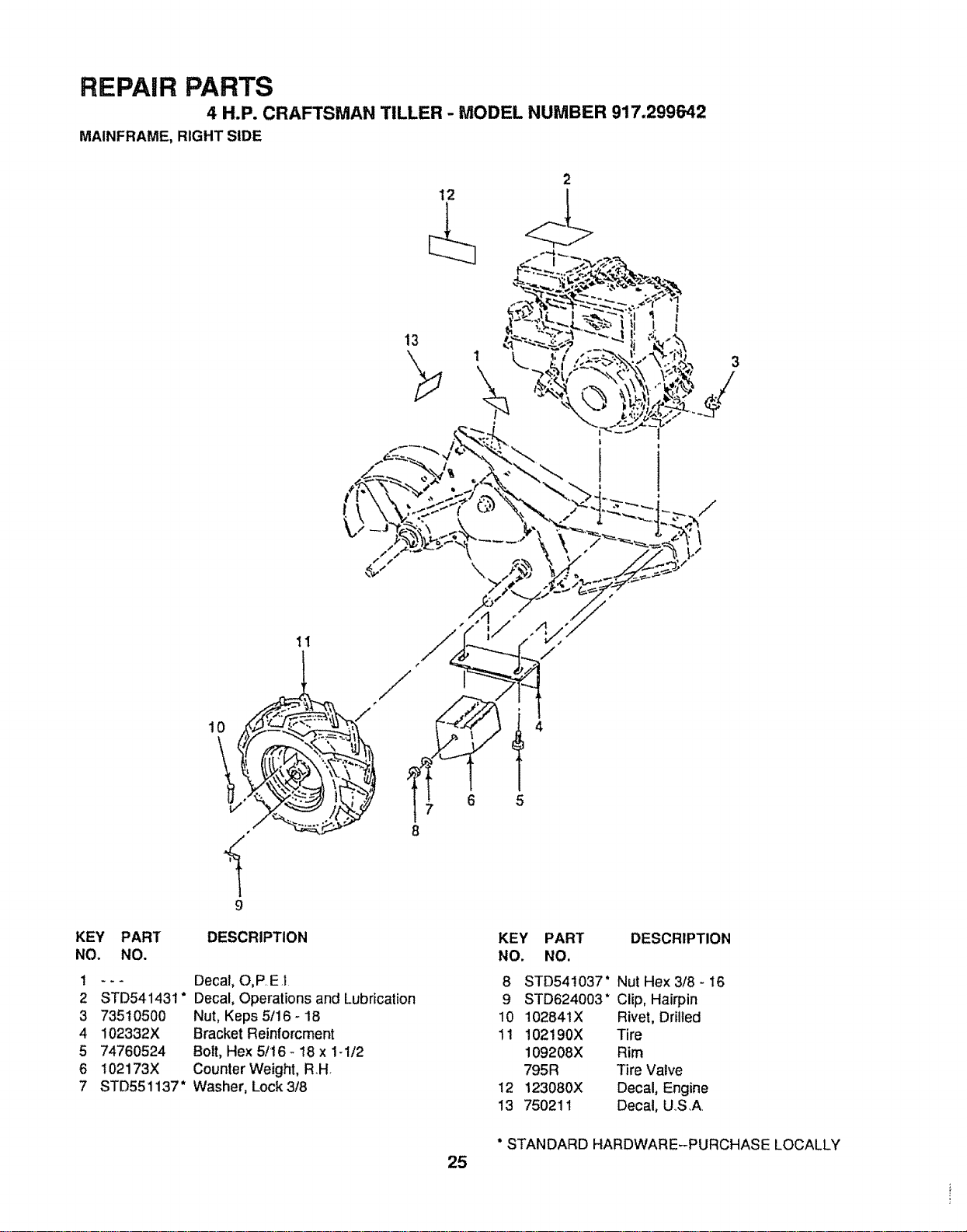
REPAIR PARTS
4 H.P. CRAFTSMAN TILLER - MODEL NUMBER 917.299642
MAINFRAME, RIGHT SIDE
2
12
13
9
KEY PART DESCRIPTION
NO, NO.
t --- Decal, O,P.E.I
2 STD541431" Decal, Operationsand Lubrication
3 73510500 Nut, Keps 5/16 - 1B
4 102332X Bracket Reinforcment
5 74760524 Bolt, Hex 5/I6- 18 x 1-1/2
6 102173X Counter Weight, RH
7 STD551137" Washer, Lock 3/8
25
/
5
KEY
NO.
8
9
10
11
12
13
PART DESCRIPTION
NO.
STD541037" Nut Hex 3/8 - 16
STD624003" Clip, Hairpin
102841X Rivet, Drilled
102! 90X Tire
109208X Rim
795R Tire Valve
123080X Decal, Engine
750211 Decal, U,.S.A.
* STANDARD HARDWARE--PURCHASE LOCALLY
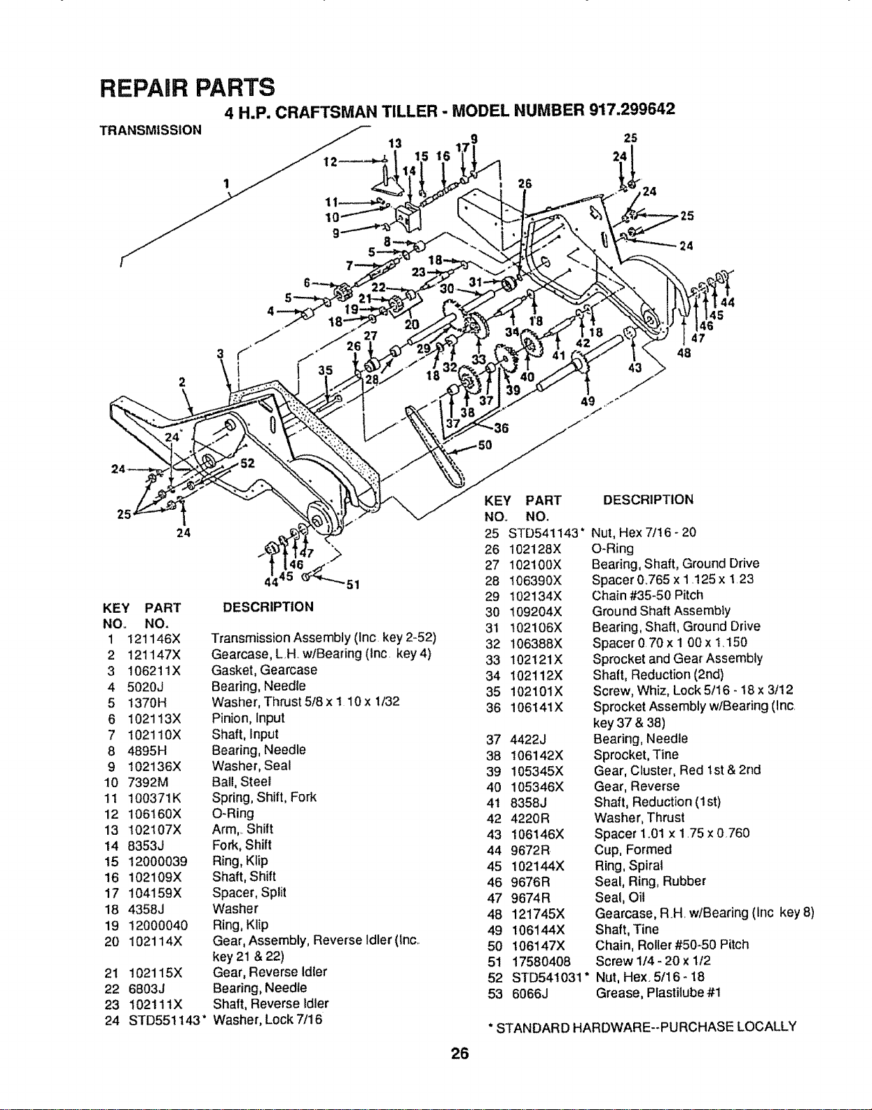
REPAIR PARTS
4 H.P, CRAFTSMAN TILLER - MODEL NUMBER 917.299642
TRANSMISSION 25
24
2G 24
24
43
44
45
46
47
48
>
24
KEY PART
NO. NO.
1 121146X
2 121147X
3 106211X
4 5020J
5 !370H
6 102113X
7 102110X
8 4895H
9 102136X
10 7392M
1t 100371K
12 106160X
13 102107X
14 8353J
15 12000039
16 102109X
17 104159X
18 4358J
19 12000040
20 102114X
21 102115X
22 6803J
23 102111X
24 STD551143"
7 >
44 "51
DESCRIPTION
Transmission Assembly (Inc key 2-52)
Gearcase, LH w/Bearing (Inc. key 4)
Gasket, Gearcase
Beadng, Needle
Washer, Thrust 5/8 x I 10 x 1/32
Pinion, Input
Shaft, Input
Bearing, Needle
Washer, Seal
Ball, Steel
Spring, Shift, Fork
O-Ring
Arm,..Shilt
Fork, Shift
Ring, Klip
Shaft, Shift
Spacer, Split
Washer
Ring, Klip
Gear, Assembly, Reverse Idler (lnc..
key 21 & 22)
Gear, Reverse Idler
Bearing, Needle
Shaft, Reverse Idler
Washer, Lock 7/16
26
KEY PART
NO_ NO.
25 STD541143"
26 102128X
27 102100X
28 !06390X
29 102134X
30 109204X
31 102106X
32 106388X
33 102121X
34 102112X
35 102101X
36 106141X
37 4422J
38 106142X
39 105345X
40 105346X
4t 8358J
42 4220R
43 106146X
44 9672R
45 102144X
46 9676R
47 9674R
48 121745X
49 106t44X
50 106147X
51 17580408
52 STD541031"
53 6066J
DESCRIPTION
Nut,Hex 7/t6 - 20
O-Ring
Bearing, Shaft, Ground Drive
Spacer 0.765 x I _125x 1 23
Chain #35-50 Pitch
Ground Shaft Assembly
Bearing, Shaft, Ground Drive
Spacer070x 1 00x 1_150
Sprocket and Gear Assembly
Shaft, Reduction (2nd)
Screw, Whiz, Lock 5/16 - 18 x 3/12
Sprocket Assembly w/Bearing (inc.
key 37 & 38)
Bearing, Needle
Sprocket, Tine
Gear, Cluster, Red 1st & 2nd
Gear, Reverse
Shaft, Reduction (I st)
Washer, Thrust
Spacer 1.01 x 175 x 0.760
Cup, Formed
Ring, Spiral
Seal, Ring, Rubber
Seal, Oil
Gearcase, RH w/Bearing (Inc key 8)
Shaft, Tine
Chain, Roller #50_50 Pitch
Screw 1/4- 20 x 1/2
Nut, Hex. 5/16- 18
Grease, Plastilube #1
* STANDARD HARDWARE--PURCHASE LOCALLY
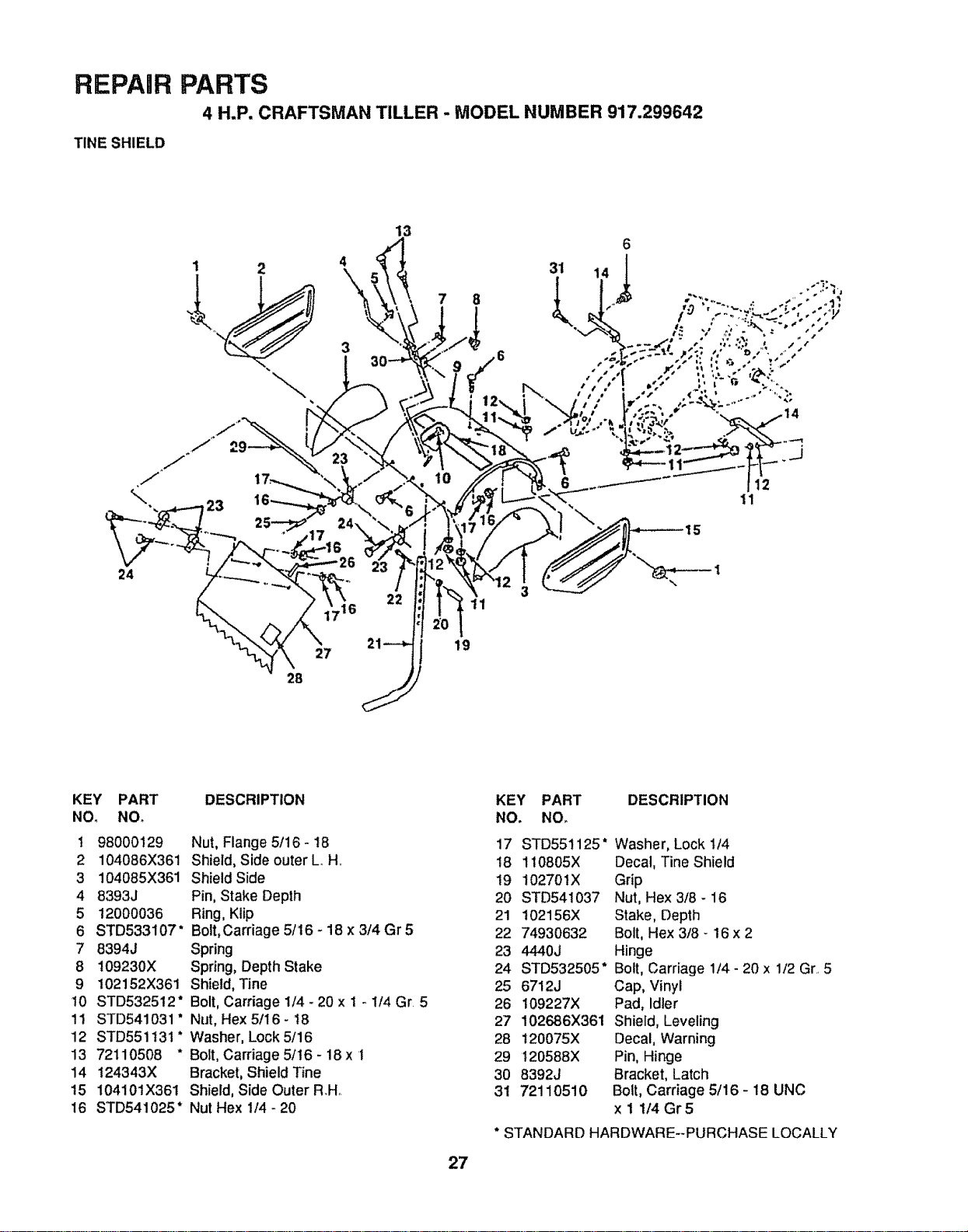
REPAIR PARTS
4 H.P. CRAFTSMAN TILLER - MODEL NUMBER 917.299642
TINE SHIELD
,J
%,
1 2
23
13
7
24
22
11
27
28
19
KEY PART
NO. NOr
1 98000129
2 104086X361
3 104085X361
4 8393J
5 12000036
6 STD533107"
7 8394J
8 109230X
9 t02152X361
!0 STD532512"
1! STD541031 *
12 STD551t31 *
13 72110508 *
14 124343X
15 10410tX361
16 STD541025"
DESCRIPTION
Nut, Flange 5/16 - 18
Shield,Side outer L H
Shield Side
Pin,Stake Depth
Ring,Klip
Bolt,Carriage 5/16 - 18 x 3/4 Gr 5
Spring
Spring, DepthStake
Shield,"Fine
Bolt, Carriage 1/4 - 20 x i _ 1/4 Gr 5
Nut, Hex 5/16- t8
Washer, Lock 5/16
Bolt,Carriage 5/t6 - 18 x 1
Bracket,ShieldTine
Shield, Side Outer RH
Nut Hex 1/4 - 20
27
KEY PART DESCRIPTION
NO. NO,
17
18
19
20
21
22
23
24
25
26
27
28
29
30
31
STD551125" Washer, Lock 1/4
1t0805X Decal, Tine Shield
102701X Grip
STD541037 Nut, Hex 3/8 - 16
102156X Stake, Depth
74930632 Bolt, Hex 3/8 - 16 x 2
4440J Hinge
STD532505" Bolt, Carriage 1/4- 20 x 1/2 Gr, 5
6712J Cap, Vinyl
109227X Pad, Idler
102686X361 Shield, Leveling
!20075X Decal, Warning
120588X Pin, Hinge
8392J Bracket, Latch
72110510 Bolt, Carriage 5/16 - 18 UNC
x 1 1/4 Gr 5
* STANDARD HARDWARE--PURCHASE LOCALLY
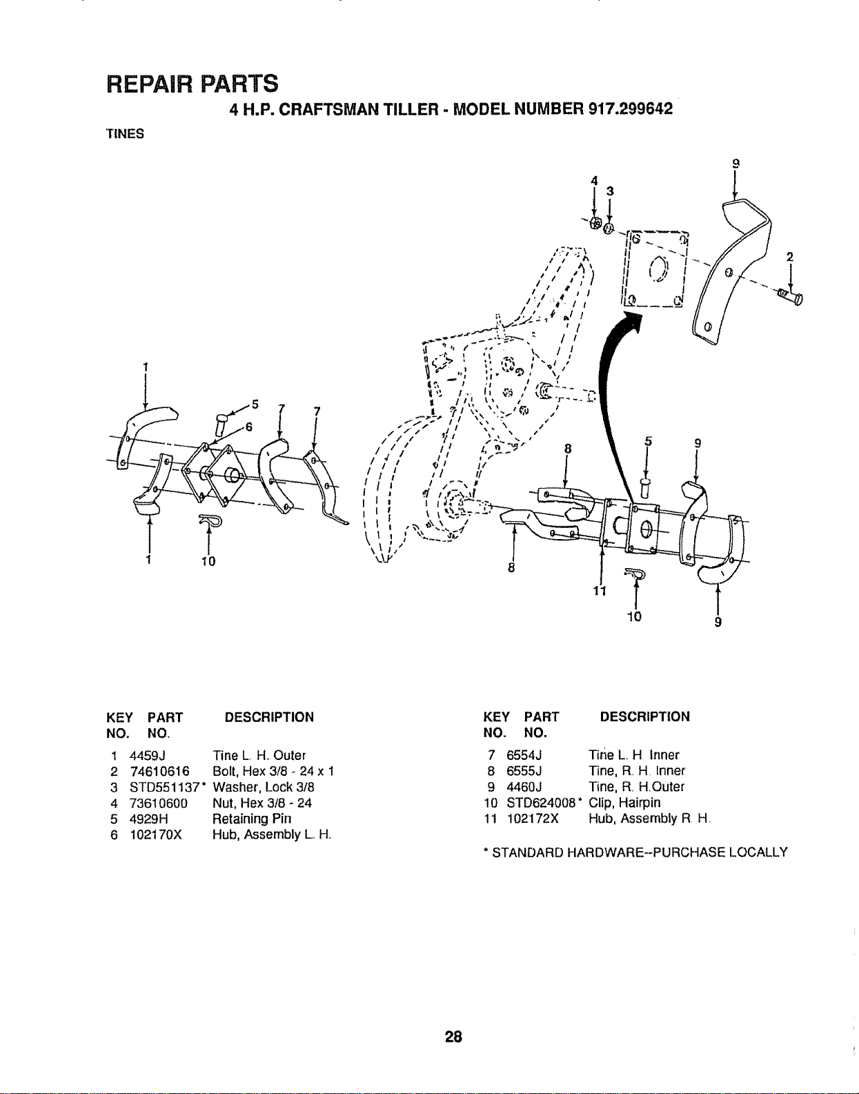
REPAIR PARTS
4 H.P. CRAFTSMAN TILLER - MODEL NUMBER 917.299642
TINES
1
t
T
10
KEY PART DESCRIPTION
NO. NO.
1 4459J Tine L H. Outer
2 74610616 Bolt, Hex 3/8 - 24 x 1
3 STD551137" Washer, Lock 3/8
4 73610600 Nut, Hex 3/8 - 24
5 4929H Retaining Pin
6 102170X Hub, Assembly L. H..
KEY PART DESCRIPTION
NOo NO.
7 6554J Tine L, H Inner
8 6555J Tine, R. H. Inner
9 4460J Tine, R H,Outer
10 STD624008" Clip, Hairpin
11 102172X Hub, Assembly R H.
* STANDARD HARDWARE--PURCHASE LOCALLY
28
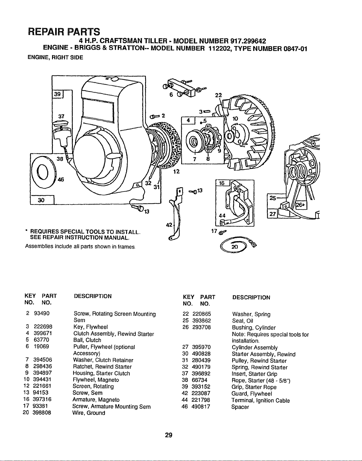
REPAIR PARTS
4 H.P, CRAFTSMAN TILLER - MODEL NUMBER 917.299642
ENGINE - BRIGGS & STRATTON-- MODEL NUMBER 112202, TYPE NUMBER 0847-01
ENGINE, RIGHT SIDE
22
10
* REQUIRES SPECIAL TOOLS TO INSTALL,
SEE REPAIR INSTRUCTION MANUAL°
Assemblies includeall parts shown in frames.
12
7 8
KEY PART DESCRIPTION KEY PART DESCRIPTION
NO. NO. NO. NO.
2 93490 Screw, Rotating Screen Mounting 22 220865 Washer, Spring
Sem 25 393862 Seal, Oil
3 222698 Key, Flywheel 26 293708 Bushing, Cylinder
4 399671 Clutch Assembly, Rewind Starter Note: Requires special tools lor
5 63770 Ball, Clutch installation,,
6 19069 Puller, Flywheel (optional 27 395970 Cylinder Assembly
Accessory) 30 490828 Starter Assembly, Rewind
7 394506 Washer, Clutch Retainer 31 280439 Pulley, Rewind Starter
8 298436 Ratchet, Rewind Starter 32 490179 Spring, Rewind Starter
9 394897 Housing, Starter Clutch 37 396892 Insert, Starter Grip
10 394431 Flywheel, Magneto 38 66734 Rope, Starter (48 +5/8")
t2 221661 Screen, Rotating 39 393152 Grip, Starter Rope
13 94153 Screw, Sere 42 223087 Guard, Flywheel
16 397316 Armature, Magneto 44 22!798 Terminal, ignitionCable
17 93381 Screw, Armature Mounting Sem 46 490817 Spacer
20 398808 Wire, Ground
29
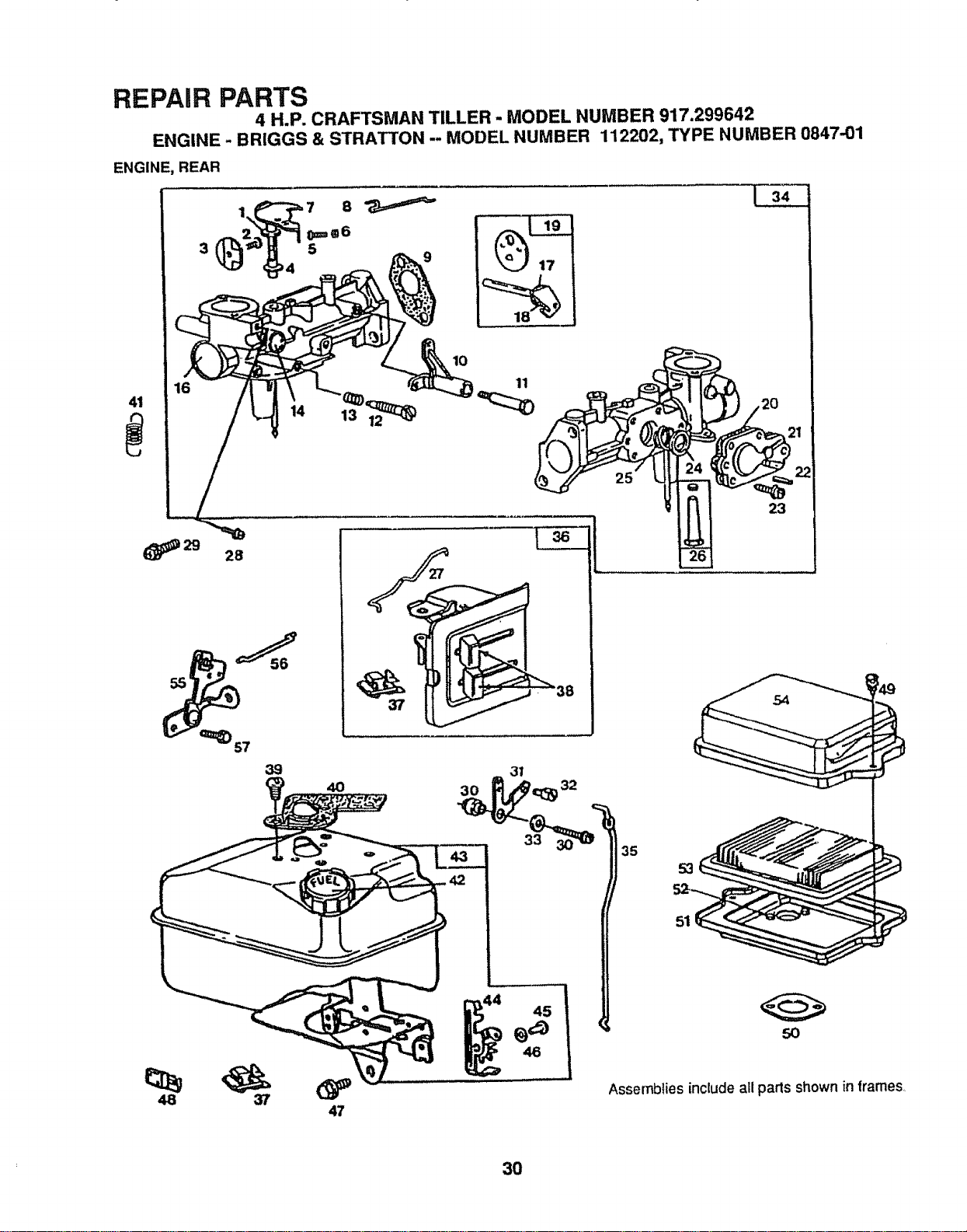
REPAIR PARTS
4 H.P. CRAFTSMAN TILLER - MODEL NUMBER 917.299642
ENGINE - BRIGGS & STRATTON -- MODEL NUMBER 112202, TYPE NUMBER 0847-01
ENGINE, REAR
3
16
41
(_29 28
14
10
11
39
4O
47
37
23
54
53
51
50
Assemblies include all pads shown in frames,
3O
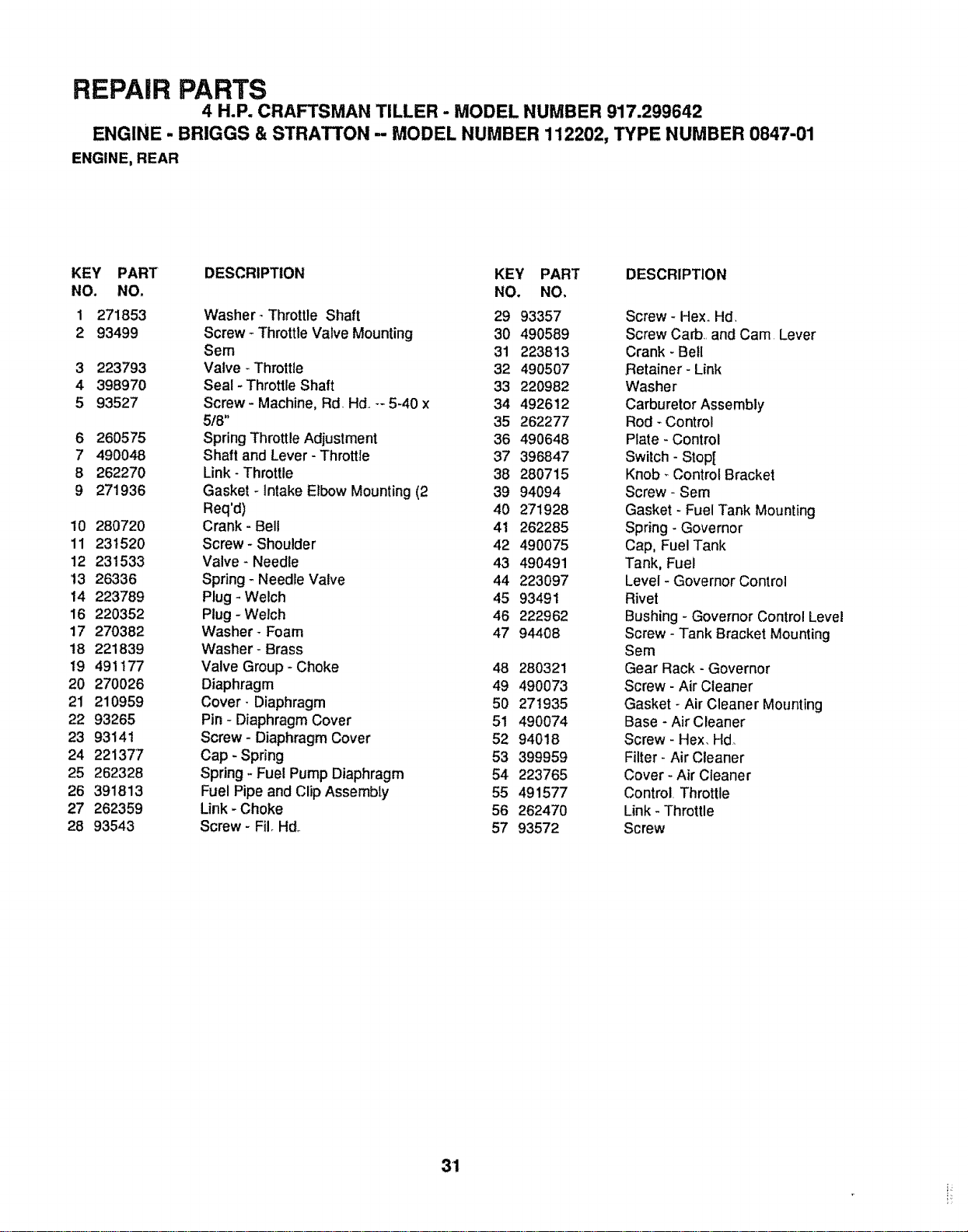
REPAIR PARTS
4 H.P. CRAFTSMAN TILLER - MODEL NUMBER 917.299642
ENGINE - BRIGGS & STRATTON - MODEL NUMBER 112202, TYPE NUMBER 0847-01
ENGINE, REAR
KEY PART DESCRIPTION KEY PART DESCRIPTION
NO. NO, NO. NO,
1 271853 Washer- Throttle Shaft 29 93357 Screw - Hex_Hd,
2 93499 Screw _ThrottleValve Mounting 30 490589 Screw Carb,,and Cam Lever
Sem 31 223813 Crank- Bell
3 223793 Valve _Throttle 32 490507 Retainer - Link
4 398970 Seal-Throttle Shaft 33 220982 Washer
5 93527 Screw- Machine, Rd. Hd..-- 5-40 x 34 492612 Carburetor Assembly
518" 35 262277 Rod - Control
6 260575 Spring Throttle Adjustment 36 490648 Plate- Control
7 490048 Shaft and Lever - Throttle 37 396847 Switch - Stop[
8 262270 Link- Throttle 38 280715 Knob- Control Bracket
9 271936 Gasket -Intake Elbow Mounting (2 39 94094 Screw- Sem
Req'd) 40 271928 Gasket - Fuel Tank Mounting
10 280720 Crank- Bell 41 262285 Spring- Governor
11 231520 Screw- Shoulder 42 490075 Cap, Fuel Tank
12 231533 Valve- Needle 43 490491 Tank, Fuel
!3 26336 Spring _Needle Valve 44 223097 Level - Governor Control
14 223789 Plug-Welch 45 93491 Rivet
16 220352 Plug -Welch 46 222962 Bushing - Governor Control Level
17 270382 Washer- Foam 47 94408 Screw - Tank Bracket Mounting
18 221839 Washer- Brass Sem
19 491t77 Valve Group - Choke 48 280321 Gear Rack - Governor
20 270026 Diaphragm 49 490073 Screw- Air Cleaner
21 210959 Cover- Diaphragm 50 271935 Gasket -Air Cleaner Mounting
22 93265 Pin - Diaphragm Cover 51 490074 Base - Air Cleaner
23 93141 Screw- Diaphragm Cover 52 94018 Screw - Hex, Hd_
24 221377 Cap - Spring 53 399959 Filter- Air Cleaner
25 262328 Spring - Fuel Pump Diaphragm 54 223765 Cover - Air Cleaner
26 391813 Fuel Pipe and Clip Assembly 55 491577 Control. Throttle
27 262359 Link - Choke 56 262470 Link - Throttle
28 93543 Screw- Fil_Hd,. 57 93572 Screw
31
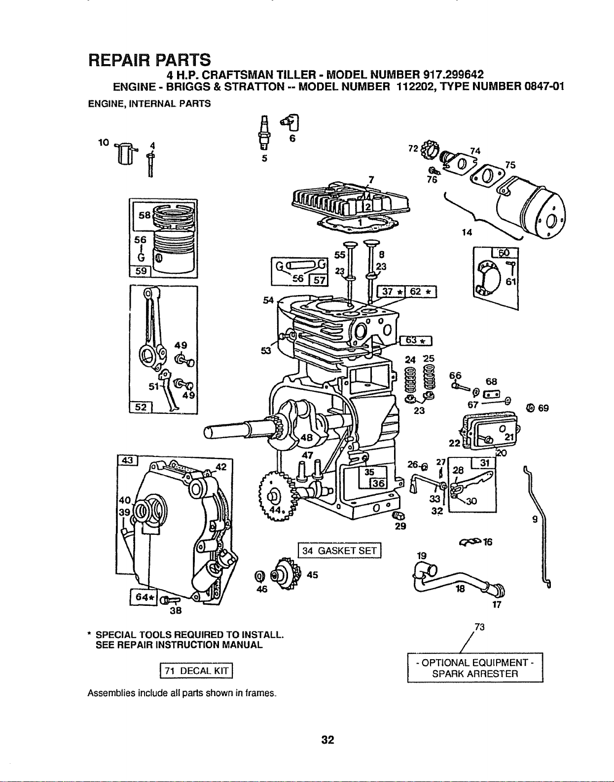
REPAIR PARTS
4 H.P. CRAFTSMAN TILLER - MODEL NUMBER 917.299642
ENGINE- BRIGGS & STRATTON -- MODEL NUMBER 112202, TYPE NUMBER 0847.01
ENGINE, INTERNAL PARTS
6
5
7
72,
76
14
74
75
49
54
134 GASKET SET]
@_4s
46
38
* SPECIAL TOOLS REQUIRED TO INSTALL,
SEE REPAIR INSTRUCTION MANUAL
t71 DECAL KIT 1
8
23
24 25
L
23
26.._ 27
32
29
19
17
69
73
/
f 1
- OPTIONAL EQUIPMENT-
SPARK ARRESTER
Assemblies includeall parts shown inframes,,
32
REPAIR PARTS
4 H.P. CRAFTSMAN TILLER - MODEL NUMBER 917.299642
ENGINE - BRIGGS & STRATTON -- MODEL NUMBER 112202, TYPE NUMBER 0847-01
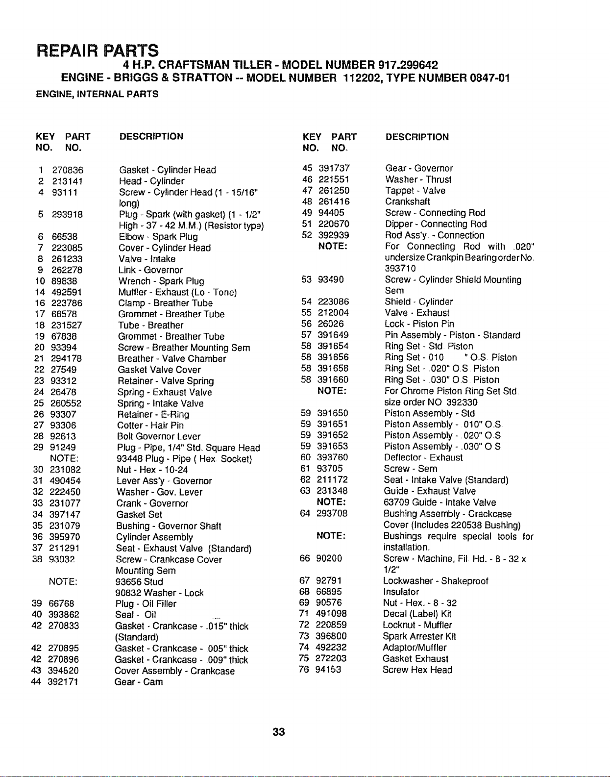
ENGINE, INTERNAL PARTS
KEY PART DESCRIPTION KEY PART DESCRIPTION
NO. NO. NO, NO.
1 270836
2 213141
4 93111
5 293918
6 66538
7 223085
8 261233
9 262278
10 89838
14 492591
16 223786
17 66578
18 231527
19 67838
20 93394
21 294178
22 27549
23 93312
24 26478
25 260552
26 93307
27 93306
28 92613
29 91249
NOTE:
30 231082
31 490454
32 222450
33 231077
34 397147
35 231079
36 395970
37 211291
38 93032
NOTE:
39 66768
40 393862
42 270833
42 270895
42 270896
43 394820
44 392171
Gasket - Cylinder Head 45 391737
Head- Cylinder 46 221551
Screw- Cylinder Head (1 - 15/16" 47 261250
long) 48 261416
Plug _Spark (with gasket) (1 - 1/2" 49 94405
High - 37 - 42 M.M.)(Resistor type) 51 220670
Elbow - Spark Plug 52 392939
Cover - Cylinder Head NOTE:
Valve - Intake
Link - Governor
Wrench - Spark Plug 53 93490
Muffler - Exhaust (Lo - Tone)
Clamp - Breather Tube 54 223086
Grommet - Breather Tube 55 212004
Tube- Breather 56 26026
Grommet - Breather Tube 57 391649
Screw- Breather Mounting Sem 58 391654
Breather- Valve Chamber 58 391656
Gasket Valve Cover 58 391658
Retainer- Valve Spring 58 391660
Spring - Exhaust Valve NOTE:
Spring _ Intake Valve
Retainer- E-Ring 59 391650
Cotter- Hair Pin 59 391651
Bolt Governor Lever 59 391652
Plug - Pipe, 1/4" Std. Square Head 59 391653
93448 Plug - Pipe ( Hex Socket) 60 393760
Nut - Hex - 10-24 61 93705
Lever Ass'y _Governor 62 211172
Washer- GovoLever 63 231348
Crank - Governor NOTE:
Gasket Set 64 293708
Bushing - Governor Shaft
Cylinder Assembly NOTE"
Seat - Exhaust Valve (Standard)
Screw- Crankcase Cover 66 90200
Mounting Sem
93656 Stud 67 92791
90832 Washer- Lock 68 66895
Plug- Oil Filler 69 90576
Seal- Oil ....... 71 491098
Gasket - Crankcase -..015" thick 72 220859
(Standard) 73 396800
Gasket _Crankcase - O05" thick 74 492232
Gasket - Crankcase - 009" thick 75 272203
Cover Assembty- Crankcase 76 94153
Gear- Cam
Gear- Governor
Washer- Thrust
Tappet - Valve
Crankshaft
Screw - Connecting Rod
Dipper* Connecting Rod
Rod Ass'y, - Connection
For Connecting Rod with .020"
unde rsize Crankpin Bearing order No,
393710
Screw - Cylinder Shield Mounting
Sere
Shield- Cylinder
Valve - Exhaust
Lock - Piston Pin
Pin Assembly - Piston - Standard
Ring Set - Std Piston
Ring Set - 010 "OS. Piston
Ring Set - .020" O.S. Piston
Ring Set - .030" OS Piston
For Chrome Piston Ring Set Std
size order NO 392330
Piston Assembly - Std
Piston Assembly - 010" O.S
Piston Assembly -. 020" O,S.
Piston Assembly- _,030"O S.
Deflector- Exhaust
Screw - Sem
Seat - Intake Valve (Standard)
Guide - Exhaust Valve
63709 Guide - Intake Valve
Bushing Assembly - Crackcase
Cover (includes 220538 Bushing)
Bushings require special tools for
instaUation.
Screw - Machine, Fil. Hd.,- 8 - 32 x
I/2"
Lockwasher - Shakeproof
Insulator
Nut - Hex_- 8 - 32
Decal (Label) Kit
Locknut - Muffler
Spark Arrester Kit
Adaptor/Muffler
Gasket Exhaust
Screw Hex Head
33

lll£Vl@l 1II@?!i8
34

IIIi£VIGII 111)1118
35
OWNERS
MANUAL
MODEL NO.
917.299642
HOW TO ORDER
REPAIR PARTS
£RRFTXMaN
4.0 POWER
14 INCH TI WIDTH
COUNTER ROTATING TINES
R AR TINE TILLER
Each Tiller has its own model number,, Each Engine has itsown model
number,_
The Model Number for your Tillerwillbe found on a plate attached to the
top of the Transmission.
The model numberfor the Engine will be found on the BlowerHousing of
the Engine adjacent to theSpark Plug,,
All parts listed herein may be orderedfrom any Sears, Roebuck and Co.
Service Centers and most Retail Stores
WHEN ORDERING REPAIR PARTS, ALWAYS GIVE THE FOLLOWING
INFORMATION:
o PRODUCT - "REAR TINE TILLER"
o MODEL NUMBER - 917.299641
o ENGINE MODEL NUMBER -112202 - TYPE NUMBER -0847-01
o PART NUMBER
• PART DESCRIPTION
Your Sears merchandise has added value when you consider Searshas
service unitsnationwide staffed with Sears trained technicians°.°profes-
sional technicians specifically trained to insure that we meet our pledge
to you, we service what we sell.
Sears, Roebuck and Co., Chicago, IL 60684 U.S.A.
124340X2E 4690 PRINTED IN U,S,A,