Operator's Manual
II:RRFI"SMRN I
8 HORSEPOWER
REAR TINE TILLER
Model No: 987.293330
CAUTION:
Before using this tiller, read
this manual and follow all its
Safety Rules and Operating
Instructions,
• Safety Rules
• Assembly
• Operation
• Maintenance
• Parts
Sears, Roebuck and Co., Hoffman Estates, IL 60179 U.S.A.
Visit the Craftsmanweb page:www.sears.com/craftsman
SAFETY RULES
_ CAUTION: ALWAYS DISCONNECT SPARK PLUG WIRE AND PLACE WIRE WHERE IT
CANNOT CONTACT SPARK PLUG TO PREVENT ACCIDENTAL STARTING WHEN SET-
TING UP, TRANSPORTING, ADJUSTING OR MAKING REPAIRS.
u
TRAINING
1. Carefully readthis Owner's Manual
andanyother literature you may receive
before operatingthis equipment. Be
thoroughly familiar with the controls and
the proper useof the tiller and its.engine.
Knowhow to stop the unit and disengage
the controls quickly.
2. Neverallowchildrento operatethe
tiller. Neverallowadults to operatethe
tiller without proper instruction.
3. Keepthe areaof operationclearof all
persons, particularly children and pets.
Keepbystanders at least25 feetfrom
areaof operation.
4. Keepin mind that the operator or user
is responsiblefor accidents or hazards
occurring to other people,their property,
and themselves.
5. Familiarizeyourself with allof the
safetyandoperatingdecals on this"
equipifiedt andon any of its attachments
or accessories.
6. Donot run enginein an enclosedarea.
Engineexhaustcontainscarbon monox-
ide gas, a deadlypoison that is odorless,
colorless, and tasteless. Do not operate
this equipmentnearbuildings, windows,
or airconditioners.
7. Do not allow handsor anyother part
of the body or clothing nearthe rotating
tines or nearany other moving part. The
tines beginto rotate backward oncethe
engine starts, and eitherthe Forward
Clutchor the
ReverseClutch
Leveris engaged
(theWheelGear
Levermustalways
be moved to EN-
GAGEbeforethe
engine is started).
8. Beforeinspectingor servicing any
partof the equipment, shut off the
engine,wait for all moving parts to come
to a complete stop, disconnect the spark
plug wire from the spark plug, and move
the wire awayfrom the spark plug.
g. Donot operatethis equipment if you
are under the influence of alcohol, medi-
cation,or whentired or ill.
PREPARATION
1. Thoroughlyinspect the areawhere
the tiller is to be usedand remove all for-
eign objects.
2. Besure all control levers are released
andthe Wheel GearLever isin ENGAGE
beforestarting the engine.
3. Donot operatethetiller without wear-
ing adequateouter garments. Avoid
loose garmentsor jewelry that could get
caught in moving parts of tiller or engine.
4. Donot operatethetiller whenbarefoot
orwearingsandals,sneakers,or light
footwear. Wearprotectivefootwearthat
will improve footing on slippery surfaces.
5. Do nottill nearundergroundelectricca-
bles,telephonelines,pipesor hoses. If in
doubt, contactyourtelephoneor utility
company.
6. Warning:Handlefuel withcare;it is
highlyflammableand itsvaporsareexplo-
sive. Takethefollowing precautions:
a. Store fuel in containersspecifically
designedfor this purpose.
b. Thegas capshall neverbe re-
moved or fuel addedwhile the en-
gine is running. Allow the engine
to coo[ for several minutes before
adding fuel.
c. Keepmatches,cigarettes,cigars,
pipes, open flames, and sparks
awayfrom thefuel tank andfuel
container.
d. Fillfuel tank outdoors with extreme
care. Neverfill fuel tank indoors.
Use afunnel or spout to prevent
spillage.
e. Replaceallfuel tank andcontainer
capssecurely.
f. If fuel is spilled, do not attempt to
start the engine,but move the
machineawayfrom the areaof
spillage andavoid creating any
source of ignition until fuel vapors
havedissipated.
7. Nevermakeadjustmentswhenengine
is running (unless recommendedby
manufacturer).
OPERATION
1. Donot put handsor feet nearor un-
der rotating parts.
2. Exerciseextreme cautionwhen on or
crossing gravel drives,walks, or roads.
Stay alertfor hidden hazardsor traffic.
Do not carry passengers.
3. After striking aforeign object, stop the
engine,disconnect the spark plug wire
and prevent it from touching the spark
plug, carefully inspect thetiller for any
damage,and repairthe damagebefore
restarting and operatLngthe tiller.
4. Exercisecautionto avoidslipping or
falling.
5. Iftheunit shouldstartto vibrateabnor-
mally,stop theengine. Disconnectthe
spark plug wireand preventit from touch-
ingthe sparkplug, andcheckimmediately
for the cause.Vibration is generallya
warning of trouble.
6. Stop the engine,disconnect the spark
plug wire and prevent it from touching
the spark plug wheneveryou leavethe
operating position, before unclogging the
tines, or when making any repairs, ad-
justments or inspections.
7. Takeall possibleprecautionswhen
leavingthe machineunattended.Stopthe
engine.Disconnect spark plug wire and
move itawayfrom the spark plug. Move
WheelGearLeverto ENGAGE.
8. Beforecleaning, repairing, or inspect-
ing,stop the engine,and makecertain all
moving parts havestopped. Disconnect
the spark plug wire and preventit from
touching the spark plug to preventacci-
dentalstarting.
9. Always keepthe tiller tine hood flap
down.
LOOK FOR THIS SYMBOL TO POINT OUT IMPORTANT SAFETY PRECAUTIONS.
IT MEANS-ATTENTIONH[ BECOME ALERTIH YOUR SAFETY IS INVOLVED.
© Sears, Roebuck and Co.
2
SAFETY RULES
10. Neverusethe tiller unlessproper
guards,plates,or othersafetyprotective
devicesareinplace.
11. Do not run engine in an enclosed
area.Engineexhaustcontains carbon
monoxide gas, a deadlypoisonthat is
odorless, colorless, and tasteless.
1;'. Keepchildrenand petsaway.
13. Neveroperatethe tiller under engine
power if the WheelGearLeveris in
DISENGAGE(FREEWHEEL).In this posi-
tion, the wheelswill not hold the tiller
back and the revolving tines could propel
the tiller rapidly backward, possibly caus-
ing loss of control. Always move the
WheelGearLeverto ENGAGEbefore
•starting the engineorengagingthe
tines/wheels with the Forward Clutch or
the ReverseClutch.
14. Beawarethattheti_lermay unex-
pectedlybounce upwardor jump back-
ward if thetines should strike extremely
hard packedsoil, frozen ground, or
buried obstacleslike large stones, roots,
Qrstumps. If in doubt about the tilling
conditions, always usethefollowing op-
erating precautionsto assist you in main-
taining control of the tiller:
a. Walkbehindandto one side ofthe
.,, tilier,,using one hand on the han-
dlebars. Relaxyour arm, but usea
secure hand grip.
b. Useslower engine speeds.
c. Clearthe tilling area of all large
stones, roots and other debris.
d. Avoid using downward pressure on
handlebars. If needbe, useslight
upward pressure to keepthe tines
..... from digging too deeply.
• e. In an emergency,stoptines and
wheels byreleasingwhichever
ClutchLeveris engaged.Do not
attemptto restrainthetiller.
15. Do not overloadthe tiller's capacity
by attemptingto till too deeplyattoo fast
a rate.
16. Neveroperatethetillerat high trans-
portspeeds on hard or slippery surfaces,
Lookbehindand usecarewhenbacking
up.
17. Donot operatethetilleron a slope
thatistoo steepfor safety.Whenon
slopes,slowdownand makesureyou
havegoodfooting. Neverpermitthetiller
to freewheeldownslopes.
18. Neverallowbystandersnearthe
unit.
19. Only useattachmentsandacces-
soriesthat areapprovedby thetiller
manufacturer.
20. Usetiller attachmentsand acces-
sories when recommended.
21. Neveroperatethetiller without good
visibilityor light.
22. Neveroperatethetiller ifyou aretired,
or underthe influenceof alcohol,drugsor
medication.
23. Operatorsshallnottamperwiththe
engine-governorsettingsonthemachine;
thegovernorcontrolsthe maximumsafe
operatingspeedto protecttheengineand
all moving partsfrom damagecausedby
overspeed.Authorizedserviceshallbe
sought ifa problemexists.
24. Donottouch enginepartswhich may
behotfrom operation.Letpartscooldown
sufficiently.
25. Pleaseremember:Youcanalways
stopthetines andwheelsbyreleasingthe
ForwardClutchLeveror theReverseClutch
Lever(whicheverleveryou haveengaged)
or bymovingtheThrottleControlLeverto
STOP.
26. Toloador unloadthetiller, seethein-
structionsinthisManual.
27. Useextremecautionwhenreversing
or pullingthemachinetowardsyou.
28. Startthe enginecarefullyaccordingto
instructionsandwith feetwellawayfrom
thetines.
29. Neverpick upor carrya machinewhile
theengineisrunning.
MAINTENANCE/STORAGE
1. Keepthe tiller,attachments andacces-
sories in safe workingcondition.
2. Checkall nuts, bolts, andscrews at
frequent intervalsfor propertightness to
besure the equipment is in safeworking
condition.
3. Neverstorethetillerwith fuel inthe fuel
tank insidea buildingwhereignition
sourcesare present(suchashot waterand
spaceheaters,furnaces,clothesdryers,
stoves,electricmotors, etc.). Allowengine
to coolbeforestoring in anyenclosure.
4. Toreducethechancesof afire hazard,
keeptheenginefreeof grass,leaves,or
excessivegrease.
5. Storegasolineina cool,well-ventilat-
edarea,safelyawayfrom anyspark-or
flame-producing equipment.Storegaso-
lineinanapprovedcontainer,safelyaway
from the reachofchildren.
6. Referto the ServiceandAdjustments
Section ofthis Manualif thetiller is to be
stored for an extendedperiod.
7. Neverperform maintenancewhile the
engine is running or thespark plugwire is
connected,exceptwhen specificallyin-
structed to do so.
8. Ifthe fuel tank hasto be drained,do
this outdoors.
TOAVOIDINJURY:
• READOWNER'SMANUAL.
• KNOW LOCATION AND
FUNCTION OF ALL CON-
TROLS.
• KEEPALL SAFETYDEVICES
AND SHIELDS IN PLACE
ANDWORKING,
• NEVERALLOW CHILDREN
ORUNINSTRUCTEDADULTS
TOOPERATETILLER.
• SHUT OFF ENGINE AND
DISCONNECTSPARKPLUG
WIRE BEFORE UNCLOG-
GING TINES OR MAKING
REPAIRS.
• KEEPBYSTANDERSAWAY
FROMMACHINE,
• KEEPAWAYFROM ROTAT-
INGPARTS.
• USE EXTREME CAUTION
WHEN REVERSING OR
PULLINGTHE MACHINETO-
WARDSYOU.
WARNING:
The engine exhaust from this
product contains chemica!s
knownto the StateofCaliformai
to cause cancer, birth defects,i
orotherreproductiveharm.
CONGRATULATIONS on your purchase of a Sears
Craftsman tiller. It has been designed, engineered and
manufactured to give you the best possible dependability
and performance.
Should you experience any problems you cannot easily
remedy,please contact your nearest Sears Service Cen-
ter/Department. We have competent, well-trained tech-
nicians and the proper tools to service or repair this
machine.
Please read and retain this manual. The instructions will
help you assemble and maintain your machine properly.
Always observe the "SAFETY RULES."
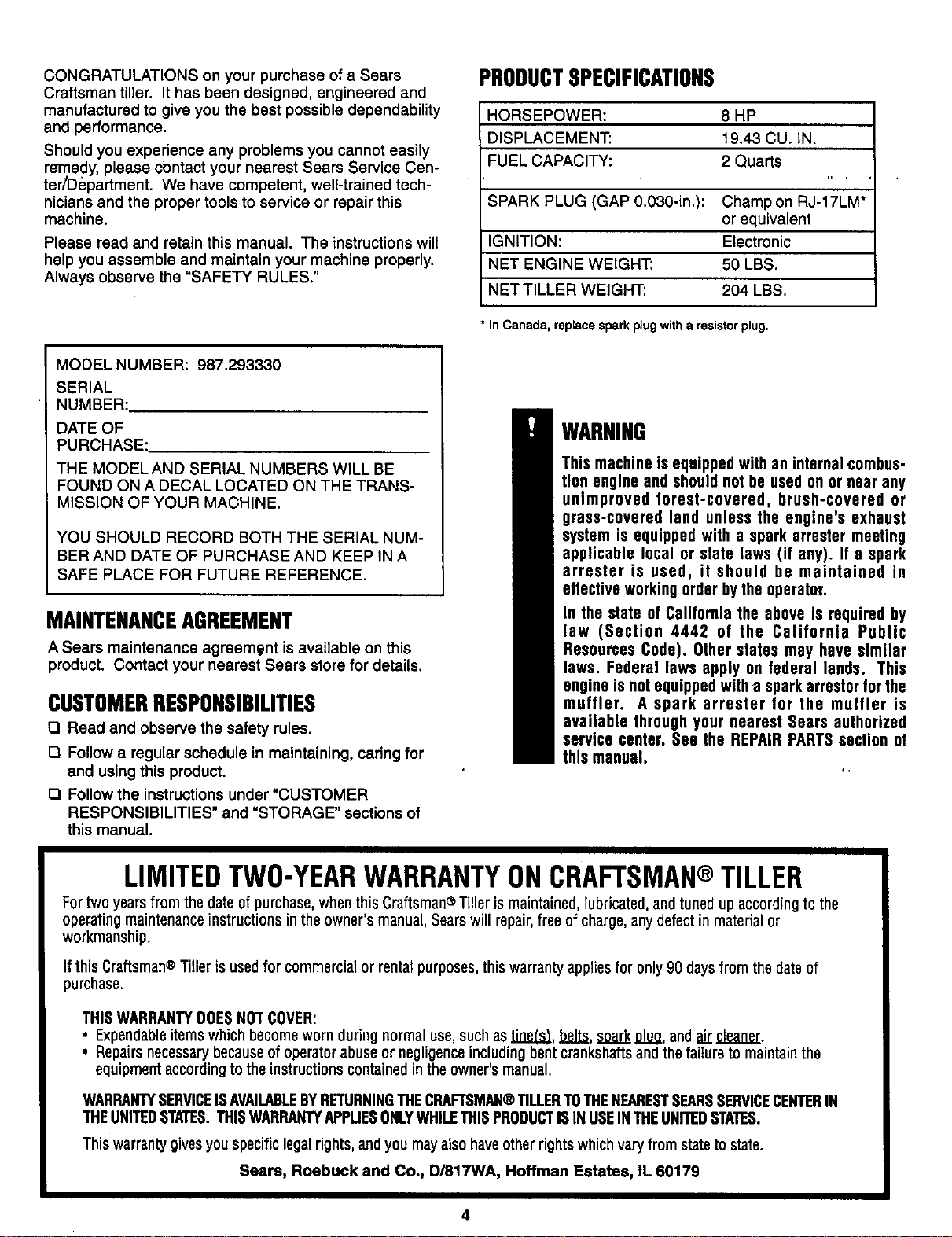
MODEL NUMBER: 987.293330
SERIAL
NUMBER:
DATE OF
PURCHASE:
THE MODELAND SERIAL NUMBERS WILL BE
FOUND ON A DECAL LOCATED ON THE TRANS-
MISSION OF YOUR MACHINE.
YOU SHOULD RECORD BOTH THE SERIAL NUM-
BER AND DATE OF PURCHASE AND KEEP IN A
SAFE PLACE FOR FUTURE REFERENCE.
MAINTENANCEAGREEMENT
A Sears maintenance agreement is available on this
product. Contact your nearest Sears store for details.
CUSTOMERRESPONSIBILITIES
O Read and observe the safety rules.
O Follow a regular schedule in maintaining, caring for
and using this product.
[] Follow the instructions under "CUSTOMER
RESPONSIBILITIES" and "STORAGE" sections of
this manual.
PRODUCTSPECIFICATIONS
HORSEPOWER: 8 HP
DISPLACEMENT: 19.43 CU. iN.
FUEL CAPACITY: 2 Quarts
SPARK PLUG (GAP 0.030-in.): Champion RJ-17LM*
or equivalent
IGNITION: Electronic
NET ENGINE WEIGHT: 50 LBS.
NET TILLER WEIGHT: 204 LBS.
• InCanada, replacespark plugwitha resistorplug.
WARNING
This machine is equipped with an internal combus-
tion engine and shouldnot be used on or near any
unimproved forest-covered, brush-covered or
grass-covered land unless the engine's exhaust
system is equipped with a spark arresfer meeting
applicable local or state laws (if any). If a spark
arrester is used, it should be maintained in
effective workingorder bythe operator.
In the state of California the above is required by
law (Section 4442 of the California Public
Resources Code). Other states may have similar
laws. Federal laws apply on federal lands. This
engine is not equippedwith a spark arrestor for the
muffler. Asparkarrester for the muffler is
available through your nearest Sears authorized
service center. See the REPAIR PARTSsection of
this manual.
*,
LIMITEDTWO-YEARWARRANTYONCRAFTSMAN®TILLER
Fortwo years from the dateof purchase,when this Craftsman®Tiller ismaintained,lubricated, and tuned up according to the
operating maintenanceinstructions in the owner's manual, Searswill repair,free of charge, anydefect in material or
workmanship.
Ifthis Craftsman®Tilleris usedfor commercialor rental purposes,thiswarrantyappliesfor only90 daysfrom the dateof
purchase.
THISWARRANTYDOESNOTCOVER:
• Expendableitems whichbecomewornduringnormaluse,suchastJQ.P,.(._,belts,soarkglue, andair cleaner.
• Repairsnecessarybecauseofoperatorabuseor negligenceincludingbentcrankshaftsandthefailureto maintain the
equipmentaccordingtotheinstructionscontainedintheowner'smanual.
WARRANTYSERVICEISAVAILABLEBYRETURNINGTHECRAFTSMAN@TILLERTOTHENEARESTSEARSSERVICECENTERIN
THEUNITEDSTATES.THISWARRANTYAPPLIESONLYWHILETHISPRODUCTISIN USEINTHEUNITEDSTATES.
Thiswarrantygivesyou specificlegalrights,andyou mayalso haveotherrightswhichvary from stateto state.
Sears, Roebuck and Co., D/817WA, Hoffman Estates, IL 60179
4
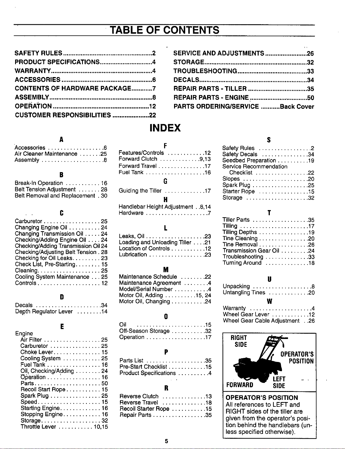
TABLE OF CONTENTS
SAFETY RULES ................................................... 2
PRODUCT SPECIFICATIONS .............................. 4
WARRANTY .......................................................... 4
ACCESSORIES .................................................... 6
CONTENTS OF HARDWARE PACKAGE ............ 7
ASSEMBLY ........................................................... 8
OPEI_ATION ....................................................... 12
CUSTOMER RESPONSIBILITIES ..................... 22
ii
SERVICE AND ADJUSTMENTS ........................ 26
STORAGE ........................................................... 32
TROUBLESHOOTING ........................................ 33
DECALS .............................................................. 34
REPAIR PARTS - TILLER .................................. 35
REPAIR PARTS - ENGINE: .................... ............ 50
PARTS ORDERING/SERVICE ........... Back Cover
A
Accessories .................. 6
Air Cleaner Maintenance ....... 25
Assembly .................... 8
B
Break-In Operation ........... 16
Belt Tension Adjustment ....... 28
Belt Removal and Replacement , 30
C
Carburetor .................. 25
Changing Engine Oil .......... 24
Changing Transmission Oil ..... 24
Checking/Adding Engine Oil .... 24
Checking/Adding Transmission Oil 24
Checking/Adjusting Belt Tension. 28
Checking for Oil Leaks ......... 23
Check List, Pre-Starting ........ 15
Cleaning .................... 25
Cooling System Maintenance... 25
Controls .................... 12
D
Decals ..................... 34
Depth Regulator Lever ........ 14
E
Engine
Air Filter .................. 25
Carburetor ................ 25
Choke Lever ............... 15
Cooling System ............ 25
Fuel Tank ................. 16
Oil, Checking/Adding ........ 24
O_5_rat'ion.... _............ 16
Parts ..................... 50
Recoil Start Rope ........... 15
Spark Plug ................ 25
Speed .................... 15
Starting Engine ............. 16
Stopping Engine ............ 16
Storage ................... 32
Throttle Lever ........... 10,15
INDEX
F
Features/Controls ............ 12
Forward Clutch ............. 9,13
Forward Travel ............... 17
Fuel Tank ................... 16
G
Guiding the Tiller ............. 17
il
Handlebar Height Adjustment . .8,14
Hardware .................... 7
Leaks, Oil ................... 23
Loading and Unloading Tiller .... 21
Location of Controls ........... 12
Lubrication .................. 23
M
Maintenance Schedule ........ 22
Maintenance Agreement ........ 4
Model/Serial Number ........... 4
Motor Oil, Adding .......... 15, 24
Motor Oil, Changing ........... 24
0
Oil ...................... 15
Off-Season Storage ........... 32
Operation ................... 17
P
Parts List ................... 35
Pre-Start Checklist ............ 15
Product Specifications .......... 4
R
Reverse Clutch .............. 13
Reverse Travel .............. 18
Recoil Starter Rope ........... 15
Repair Parts ................. 35
5
S
Safety Rules ................. 2
Safety Decals ............... 34
Seedbed Preparation .......... 19
Service Recommendation
Checklist ................. 22
Slopes ..................... 20
Spark Plug .................. 25
Starter Rope ................ 15
Storage .................... 32
T
Tiller Parts .................. 35
Tilling ...................... 17
Tilling Depths ................ 19
Tine Cleaning ................ 20
Tine Removal ................ 26
Transmission Gear Oil ......... 24
Troubleshooting .............. 33
Turning Around .............. 18
II
Unpacking ................... 8
Untangling Tines ............. 20
W
Warranty .................... 4
Wheel Gear Lever ............ 12
Wheel Gear Cable Adjustment . .26
RIGHT
SIDE
OPERATOR'S
POSITION
LEFT
FORWARD SIDE
OPERATOR'S POSITION
All references to LEFT and
RIGHT sides of the tiller are
given from the operator's posi-
tion behind the handlebars (un-
less specified otherwise).
ACCESSORIES
These accessories were available when the tiller was purchased. They are available at most Sears retail
outlets, catalog and service centers. Most Sears stores can order repair parts for you when you provide the
model number of your tiller.
ACCESSORIES
Spark Plug GasCan
"'Figure 1-1
Motor Oil
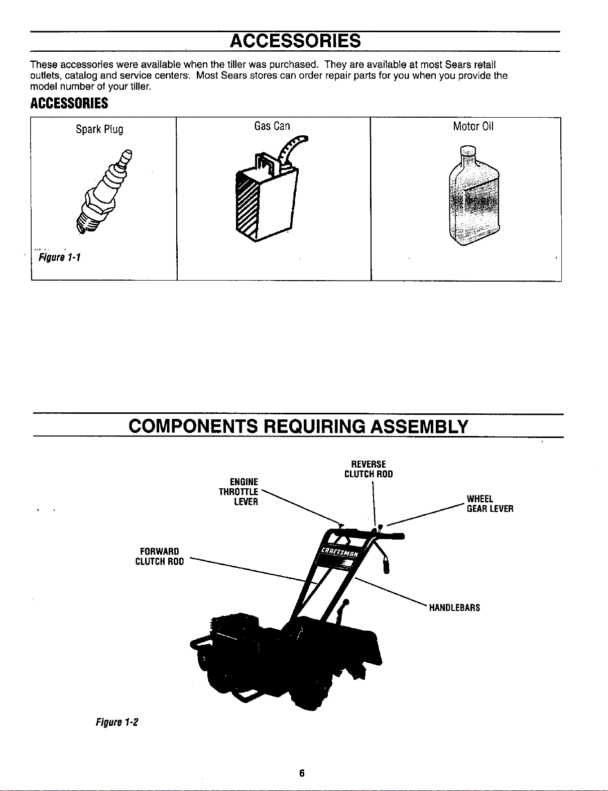
COMPONENTS REQUIRING ASSEMBLY
ENGINE
LEVER
REVERSE
CLUTCHROD
WHEEL
FORWARD
CLUTCHROD
HANDLEBARS
Figure1-2
6
10
©©
©©
Figure1.3
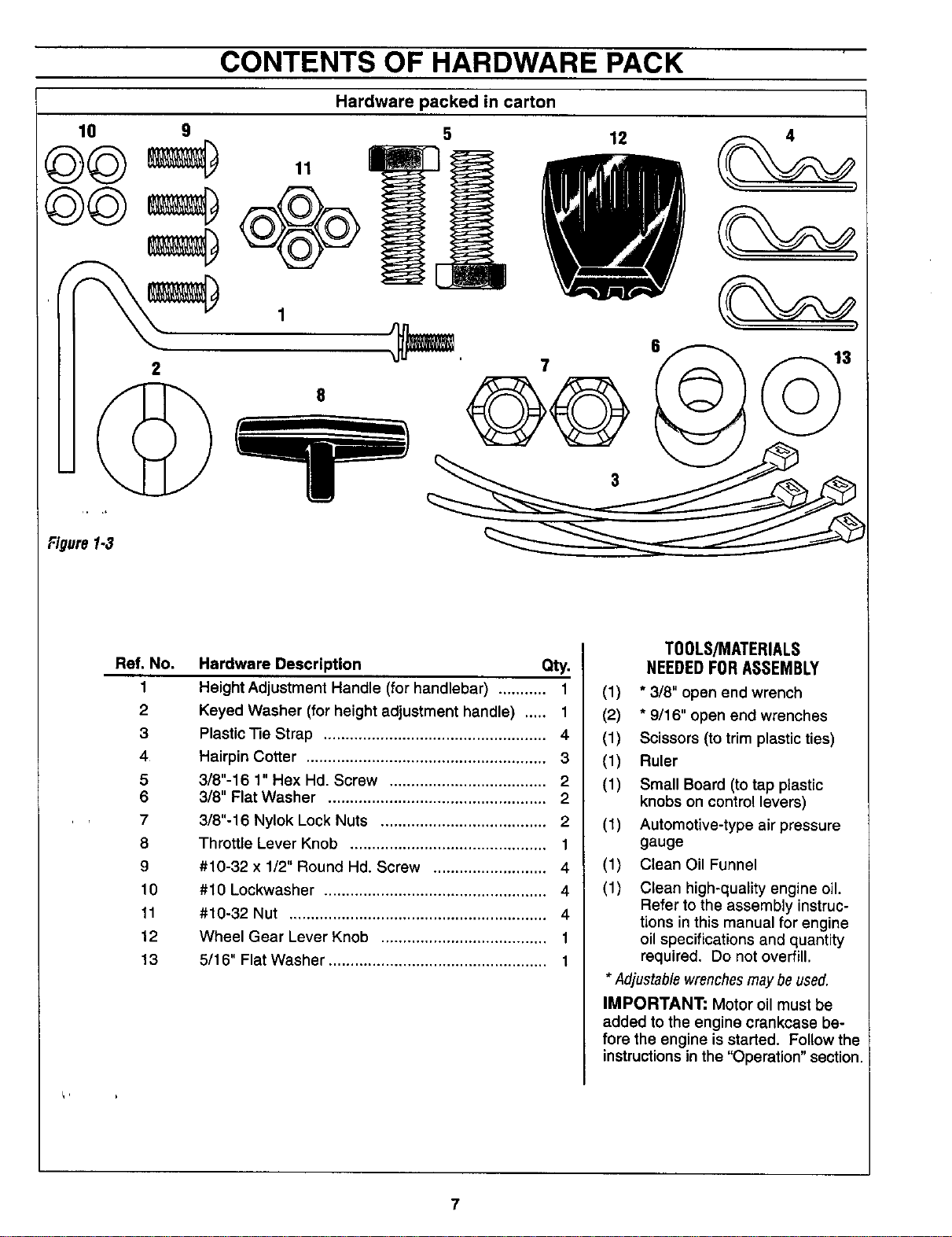
CONTENTS OF HARDWARE PACK
Hardware packed in carton
2
11,
Ref. No,
1
2
3
4
5
6
7
8
9
10
11
12
13
Hardware Description Qty.
Height Adjustment Handle (for handlebar) ........... 1
Keyed Washer (for height adjustment handle) ..... 1
Plastic Tie Strap ................................................... 4
Hairpin Cotter ....................................................... 3
3/8"-16 1" Hex Hd. Screw .................................... 2
3/8" Flat Washer .................................................. 2
3/8"-16 Nylok Lock Nuts ...................................... 2
Throttle Lever Knob ............................................. 1
#10-32 x 1/2" Round Hd. Screw .......................... 4
#10 Lockwasher ................................................... 4
#10-32 Nut ........................................................... 4
Wheel Gear Lever Knob ...................................... 1
5/16" Flat Washer .................................................. 1
T00LS/MATERIALS
NEEDEDFOR ASSEMBLY
(1) * 3/8" open end wrench
(2) * 9/16" open end wrenches
(1) Scissors (to trim plasticties)
(1) Ruler
(1) Small Board (to tap plastic
knobs on control levers)
(1) Automotive-type air pressure
gauge
(1) Clean Oil Funnel
(1) Clean high-quality engine oil.
Refer to the assembly instruc-
tions in this manual for engine
oil specifications and quantity
required. Do not overfill.
•Adjustable wrenchesmay be used.
IMPORTANT: Motor oil must be
added to the engine crankcase be-
fore the engine is started. Follow the
instructionsin the "Operation" section.
7
ASSEMBLY
Read these instructions completely
before you attempt to assemble or
operate your new equipment. Your
tiller has been assembled at the fac-
tory with the exception of those parts
left'unassembled for shipping pur-
poses. Steps in this section show
you how to assemble them. To en-
sure safe and proper operation of
your machine, all parts and hard-
ware you install or adjust must be
tightened securely. Use the correct
tools as necessary to ensure proper
tightness.
UNPACKINGINSTRUCTIONS
• Inspect your machine immediately.
Be sure neither the carton nor con-
tents have been damaged. If you
'.find or have reason to suspect
damage, contact the nearest
Sears Service Center for
assistance.
• Once the cardboard shipping car-
ton is open, remove any packing
material from around the machine.
Remove any staples securing bot-
tom of carton to wood pallet. Lift
.,off carton. Before disposing of the
carton or any of the packing mate-
rials, be sure to check them thor-
oughly for any small parts.
Leave unit on base of pallet dur-
ing assembly steps (to safely re-
move unit from pallet, wait until
you have installed the handlebar
assembly and the Wheel Gear
Lever is placed in DISENGAGE).
The procedure for removing the
tiller isexplained in Step 1, item 6
of these assembly steps.
• Also remove any packaging around
the handlebar.
• Perform the assembly on a clean,
level surface. If you need to move
the machine, be careful not to
severely bend any of the control
cables on the equipment.
• Remove the handlebar assembly
from the carton. Do not remove
the two control levers from the
' handlebars.
• A plastic bag inside the literature
envelope contains loose hardware.
Open the bag and check the con-
tents against the hardware list on
Page 7 and the hardware shown in
Figure 1-3.
ASSEMBLYSTEPS
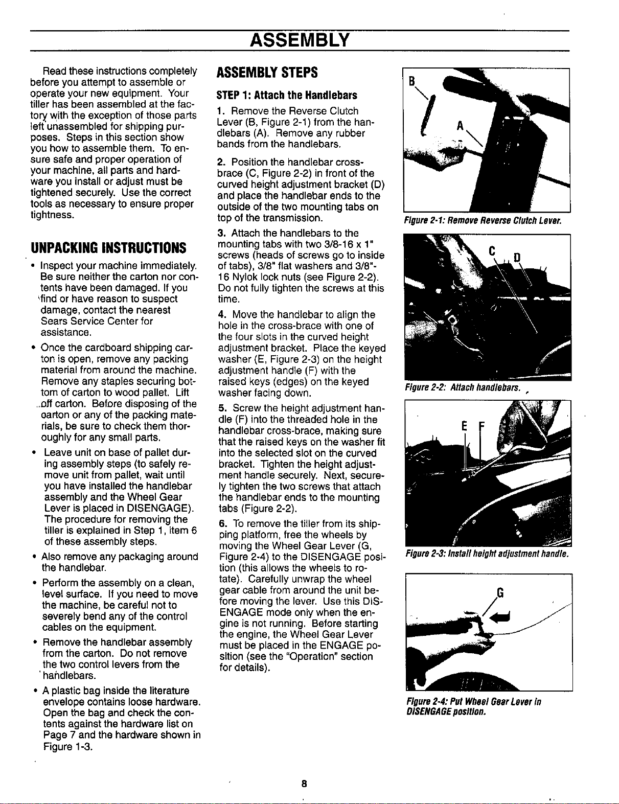
STEP 1: Attach the Handlebars
1. Remove the Reverse Clutch
Lever (B, Figure 2-1) from the han-
dlebars (A). Remove any rubber
bands from the handlebars.
2. Position the handlebar cross-
brace (C, Figure 2-2) in front of the
curved height adjustment bracket (D)
and place the handlebar ends to the
outside of the two mounting tabs on
top of the transmission.
3, Attach the handlebars to the
mounting tabs with two 3/8-16 x 1"
screws (heads of screws go to inside
of tabs), 3/8" flat washers and 3/8"-
16 Nylok lock nuts (see Figure 2-2).
Do not fully tighten the screws at this
time.
4. Move the handlebar to align the
hole in the cross-brace with one of
the four slots in the curved height
adjustment bracket. Place the keyed
washer (E, Figure 2-3) on the height
adjustment handle (F) with the
raised keys (edges) on the keyed
washer facing down.
5. Screw the height adjustment han-
dle (F) into the threaded hole in the
handlebar cross-brace, making sure
that the raised keys on the washer fit
into the selected slot on the curved
bracket. Tighten the height adjust-
ment handle securely. Next, secure-
ly tighten the two screws that attach
the handlebar ends to the mounting
tabs (Figure 2-2).
6. To remove the tiller from its ship-
ping platform, free the wheels by
moving the Wheel Gear Lever (G,
Figure 2-4) to the DISENGAGE posi-
tion (this allows the wheels to ro-
tate). Carefully unwrap the wheel
gear cable from around the unit be-
fore moving the lever. Use this DIS-
ENGAGE mode only when the en-
gine is not running. Before starting
the engine, the Wheel Gear Lever
must be placed in the ENGAGE po-
sition (see the "Operation" section
for details).
Figure2.1:RemoveReverseClutchLever.
D
Figure2-2: Attachhandlebars.,
E F
Figure2-3:Installheightadjustmenthandle.
Figure2-4:PutWheelGearLeverIn
DISENGAGEposition.
ASSEMBLY
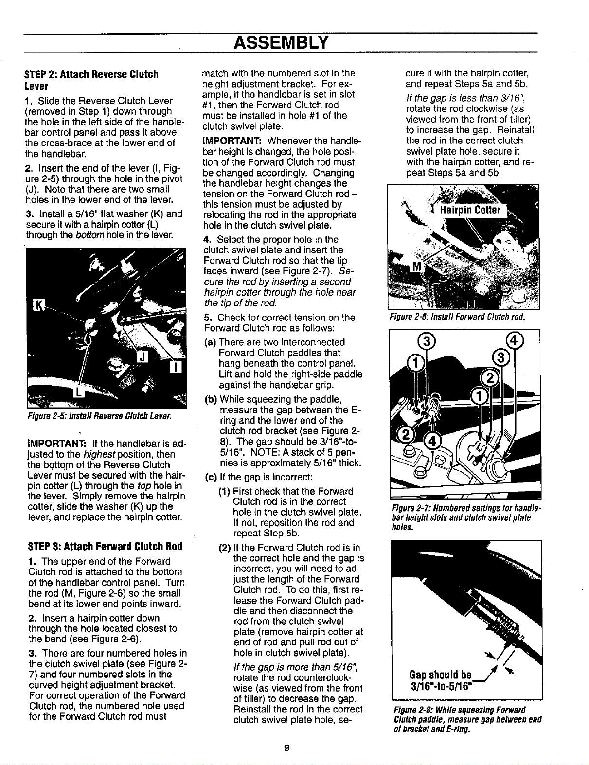
STEP2: AttachReverseClutch
Lever
1. Slide the Reverse Clutch Lever
(removed in Step 1) down through
the hole in the left side of the handle-
bar control panel and pass it above
the cross-brace at the lower end of
the handlebar.
2. Insert the end of the lever (I, Fig-
ure 2-5) through the hole in the pivot
(J). Note that there are two small
holes in the lower end of the lever.
3. Install a 5/16" flat washer (K) and
secure it with a hairpin cotter (L)
throughthe bottomholein the lever.
Figure2-5:InstaNReverseClutchLever.
IMPORTANT: If the handlebar is ad-
justed to the highest position, then
the bottq_mof the Reverse Clutch
Lever must be secured with the hair-
pin cotter (L) through the top hole in
the lever. Simply remove the hairpin
cotter, slide the washer (K) up the
lever, and replace the hairpin cotter.
STEP3: AttachForwardClutchRod
1. The upper end of the Forward
Clutch rod is attached to the bottom
of the handlebar control panel. Turn
the rod (M, Figure 2-6) so the small
bend at its lower end points inward.
2. Insert a hairpin cotter down
through the hole located closest to
the bend (see Figure 2-6).
3. There are four numbered holes in
the i_ldtchswivel plate (see Figure 2-
7) and four numbered slots in the
curved height adjustment bracket.
For correct operation of the Forward
Clutch rod, the numbered hole used
for the Forward Clutch rod must
match with the numbered slot in the
height adjustment bracket. For ex-
ample, if the handlebar is set in slot
#1, then the Forward Clutch rod
must be installed in hole #1 of the
clutch swivel plate.
IMPORTANT: Whenever the handle-
bar heightischanged, the hole posi-
tion of the Forward Clutch rod must
be changed accordingly. Changing
the handlebar height changes the
tension on the Forward Clutch rod-
this tension must be adjusted by
relocating the rod in the appropriate
hole in the clutch swivel plate.
4. Select the proper hole in the
clutch swivel plate and insert the
Forward Clutch rod so that the tip
faces inward (see Figure 2-7). Se-
cure the rod by inserting a second
hairpin cotter through the hole near
the tip of the rod.
5. Check for correct tension on the
Forward Clutch rod as follows:
(a) There are two interconnected
Forward Clutch paddles that
hang beneath the control panel.
Lift and hold the right-side paddle
against the handlebar grip.
(b) While squeezing the paddle,
measure the gap between the E-
ring and the lower end of the
clutch rod bracket (see Figure 2-
8). The gap should be 3/16"-to-
5/16". NOTE: A stack of 5 pen-
nies is approximately 5/16" thick.
(c) If the gap is incorrect:
(1) First check that the Forward
Clutch rod is in the correct
hole in the clutch swivel plate.
If not, reposition the rod and
repeat Step 5b.
(2) If the Forward Clutch rod is in
the correct hole and the gap is
incorrect, you will need to ad-
just the length of the Forward
Clutch rod. To do this, first re-
lease the Forward Clutch pad-
dle and then disconnect the
rod from the clutch swivel
plate (remove hairpin cotter at
end of rod and pull rod out of
hole in clutch swivel plate).
If the gap is more than 5/16",
rotate the rod counterclock-
wise (as viewed from the front
of tiller) to decrease the gap.
Reinstall the rod in the correct
clutch swivel plate hole, se-
cure it with the hairpin cotter,
and repeat Steps 5a and 5b.
If the gap is less than 3/16",
rotate the rod clockwise (as
viewed from the front of tiller)
to increase the gap. Reinstall
the rod in the correct clutch
swivel plate hole, secure it
with the hairpin cotter, and re-
peat Steps 5a and 5b.
Figure2-6: Install ForwardClutchrod.
Figure2-7:Numberedsettingsforhandle-
barheightslotsandclutchswivelplate
holes.
Gapshouldbej
3/16"-to-5/'16"
Figure2-8. WhilesqueezingForward
Clutchpaddle,measuregapbetweenend
ofbracketandE.ring.
9
ASSEMBLY
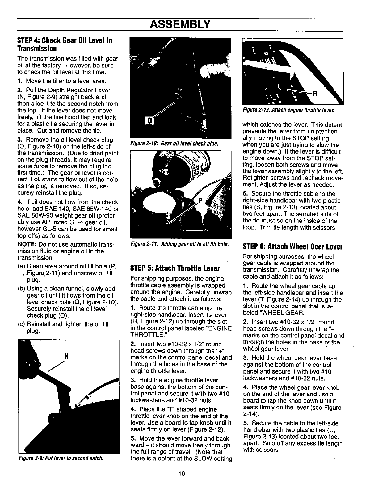
STEP4:CheckGearOilLevelin
TranS'm[ssion
The transmission was filled with gear
oil at the factory. However, be sure
to check the oil level at this time.
1. Move the tiller to a level area.
2. Pull the Depth Regulator Lever
(N, Figure 2-9) straight back and
then slide it to the second notch from
the top. If the lever does not move
freely, lift the tine hood flap and look
for a plastic tie securing the lever in
place. Cut and remove the tie.
3. Remove the oil level check plug
(O, Figure 2-10) on the left-side of
the transmission. (Due to dried paint
on the plug threads, it may require
some force to remove the plug the
first time.) The gear oil level is cor-
rect if oil starts to flow out of the hole
as the plug is removed. If so, se-
curely reinstall the plug.
4. If oil does not flow from the check
hole, add SAE 140, SAE 85W-140 or
SAE 80W-90 weight gear oil (prefer-
ably use API rated GL-4 gear oil,
however GL-5 can be used for small
top-offs) as follows:
NOTE: Do not use automatic trans-
mission fluid or engine oil in the
transmission.
(a) Clean area around oil fill hole (P,
,,.Figure,2-11) and unscrew oil fill
plug.
(b) Using a clean funnel, slowly add
gear oil until itflows from the oil
level check hole (O, Figure 2-10).
Securely reinstall the oil level
check plug (O).
(c) Reinstall and tighten the oilfill
plug.
Figure2.9:PutleverInsecondnotch.
Figure2.10: Gearoillevelcheckplug.
Figure2-11: Addinggearoilin o/Ifill hole.
STEP5:AttachThrottle Lever
For shipping purposes, the engine
throttle cable assembly is wrapped
around the engine. Carefully unwrap
the cable and attach it as follows:
1. Route the throttle cable up the
right-side handlebar. Insert its lever
(R, Figure 2-12) up through the slot
in the control panel labeled "ENGINE
THROTTLE."
2. Insert two #10-32 x 1/2" round
head screws down through the "+"
marks on the control panel decal and
through the holes in the base of the
engine throttle lever.
3. Hold the engine throttle lever
base against the bottom of the con-
trol panel and secure it with two #10
Iockwashers and #10-32 nuts.
4. Place the "T" shaped engine
throttle lever knob on the end of the
lever. Use a board to tap knob until it
seats firmly on lever (Figure 2-12).
5. Move the lever forward and back-
ward - it should move freely through
the full range of travel. (Note that
there is a detent at the SLOW setting
Figure2.12:Attachenginethrottlelever.
which catches the lever. This detent
prevents the lever from unintention-
ally moving to the STOP setting
when you are just trying to slow the
engine down.) If the lever is difficult
to move away from the STOP set-
ting, loosen both screws and move
the lever assembly slightly to the left.
Retighten screws and recheck move-
ment. Adjust the lever as needed.
6. Secure the throttle cable to the
right-side handlebar with two plastic
ties (S, Figure 2-13) located about
two feet apart. The serrated side of
the tie must be on the inside of the
loop. Trim tie length with scissors.
STEP6: AttachWheelGearLever
For shipping purposes, the wheel
gear cable is wrapped around the
transmission. Carefully unwrap the
cable and attach it as follows:
1. Route the wheel gear cable up
the left-side handlebar and insert the
lever (T, Figure 2-14) up through the
slot in the control panel that is la-
beled "WHEEL GEAR."
2. Insert two #10-32 x 1/2" round
head screws down through the "+"
marks on the control panel decal and
through the holes in the base of the
wheel gear lever. '....
3. Hold the wheel gear lever base
against the bottom of the control
panel and secure it with two #10
Iockwashers and #10-32 nuts.
4. Place the wheel gear lever knob
on the end of the lever and use a
board to tap the knob down until it
seats firmly on the lever (see Figure
2-14).
5. Secure the cable to the left-side
handlebar with two plastic ties (U,
Figure 2-13) located about two feet
apart. Snip off any excess tie length
with scissors.
10
,, ASSEMBLY
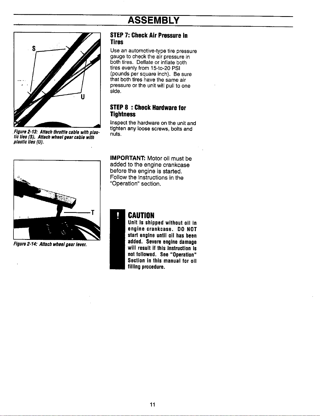
S
.Figure2.13. Attachthrottle cable withplas-
tic ties (S). Attachwheel gear cable with
plastic ties (U).
STEP7:CheckAirPressurein
Tires
Use an automotive-type tire pressure
gauge to check the air pressure in
both tires. Deflate or inflate both
tires evenly from 15-to-20 PSI
(pounds per square inch). Be sure
that both tires have the same air
pressure or the unit witl pull to one
side.
STEP8 : CheckHardwarefor
Tightness
Inspect the hardware on the unit and
tighten any loose screws, bolts and
nuts.
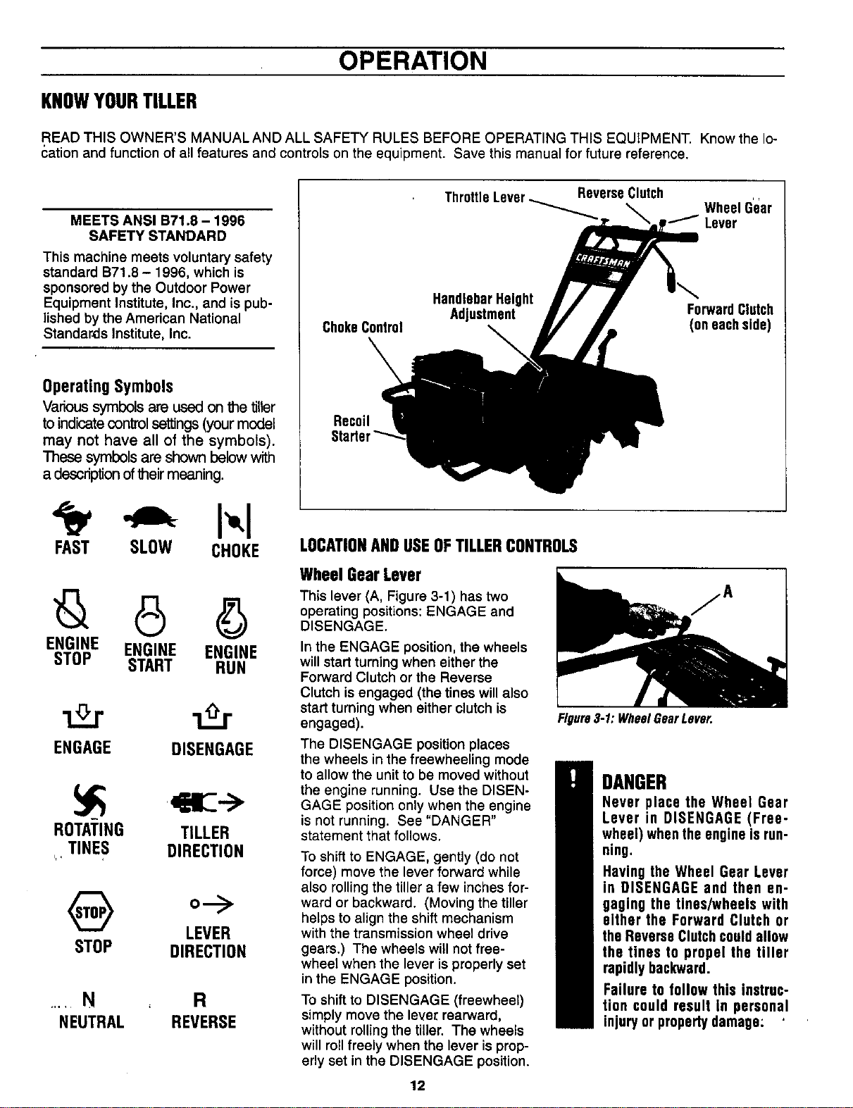
Figure2-14: Attachwheelgearlever.
IMPORTANT" Motor oil must be
added to the engine crankcase
before the engine is started.
Follow the instructions in the
"Operation" section.
CAUTION
Unit is shipped without oil in
engine crankcase. DO NOT
start engine until oll has been
added. Severe engine damage
will result if this instruction is
net followed. See "Operation"
Section in this manual for oil
filling procedure.
11
OPERATION
KNOWYOURTILLER
READ THIS OWNER'S MANUALAND ALL SAFETY RULES BEFORE OPERATING THIS EQUIPMENT. Know the lo-
cation and function of all features and controls on the equipment. Save this manual for future reference.
MEETS ANSI B71.8 - 1996
SAFETY STANDARD
This machine meets voluntary safety
standard B71.8 - 1996, which is
sponsored by the Outdoor Power
Equipment Institute, Inc., and is pub-
lished by the American National
Standards Institute, Inc.
Operating Symbols
Varioussymbols areusedon the tiller
toindicatecontrolsettings(your model
may not have all of the symbols).
These symbols are shown belowwith
a descriptionoftheirmeaning.
FAST SLOW CHOKE
ENGINE ENGINE ENGINE
STOP START RUN
z2.r
ENGAGE DISENGAGE
ROTATING TILLER
TINES DIRECTION
ip,
o--->
LEVER
STOP DIRECTION
..... N R
NEUTRAL REVERSE
ReverseClutch
Wheel G'ear
_Lever
ChokeControl
HandlebarHeight
Adjustment
ForwardClutch
(on eachside)
Recoil
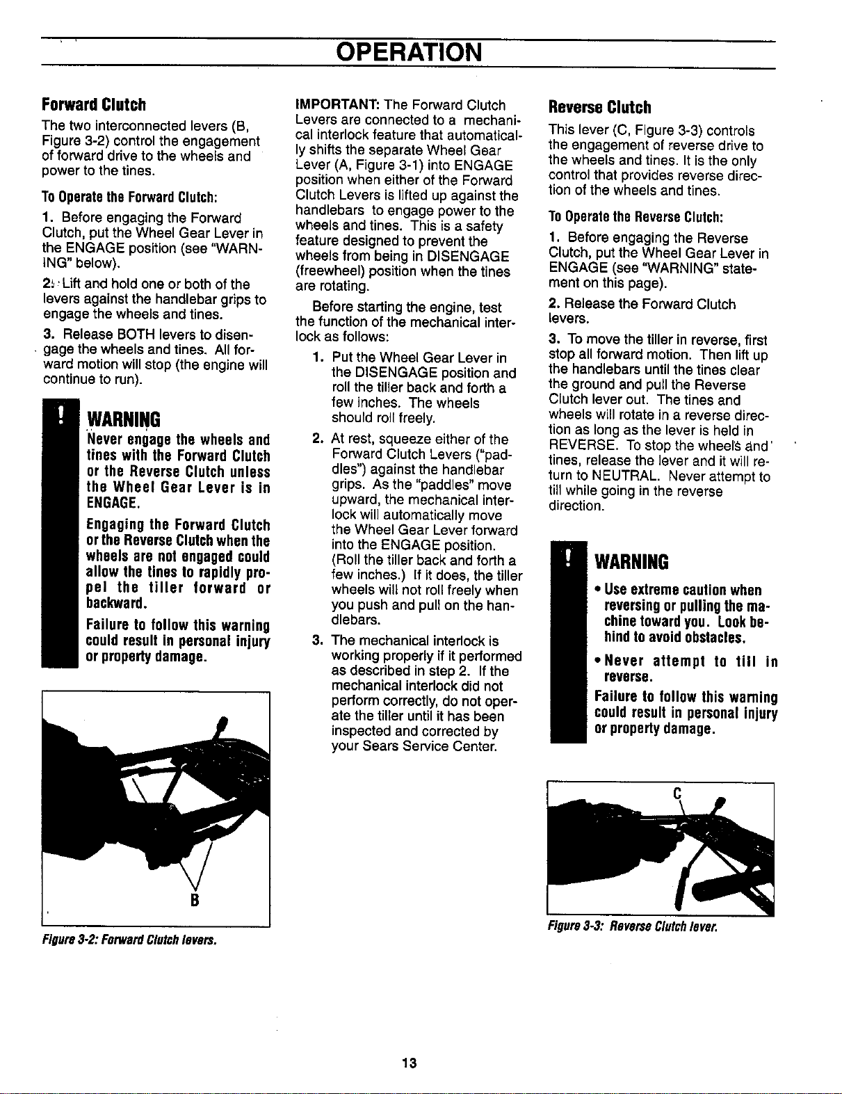
LOCATIONANDUSEOFTILLERCONTROLS
WheelGearLever
This lever (A, Figure 3-1) has two
operating positions: ENGAGE and
DISENGAGE.
In the ENGAGE position, the wheels
will start turning when either the
Forward Clutch or the Reverse
Clutch is engaged (the tines will also
start turning when either clutch is
engaged).
The DISENGAGE position places
the wheels in the freewheeling mode
to allow the unit to be moved without
the engine running. Use the DISEN-
GAGE position only when the engine
is not running. See "DANGER"
statement that follows.
To shift to ENGAGE, gently (do not
force) move the lever forward while
also rolling the tiller a few inches for-
ward or backward. (Moving the tiller
helps to align the shift mechanism
with the transmission wheel drive
gears.) The wheels will not free-
wheel when the lever is properly set
in the ENGAGE position.
To shift to DISENGAGE (freewheel)
simply move the lever, rearward,
without rolling the tiller. The wheels
will roll freely when the lever is prop-
erly set in the DISENGAGE position.
Figure3-1:WheelGearLever.
DANGER
Never place the Wheel Gear
Lever in DISENGAGE (Free-
wheel) when the engine is run-
ning.
Having the Wheel Gear Lever
in DISENGAGE and then en-
gaging the tines/wheels with
either the Forward Clutch or
the Reverse Clutchcould allow
the tines to propel the tiller
rapidly backward.
Failure to follow this instruc-
tion could result in personal
injury or property damage:
12
' ' OPERATION
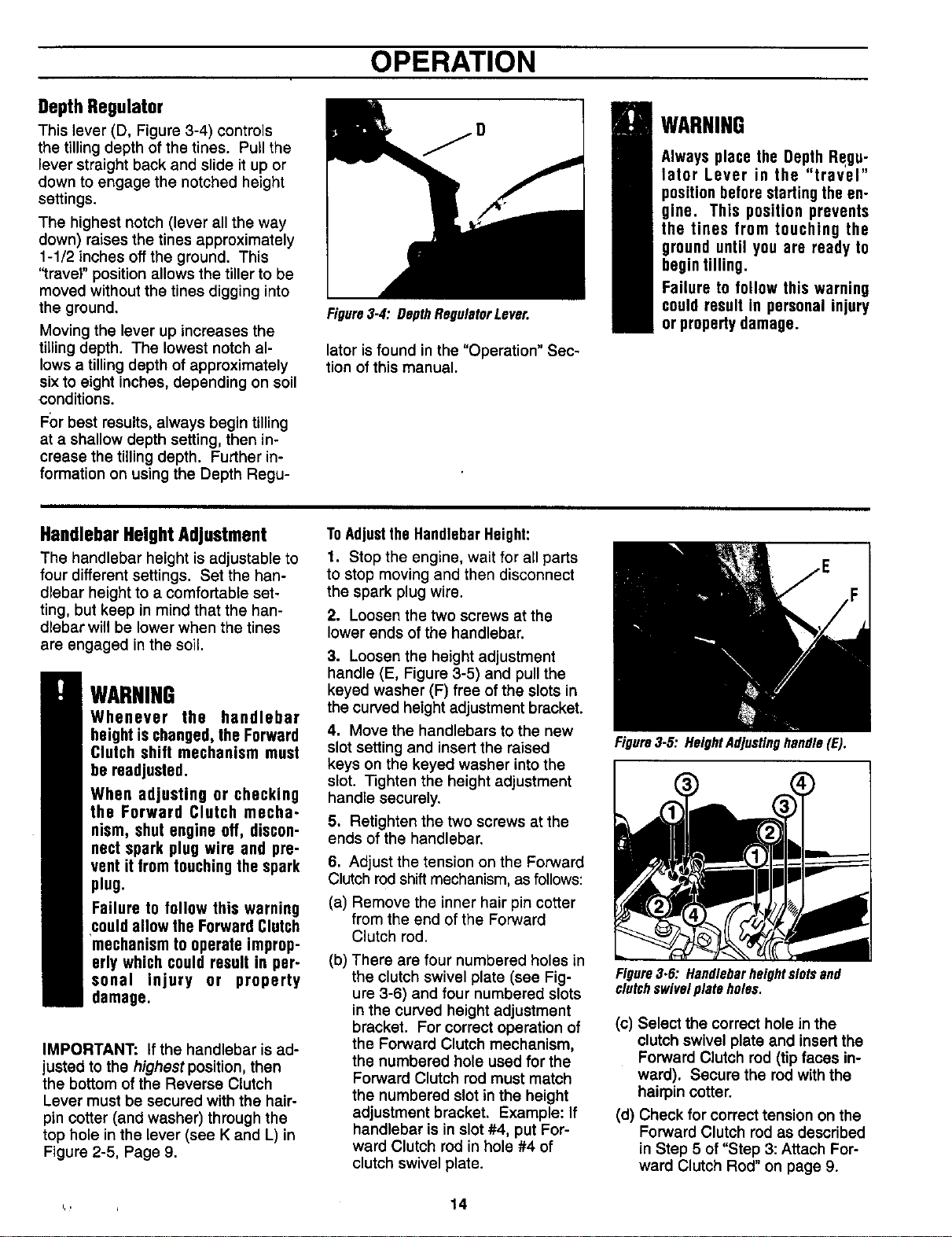
ForwardClutch
The two interconnected levers (B,
Figure 3-2) control the engagement
of forward drive to the wheels and
power to the tines.
To Operatethe ForwardClutch:
1, Before engaging the Forward
Clutch, put the Wheel Gear Lever in
the ENGAGE position (sea "WARN-
ING" below).
2_, Lift and hold one or both of the
levers against the handlebar grips to
engage the wheels and tines.
3. Release BOTH levers to disen-
gage the wheels and tines. All for-
ward motion will stop (the engine will
continue to run).
WARNING
Never engage the wheels and
tines with the Forward Clutch
or the Reverse Clutch unless
the Wheel Gear Lever is in
ENGAGE.
Engaging the Forward Clutch
or the Reverse Clutchwhen the
wheels are not engaged could
allow the tines to rapidly pro-
pe] the tiller forward or
backward.
Failure to follow this warning
could result in personal injury
or propertydamage.
B
Figure3-2".ForwardClutchlevers.
IMPORTANT: The Forward Clutch
Levers are connected to a mechani-
cal interlock feature that automatical-
ly shifts the separate Wheel Gear
Lever (A, Figure 3-1) into ENGAGE
position when either of the Forward
Clutch Levers is lifted up against the
handlebars to engage power to the
wheels and tines. This is a safety
feature designed to prevent the
wheels from being in DISENGAGE
(freewheel) position when the tines
are rotating.
Before starting the engine, test
the function of the mechanical inter-
lock as follows:
.
o
Put the Wheel Gear Lever in
the DISENGAGE position and
roll the tiller back and forth a
few inches. The wheels
should roll freely.
At rest, squeeze either of the
Forward Clutch Levers ("pad-
dles") against the handlebar
grips. As the "paddles" move
upward, the mechanical inter-
lock will automatically move
the Wheel Gear Lever forward
into the ENGAGE position.
(Roll the tiller back and forth a
few inches.) If it does, the tiller
wheels will not roll freely when
you push and pull on the han-
dlebars.
. The mechanical interlock is
working properly if it performed
as described in step 2. If the
mechanical interlock did not
perform correctly, do not oper-
ate the tiller until it has been
inspected and corrected by
your Sears Service Center.
ReverseClutch
This lever (C, Figure 3-3) controls
the engagement of reverse drive to
the wheels and tines. It is the only
control that provides reverse direc-
tion of the wheels and tines.
ToOperatethe ReverseClutch:
1. Before engaging the Reverse
Clutch, put the Wheel Gear Lever in
ENGAGE (see "WARNING" state-
ment on this page).
2. Release the Forward Clutch
levers.
3. To move the tiller in reverse, first
stop all forward motion. Then lift up
the handlebars until the tines clear
the ground and pull the Reverse
Clutch lever out. The tines and
wheels will rotate in a reverse direc-
tion as long as the lever is held in
REVERSE. To stop the wheel'S;_.nd'
tines, release the lever and it will re-
turn to NEUTRAL. Never attempt to
till while going in the reverse
direction.
WARNING
• Use extreme cautionwhen
reversing or pulling the ma-
chine towardyou. Lookbe-
hind to avoid obstacles,
• Never attempt to till in
reverse.
Failure to follow this warning
could result in personal injury
or property damage.
Figure3-3".ReverseClutchlever.
13
OPERATION
DepthRegulator
This lever (D, Figure 3-4) controls
the tilling depth of the tines. Pull the
lever straight back and slide it up or
down to engage the notched height
settings.
The highest notch (lever all the way
down) raises the tines approximately
1-1/2 inches offthe ground. This
"travel" position allows the tiller to be
moved without the tines digging into
the ground.
Moving the lever up increases the
tilling depth. The lowest notch al-
lows a tilling depth of approximately
sixto eight inches, depending on soil
conditions.
F_)rbest results, always begin tilling
at a shallow depth setting, then in-
crease the tilling depth. Further in-
formation on using the Depth Regu-
Figure3.4: DepthRegulatorLever.
later isfound in the "Operation" Sec-
tion of this manual.
WARNING
Always place the Depth Regu-
lator Lever in the "travel"
position before starting the en-
gine. This position prevents
the tines from touching the
ground until you are ready to
begin tilling.
Failure to follow this warning
could result in personal injury
or propertydamage.
HandlebarHeightAdjustment
The handlebar height is adjustable to
four different settings. Set the han-
dlebar height to a comfortable set-
ting, but keep in mind that the han-
dlebar will be lower when the tines
are engaged in the soil.
WARNING
Whenever the handlebar
height is changed,the Forward
Clutch shift mechanism must
be readjusted.
When adjusting or checking
the Forward Clutch mecha-
nism, shut engine off, discon-
nect spark plug wire and pre-
vent it from touching the spark
plug.
Failure to follow this warning
could allow the Forward Clutch
mechanism to operate improp-
erly which could result in per-
sonal injury or property
damage.
IMPORTANT: If the handlebar is ad-
justed to the highest position, then
the bottom of the Reverse Clutch
Lever must be secured with the hair-
pin cotter (and washer) through the
top hole in the lever (see K and L) in
Figure 2-5, Page 9.
ToAdjustthe HandlebarHeight:
1. Stop the engine, wait for all parts
to stop moving and then disconnect
the spark plug wire.
2. Loosen the two screws at the
lower ends of the handlebar.
3. Loosen the height adjustment
handle (E, Figure 3-5) and pull the
keyed washer (F) free ofthe slots in
the curved height adjustment bracket.
4. Move the handlebars to the new
slot setting and insert the raised
keys on the keyed washer into the
slot. nghten the height adjustment
handle securely.
5. Retighten the two screws at the
ends of the handlebar.
6. Adjust the tension on the Forward
Clutch rodshift mechanism, as follows:
(a) Remove the inner hair pin cotter
from the end of the Forward
Clutch rod.
(b) There are four numbered holes in
the clutch swivel plate (see Fig-
ure 3-6) and four numbered slots
in the curved height adjustment
bracket. For correct operation of
the Forward Clutch mechanism,
the numbered hole used for the
Forward Clutch rod must match
the numbered slot in the height
adjustment bracket. Example: If
handlebar is in slot #4, put For-
ward Clutch rod in hole #4 of
clutch swivel plate.
Figure3.5: HeightAdjustinghandle(E).
Figure3.6: Handlebarheight slatsand
clutchswivulplate holes.
(c) Select the correct hole in the
clutch swivel plate and insertthe
Forward Clutch rod (tip faces in-
ward). Secure the rodwith the
hairpin cotter.
(d) Check for correct tension on the
Forward Clutch rodas described
in Step 5 of "Step 3: Attach For-
ward Clutch Rod" on page 9.
,., 14
OPERATION
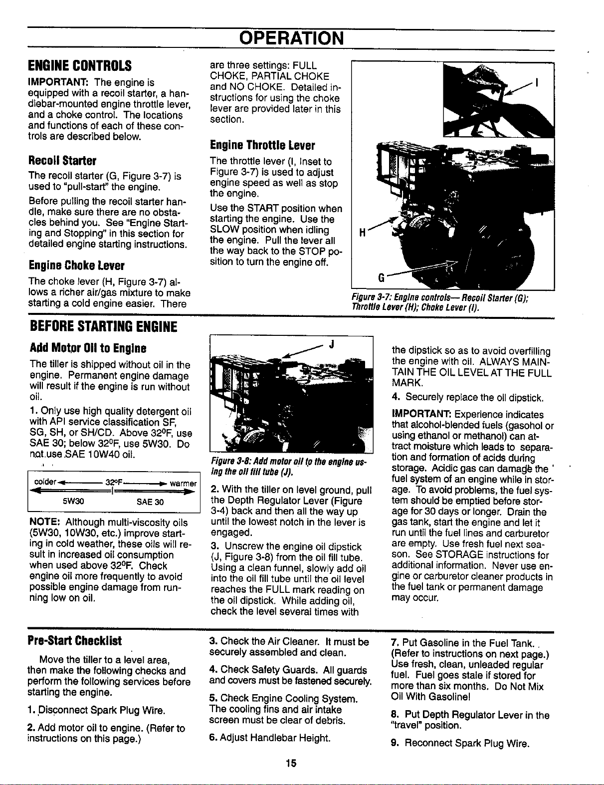
ENGINECONTROLS
IMPORTANT: The engine is
equipped with a recoil starter, a han-
dlebar-mounted engine throttle lever,
and a choke control The locations
and functions of each of these con-
trols are described below.
RecoilStarter
The recoil starter (G, Figure 3-7) is
used to "pull-start" the engine.
Before pulling the recoil starter han-
dle, make sure there are no obsta-
cles behind you. See "Engine Start-
ing and Stopping" in this section for
detailed engine starting instructions.
EngineChoke Lever
are three settings: FULL
CHOKE, PARTIAL CHOKE
and NO CHOKE. Detailed in-
structions for using the choke
lever are provided later in this
section.
EngineThrottleLever
The throttle lever (I, Inset to
Figure 3-7) is used to adjust
engine speed as well as stop
the engine.
Use the START position when
starting the engine. Use the
SLOW position when idling
the engine. Pull the lever all
the way back to the STOP po-
sition to turn the engine off.
The choke lever (H, Figure 3-7) al-
lows a richer air/gas mixture to make
starting a cold engine easier. There
Figure3-7:Enginecontrols--RecoilStarter(G);
ThrottleLever(H);ChokeLever(I).
BEFORESTARTINGENGINE
AddMot_)r011to Engine
The tiller is shipped without oil in the
engine. Permanent engine damage
will result if the engine is run without
oil.
1. Only use high quality detergent oil
with API service classification SF,
SG, SH, or SH/CD. Above 32OF,use
SAE 30; below 320F, use 5W30. Do
nat.use SAE 10W40 oil
) ,
[ colder.._----._- 32OF-.-----.._ warmer]
5W30 I SAE30 ) ]/
NOTE: Although multi-viscosity oils
(5W30, 10W30, etc.) improve start-
ing in cold weather, these oils will re-
sult in increased oil consumption
when used above 32OF. Check
engine oil more frequently to avoid
possible engine damage from run-
ning low on oil.
Figure3-8:Addmotoroiltotheengineus.
ingtheoilfill tube(J).
2. With the tiller on level ground, pull
the Depth Regulator Lever (Figure
3-4) back and then all the way up
until the lowest notch in the lever is
engaged.
3. Unscrew the engine oil dipstick
(J, Figure 3-8) from the oil fill tube.
Using a clean funnel, slowly add oil
into the oil fill tube until the oil level
reaches the FULL mark reading on
the oil dipstick. While adding oil,
check the level several times with
the dipstick so as to avoid overfilling
the engine with oil. ALWAYS MAIN-
TAIN THE OIL LEVEL AT THE FULL
MARK.
4. Securely replace the oil dipstick.
IMPORTANT: Experience indicates
that alcohol-blended fuels (gasohol or
using ethanol or methanol) can at-
tract moisture which leads to separa-
tion and formation of acids during
storage. Acidic gas can dama_j_ the '
fuel system of an engine while in stor-
age. To avoid problems, the fuel sys-
tem should be emptied before stor-
age for 30 days or longer. Drain the
gas tank, start the engine and let it
run until the fuel lines and carburetor
are empty. Use fresh fuel next sea-
son. See STORAGE instructions for
additional information. Never use en-
gine or carburetor cleaner products in
the fuel tank or permanent damage
may occur.
Pre-StartChecklist
Move the tiller to a level area,
then make the following checks and
perform the following services before
starting the engine.
1. Disconnect Spark Plug Wire.
2. Add motor oil to engine. (Refer to
instructionson this page.)
3. Check the Air Cleaner. It must be
securely assembled and clean.
4. Check Safety Guards. All guards
and covers must be fastened securely.
5. Check Engine Cooling System.
The cooling fins and air intake
screen must be clear of debris.
6. Adjust Handlebar Height.
15
7, Put Gasoline in the Fuel Tank..
(Refer to instructionson next page.)
Use fresh, clean, unleaded regular
fuel. Fuel goes stale if stored for
more than six months. Do Not Mix
Oil With Gasoline!
8. Put Depth Regulator Lever in the
"travel" position.
9. Reconnect Spark Plug Wire.

OPERATION
Fill Fuel Tank
The engine must be off and cool be-
fore removing fuel fill cap (Figure 3-9).
Clean area around fuel fill cap and
then remove fill cap. Be sure to use
clean, fresh unleaded regular gaso-
line. Do not mix oil with gasoline.
NOTE: Do not use gasoline contain-
ing methanol (wood alcohol). Never
use stale gasoline left over from last
season or unused for long periods.
Using a funnel or spout, fill tank to
within 1/2" below the bottom of the
fuel tank filler neck to prevent spills
and to allow for fuel expansion. In-
stall the fill cap securely and wipe up
any spilled gasoline.
Figure3-9: Fill thefuel lank(K).
DANGER
Gasoline is highly flammable
and its vaporsexplosive. Fol-
low these safety practices to
prevent injury from fire or ex-
plosion:
• Never fill tank if engine is
runningor hot from use. Let
engine and mufflercooldown
beforerefueling.
• Do not permit open flames,
.sparks,matchesorsmokingin
fuelingarea.
• Fill fuel tank outdoors in a
well-ventilated area. Wipe
up any fuel spills and move
tiller away fromfumesbefore
startingthe engine.
• Use only an approved fuel
container and lock it safely
away fromchildren.
• Store fuel and the tiller in a
well-ventilated area. Do not
store fuel or tiller where fuel
vapors may reach an open
flame or spark, or an ignition
source (a hot water heater,
furnace, clothes dryer, elec-
tric motor,orthe like).
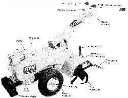
• Letenginecoolbeforestoring.
ThrottleLever
ReverseClutch
WheelGear
J Lever
HandlebarHeight
Adjustment
Choke
Control
Recoil
Starter
ForwardClutch
(oneachside)
Depth
Regulator
Figure3-I0
WARNING
Before operating your ma-
chine, carefully read and un-
derstand all Safety and Oper-
ation instructionsin this Man-
ual and on the decals on the
machine.
Failure to .follow these in-
structions can result in seri-
ous personal injury.
STOPPINGAND
STARTINGTHEENGINE
Break-InOperation
Perform the following maintenance
during the first hours of new opera-
tion (see "Customer Responsibilities"
section of this manual).
1. Change engine oil after first 2
hours of new engine operation.
2. Check for loose or missing hard-
ware on unit. Tighten or replace as
needed.
Stoppingthe Engine
The following steps describe how to
stop the engine.
1. To stop the wheels and tines, re-
lease the Forward Clutch levers or
the Reverse Clutch lever (whichever
control is in use).
16
2. To stop the engine, move the En-
gine Throttle Lever to the STOP
position.
Startingthe Engine
The following steps describe how to
start the engine. Do not attempt to
engage the tines or wheels until
you have read all of the operating
instructions in this Section. Also
review the safety rules in the Safe-
ty Section.
1. Complete the '?re-Start Check-
list".
2. Put the Wheel Gear Lever (Figure
3-10) in the ENGAGE position.
3. Put the Depth Regulator Lever
(see Figure 3-10) in the "travel" posi-
tion (lever all the way down) so that
the tines are clear of the ground.
4. Release all controls on the tiller.
5. If engine is equipped with a fuel
shutoff valve, turn valve to the open
position.
6. Put the Engine Throttle Lever
(Figure 3-10) in the START setting.
7. Choke the engine (see Figure 3-
10) as follows: Move choke lever to
FULL CHOKE position (move in di-
rection of arrowhead located on
lever).
NOTE: If restarting a warm engine
after a short shutdown, move choke
lever to NO CHOKE position instead.

i,
OPERATION
CAUTION
To help prevent serious
personal injury or damage to
equipment:
• Before starting engine, put
Wheel GearLever in ENGAGE
position.
• Before starting engine, put
ForwardClutchLeversand Re-
verse ClutchLever in neutral
(disengaged)positionsby re-
leasinglevers.
• Nevermn engineindoorsor in
enclosed,poorlyventilatedar-
eas. Engineexhaustcontains
carbon monoxide, an odor-
less,colorlessanddeadlygas.
• Avoid engine muffler and
nearbyareas. Temperatures
in these areas may exceed
150o1.
DANGER
GASOLINE IS HIGHLY
FLAMMABLE AND ITS VA-
PORSAREEXPLOSIVE.
Followgasolinesafetyrules in
this manual (see Safety Sec-
tion).
Failure to follow gasoline
safety instructionscan result
in serious personal injury
and propertydamage.
8. Pull recoil starter rope, as follows:
(a) Check behind you before
pulling the recoil starter handle.
Avoid contacting any obstacles
when pulling the handle. Place
one hand on the fuel tank to
....'stabilize the)unit when you pull
the starter handle.
(b) Pull recoil handle until you feel
resistance. Let rope rewind ful-
ly. Then pull rope out rapidly.
Maintain control of rope so it
slowly returns into starter
mechanism. This action may
need to be repeated several
times until the engine starts.
(c) When engine starts, gradually
move choke lever (on engines
so equipped) to 1/2 CHOKE un-
til engine runs smoothly and
then to NO CHOKE position. If
engine falters, move choke
lever to 1/2 CHOKE until en-
gine runs smoothly and then to
NO CHOKE position.
NOTE: If engine fails to start after 3
pulls, move choke lever to NO
CHOKE position and pull starter rope
again.
NOTE: If engine fires, but does not
continue to run, move choke lever to
FULL CHOKE and repeat instruc-
tions "a", "b", and "c" untilengine
starts.
OPERATINGTHETILLER
The following pages provide guide-
lines to using your tiller effectively
and safely in various gardening ap-
plications. Be sure to read "Tilling
Tips & Techniques" in this Section
before you actually put the tines into
the soil.
WARNING
Keep away Irom rotatingtines.
Rotating tines will cause seri-
ous personal injury.
1. Follow the "Pre-Start Checklist"
on Page 15. Be sure the Wheel
Gear Lever is in the ENGAGE
position.
2. Put the Depth Regulator
Lever in the '_traver' posi-
tion (lever all the way
down) so that the tines are
clear of the ground. Use
this position when practic-
ing with your tiller or when
moving to or from the gar-
den. When you are ready
to begin tilling, you must
move the Depth Regulator
Lever to the desired depth
setting (see "Tilling Tips &
Techniques").
17
3. Start the engine and allow it to
warm up. When warm, put throttle
control in fast speed setting.
4. For forward motion of the wheels
and tines:
(a) Pull the Forward Clutch lever
"paddles" up and hold them
against the handlebars. To
stop forward motion of the
wheels and tines, release the
"paddles."
(b) As the tilter moves forward, re-
lax and let the wheels pull the
unit along while the tines dig.
Walk behind and a little to one
side of the tiller. Use a light but
secure grip with one hand on
the handlebars, but keep your
arm loose. See Figure 3-11.
Let the tiller move ahead at its
own pace and do not push
down on the handlebars to try
and force the tiller to dig deeper
- this takes weight off the
wheels, reduces traction, and
causes the tines to try and pro-
pel the tiller.
Figure3-11:Useonehandtoguidetillerwhen
moving
OPERATION
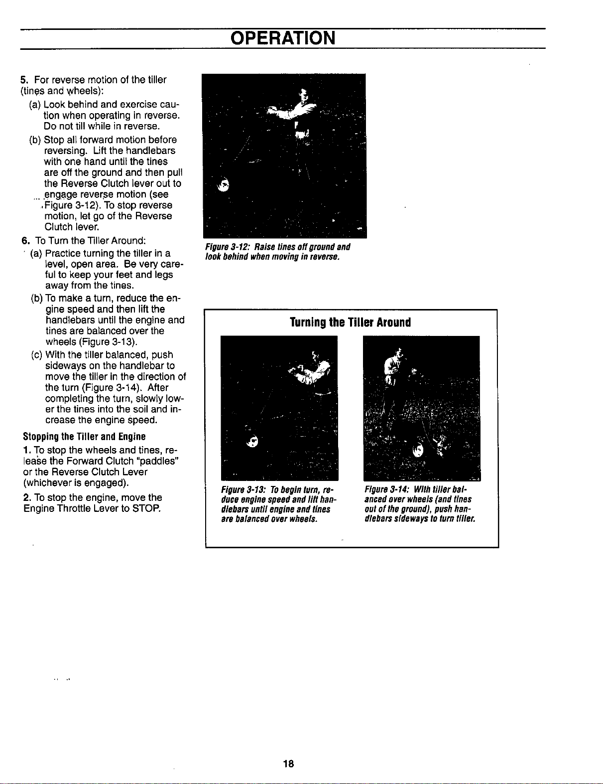
5. For reverse motion of the tiller
(tines and wheels):
(a) Look behind and exercise cau-
tion when operating in reverse.
Do not till while in reverse.
(b) Stop all forward motion before
reversing. Lift the handlebars
with one hand until the tines
are off the ground and then pull
the Reverse Clutch lever out to
....engage reverse motion (see
, Figure 3-12). To stop reverse
motion, let go of the Reverse
Clutch lever.
6. To Turn the Tiller Around:
(a) Practice turning the tiller in a
level, open area. Be very care-
ful to keep your feet and legs
away from the tines.
(b) To make a turn, reduce the en-
gine speed and then lift the
handlebars until the engine and
tines are balanced over the
wheels (Figure 3-13).
(c) With the tiller balanced, push
sideways on the handlebar to
move the tiller in the direction of
the turn (Figure 3-14). After
completing the turn, slowly low-
er the tines into the soil and in-
crease the engine speed.
StoppingtheTiller andEngine
1. To stop the wheels and tines, re-
lease the Forward Clutch "paddles"
or the Reverse Clutch Lever
(whichever is engaged).
2, To stop the engine, move the
Engine Throttle Lever to STOP.
Figure3-12: Raisetinesoffgroundand
lookbehindwhenmovinginreverse.
Turningthe Tiller Around
Figure3-13: Tobeginturn, re-
duceenginespeedandlift han-
dlebareuntilengineandtines
arebalancedoverwheels.
Figure3-14: Withtiller bal.
ancedoverwheels(andtines
outoftheground),pushhan-
dlebarssidewaystoturntiller.
18
OPERATION
TillingTips& Techniques
Letthetiller dothework
• While tiUing,relaxand letthe wheels
pull thetiller along whilethetines do
the digging. Walk on the sidethat is
' notyet finished (to avoid making foot-
prints in the freshly tilledsoil) and
lightly, butsecurely grip the handlebar
with just one hand. SeeFigure3-11.
• Avoidthe temptation to push down on
the handlebarsinan attempt to force
the tiller to dig deeper. Pushing down
on the handlebarstakesthe weight off
the poweredwheels,causingthem to
losetraction. Without the wheels help-
ing to hold the tiller back,the tines will
attempt to propel the tiller- causing
the_illerto move rapidly backtoward
you. (Sometimes,slight downward
pressure on the handlebarswill help
getthrough a particularly tough section
of sod or unbroken ground, but in
most casesthis won't benecessaryat
all.)
Tilling depths
• Thisis a CRT(counter-rotating tine)
tiller. Asthe wheels pull forward, the
tines rotate backward. This createsan
"uppercut" tine action which digs
deeply,uprooting soil and weeds.
Don't overloadthe engine,but dig as
deeplyas possible on each pass. On
later passes,the wheels may tendto
spinin the soft dirt. Helpthem along
by lifting slightly onthe handlebar (us-
ing just one hand, palm upward, works
most easily).
• Wateringthe gardenareaa few days
prior to tilling willmaketiltingeasier,as
will letting the newly worked soil rest
for a dayor two before making a final,
deep tilling pass.
•When cultivating (breakingupthe sur-
face soil aroundplantsto help destroy
weeds),adjust thetines to dig only1-
U2"to 2"deep. Usingshallowtilling
depthshelps preventInjuryto plants
whoseroots oftengrowclosetothesur-
face. If needed,lift up on thehandlebars
slightlyto preventthetinesfrom digging
toodeeply. Cultivatingon a regularbasis
notonlyeliminatesweeds,italsoloosens
andaeratesthesoilfor bettermoisture
absorptionandfasterplantgrowth.)
Avoidtillingsoggy, wet soil
Tillingwetsoil oftenresults in large,
hard clumps of soil that caninterfere
with planting. If time permits, wait a
dayor two after heavyrainsto allow
the soilto dry beforetilling. Testsoil
by squeezingit into a ball. Ifit com-
pressestoo easily,it istoo wet to till.
Avoidmakingfootprints
• Wheneverpossible,walk on the untilled
sideof the unitto avoid makingfoot-
prints in your freshly tiltedor cultivated
soil. Footprintscausesoil compaction
that canhamperroot penetrationand
contribute to soil erosion. Theycan
also "plant" unwantedweedseedsback
into thefreshly tilled ground.
Choosingcorrectwheel
andtine speed
With experience,you willfind the "just
right" tilling depth andtillingspeedcom-
bination that is best for your garden.
Setthe enginethrottle leverat a speedto
givethe engineadequatepowerandyet
allow it to operateatthe slowest possi-
blespeed...at leastuntil you have
achievedthe maximum tilling depth you
desire. Fasterenginespeeds may be de-
sirable when making final passes
through the seedbedor when cultivating.
Selection of the correct engine speed,in
relationto the tilling depth, will ensurea
sufficient powerlevelto do the job with-
out causing the engineto labor.
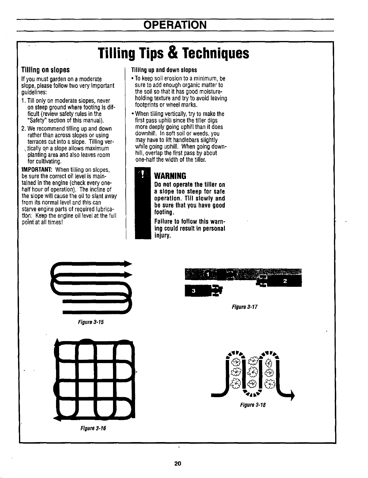
Suggestedtilling patterns
• Whenpreparing a seedbed,go over the
samepathtwice inthe first row, then
overlapone-halfthe tillerwidthon the
rest of the passes(seeFigure3-15).
Whenfinished in one direction, makea
second passat a right angleas shown
in Figure3-16. Overlapeachpassfor
best results (in very hard ground it
may takethree or four passesto thor-
oughly pulverizethe soil).
. If the gardensize will not permit
lengthwise andthen crosswise tilling,
then overlapthefirst passesby one-
half atiller width,followed by succes-
sive passesat one-quarterwidth (see
Figure3-17).
With planning, you canallow enough
room betweenrows to cultivate (see
Figure3-18). Leaveroom for the hood
width, plusenough extra room for fu-
ture piant growth.
Clearingthe tines
Thetines havea self-clearingaction
whicheliminatesmost tangling of debris
inthetines. However,occasionallydry
grass, stringy stalks or tough vines may
becometangled. Follow these proce-
dures to helpavoid tangling andto clean
the tines, if necessary.
• Toreducetangling, setthe depthregu-
lator deepenoughto get maximum
"chopping" action as thetines chop the
material againstthe ground. Also, try
to till under crop residues or cover
crops while they are green,moist and
tender.
•While powercomposting, try swaying
the handlebarsfrom sideto side (about
6"to 12"). This "fishtaiting" action of.
ten clearsthe tines of debris.
• If the proceduresabovedon't clear the
debris, it may be necessaryto remove
the debris by hand (a pocket knifewill
help you cut awaythe material).
WARNING
Before clearing the tines by
hand, stop the engine, al-
low all moving partsto stop
and disconnect the spark
plug wire,
Failure to follow this warn-
ing could result in personal
injury.
..... 19
,, . , ,
OPERATION
TillingTips& Techniques
Tillingonslopes
If you must gardenona moderate
slope, pleasefollow two very important
guidelines:
1.Till only on moderateslopes, never
on steepgroundwherefooting is dif-
ficult (review safetyrules in the
"Safety" section ofthis manual).
2.We recommendtilling upand down
ratherthan acrossslopes or using
terraces cut into a slope. Tilling vet-
,,_icallyqn a slopeallows maximum
plantingarea andalso leavesroom
for cultivating.
iMPORTANT:When tilling on slopes,
besurethecorrectoillevelismain-
tainedin theengine(checkevery one-
halfhourof operation).Theinclineof
theslopewillcausetheoilto slantaway
fromitsnormallevelandthis can
starveenginepartsofrequired lubrica-
tion: Keeptheengine oillevelatthefull
_01nt'at alltimes!
Tilling upand downslopes
• To keepsoil erosion to a minimum, be
sureto add enoughorganicmatterto
the soil sothatithasgoodmoisture-
holding textureand tryto avoidleaving
footprints orwheelmarks.
• Whentilling vertically,try to make the
first pass uphill sincethe tiller digs
moredeeplygoing uphill than it does
downhill. Insoft soil or weeds,you
may haveto lift handlebarsslightly
whilegoing uphill. Whengoingdown-
hill, overlapthe first pass by about
one-halfthe width of the tiller.
WARNING
Do not operate the tiller on
a slope too steep for safe
operation. Till slowly and
be sure that you have good
footing.
Failure to follow this warn-
ing could result in personal
injury.
Figure3.15
Figure3-17
A
1
!
!
Figure3-16
Figure3-18
20
OPERATION
LOADINGANDUNLOADING
THETILLER
WARNING
Loading and unloading the
tiller into a vehicle is poten-
tially hazardous and we don't
recommend doing so unless
absolutely necessary, as this
could result in personal injury
or propertydamage.
However, if you must load or
unload the tiller, follow the
guidelines given next.
• Before loading or unloading, stop
the engine, wait for all parts to stop
moving, disconnect the spark plug
wire and let the engine and muffler
cool. Move the spark plug wire
away from the spark plug.
• The tiller is too heavy (165 to 240
Ibs., depending on model) and
bulky to lift safely by one person.
Two or more people should share
the load.
• Use sturdy ramps and manually
(with engine shut off) roll the tiller
into and out of the vehicle. Two or
more people are needed to do this.
• Ramps must be strong enough to
support the combined weight of the
tiller and any handlers. The ramps
should provide good traction to pre-
vent slipping; they should have side
rails to guide the tiller along the
ramps; and they should have a
locking device to secure them to
the vehicle.
• The handlers should wear sturdy
footwear that will help to prevent
slipping.
• Position the loading vehicle so that
the ramp angle is as flat as possi-
ble (the less inclined the ramp, the
better). Turn the vehicle's engine
off and apply its parking brake.
• When going up ramps, stand in the
normal operating position and push
the tiller ahead of you. Have a per-
son at each side to turn the wheels.
• When going down ramps, walk
backward with the tiller following
you. Keep alert for any obstacles
behind you. Position a person at
each wheel to control the speed of
the tiller. Never go down ramps
tiller-first, as the tiller could tip for-
ward.
• Use wooden blocks to place on the
downhill side of the wheels if you
need to stop the tiller from rolling
down the ramp. Also, use the
blocks to temporarily keep the tiller
in place on the ramps (if neces-
sary), and to chock the wheels in
place after the tiller is in the vehicle.
• When the tiller is in the vehicle, pre-
vent it from rolling by engaging the
wheels in the wheel drive position
(move Wheel Gear Lever to EN-
GAGE). Chock the wheels with
blocks and securely tie down the
tiller.
21
CUSTOMER RESPONSIBILITIES
WARNING
Before inspecting, clean-
ing or servicing the ma-
chine, shut off engine,
wait for all moving parts to
come to a complete stop,
disconnectspark plug wire
and move wire away from
spark plug.
Failure to follow these in-
structionscan result in se-
rious personal injury or
propertydamage.
GENERALRECOMMENDATIONS
The warranty on this machine does
not cover items that have been sub-
jected to operator abuse or negli-
gence. To receive full value from the
warranty, the operator must maintain
the machine as instructed in this
manual.
Some adjustments will need to be
made periodically to properly main-
tain your machine.
Keep the air filters clean and change
the spark plug annually. A clean air
filter system and a new spark plug
will help your engine run better and
last longer.
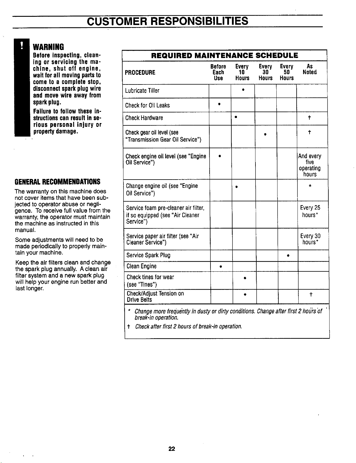
REQUIRED MAINTENANCE SCHEDULE
PROCEDURE
Before Every Every Every As
Each 10 30 50 Noted
Use Hours Hours Hours
LubricateTiller
Checkfor 0il Leaks
CheckHardware
Checkgearoil level(see
"Transmission Gear0il Service")
t
t
Checkengineoillevel(see"Engine
Oil Service")
And every
five
operating
hours
Changeengine oil (see"Engine
0il Service")
Servicefoampre-cleanerair filter,
if so equipped (see"Air Cleaner
Service")
Every25
hours*
Servicepaperairfilter(see"Air
CleanerService")
Every3O
hours*
ServiceSpark Plug
CleanEngine •
Checktines for wear °
(see"Tines")
Check/AdjustTension on •
DriveBelts
t
* Changemore freque'ntlyin dusty or dirty conditions. Changeafter first 2 ho_'rs"of
break-in operation.
t Checkafterfirst2 hours of break-in operation.
22
CUSTOMER RESPONSIBILITIES
B ARNING Beforeinspecting,cleaningor servicingthe unit, shut off engine, wait for all tl......
partsto cometo a completestop, disconnectspark plugwire and movewire away from spark
plug. Failure to follow these instructions can result in serious personal injury or
propertydamage. ,
RegularMaintenance CheckForOilLeaks
Because the tiller is operated in the
garden, frequently under hot and
dirty conditions, regular maintenance
is very important to ensure that you
are getting proper performance from
your tiller. There are several mainte-
nance procedures that will help keep
your tiller in good operating condition.
•oChange engine oil regularly.
• Lubricatethe controls regularly.
• Keep the correct tension on the for-
ward drive belt.
• Replace the engine air cleaner ele-
ment when dirty.
• Keep engine cooling fins clean.
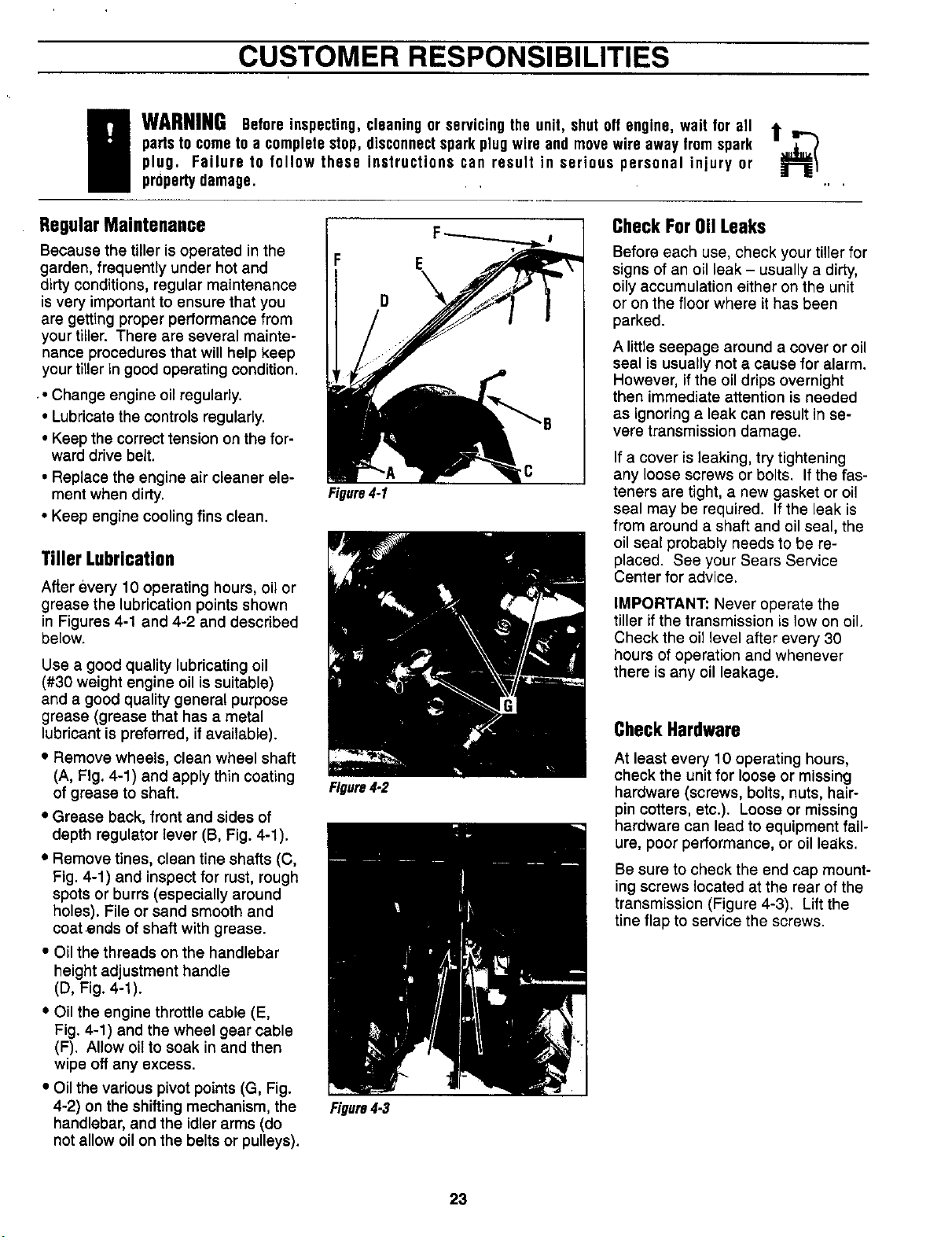
Tiller Lubrication
After every 10 operating hours, oil or
grease the lubrication points shown
in Figures 4-1 and 4-2 and described
below.
Use a good quality lubricating oil
(#30 weight engine oil is suitable)
and a good quality general purpose
grease (grease that has a metal
lubricant is preferred, if available).
• Remove wheels, clean wheel shaft
(A, Fig. 4-1) and apply thin coating
of grease to shaft.
• Grease back, front and sides of
depth regulator lever (B, Fig. 4-1).
• Remove tines, clean tine shafts (C,
Fig. 4-1) and inspect for rust, rough
spots or burrs (especially around
holes). File or sand smooth and
coat ends of shaft with grease.
• Oil the threads on the handlebar
height adjustment handle
(D, Fig. 4-1).
• Oil the engine throttle cable (E,
Fig. 4-1) and the wheel gear cable
(F). Allow oil to soak in and then
wipe off any excess.
• Oil the various pivot points (G, Fig.
4-2) on the shiftingmechanism, the
handlebar, and the idler arms (do
not allow oil on the belts or pulleys).
F
D
Figure4-1
Figure4.2
Figure4-3
E
Before each use, check your tiller for
signs of an oil leak - usually a dirty,
oily accumulation either on the unit
or on the floor where it has been
parked.
A little seepage around a cover or oil
seal is usually not a cause for alarm.
However, if the oil drips overnight
then immediate attention is needed
as ignoring a leak can result in se-
vere transmission damage.
If a cover isleaking, try tightening
any loose screws or bolts. If the fas-
teners are tight, a new gasket or oil
seal may be required. If the leak is
from around a shaft and oil seal, the
oil seal probably needs to be re-
placed. See your Sears Service
Center for advice.
IMPORTANT: Never operate the
tiller if the transmission is low on oil.
Check the oil level after every 30
hours of operation and whenever
there isany oil leakage.
CheckHardware
At least every 10 operating hours,
check the unit for loose or missing
hardware (screws, bolts, nuts, hair-
pin cotters, etc.). Loose or missing
hardware can lead to equipment fail-
ure, poor performance, or oil leaks.
Be sure to check the end cap mount-
ing screws located at the rear ofthe
transmission (Figure 4-3). Lift the
tine flap to service the screws.
23
CUSTOMER RESPONSIBILITIES
B ARNINGBeforeinspecting,cleaningor servicingthe unit, shut off engine, wait for all t ,,.-._
partsto cometo a completestop, disconnectspark plugwire and movewire away from spark
plug. Failure to follow these instructions can result in serious personal injury or ,
propertydamage,
Transmission Gear 0il Service gear oil reaches the rear (tine) end ToChangethe Engine0il
of the transmission. Stop adding Only use high quality detergent oil
gear oil when it begins to flow from with an A.P.I. rating of service ciassi-
the oil level check hole on the side of fication "SF", "SG", "SH" or "SH/CD."
the transmission. Select the oil SAE viscosity grade
according to your expected operat-
ing temperature:
Check the transmission gear oil level
every 30 hours of operation or when
you notice any oil leak. Operating
the tiller when the transmission is
low on.0il .can cause severe damage.
ToCheckTransmissionGearOil Level
1. Check the gear oil level when the
transmission is cool. Gear oil will ex-
pand in warm operating tempera-
tures and this expansion will provide
an incorrect oil level reading.
2. To check the gear oil level (and to
add oil, if needed), see "STEP 4:
Check Gear Oil Level in Transmis-
sion" in the Assembly Section of this
manual.
ToDrain and Refill theTransmission
The transmission gear oil does not
need to be changed unless contami-
nated with dirt, sand or metal bits.
1. Prop up the left side of the unit so
that it will be securely supported
when the left side wheel is removed.
Remove the left side wheel by re-
moving the wheel pin.
2. Unscrew the gear oil fill plug from
the top of the transmission.
3. Place a clean pan below the
transmission drain plug (see Figure
4-4) and remove the drain plug. The
oil will start flowing out of the drain
hole (it may flow slowly, especially in
cold temperatures).
4. Remove the transmission gear oil
level check plug located a few inch-
es above the left side wheel shaft.
5. When the oil stops flowing, tilt the
transmission forward to drain oil from
the rear of the transmission.
6. After draining the oil, clean the
threads of the drain plug, apply a
non-hardening, removable gasket
sealant to the threads, and securely
reinstall the drain plug.
7. U_ihg a clean funnel, slowly add
SAE 140 or SAE 85W-140 weight
gear oil (with an API rating of GL-4
only) to the transmission. The trans-
mission holds approximately 3-1/4
pints (52-54 ounces). Tilt the tiller
slightly backwards to make sure the
8. Securely reinstall the check plug.
9. Securely reinstall the gear oil fill
plug on top of the transmission.
10. Reinstall the wheel and remove
the prop.
Figure4-4: Removedrainplugtodrain
transmissiongearoff(alsoremoveofffill
plugandoillevelcheckplug).
EngineOilService
Check the engine oil level before
starting the engine each day and
check it after 5 hours of continuous
operation. Running the engine when
low on oil will quickly ruin the engine.
It is recommended that you change
motor oil after every 10 hours of op-
eration (sooner when operating in
extremely dirty or dusty conditions.)
ToCheckthe Engine0il Level
1. Move the tiller to a level area and
shut off the engine.
2. Level the engine by puttingthe
Depth Regulator Lever in the second
notch from the top.
3. Clean the area around the oil dip-
stick or oil filltube to prevent dirt
from falling into the crankcase.
4. Remove the oil dipstick from the
oil fill tube, wipe the diihstick clean,
and reinstall it finger-tight. Remove
the dipstick and check the reading.
Add oil (if required) to bring the level
to the FULL mark. Do not overfill.
24
colder-.<.----.-- 32OF..--_ • warmer
5W30 SAE 30
NOTE: Although multi-viscosity oils
(5W30, 10W30, etc. improve starting
in cold weather, these multi-viscosity
oils will result in increased consump-
tion when used above 32°1::. Check
your engine oil level more frequently
to avoid possible engine damage
from running low on oil. DO NOT
USE 10W40 OIL.
1. Start engine and let it warm up.
Then TURN THE ENGINE OFF.
2. There is an oil drain plug on each
side of the engine base. Use
whichever one is most convenient.
3. Place a 2"x4" wood board under
the wheel opposite the drain plug
you'll be removing.
4. Place a drain pan beneath the
drain plug.
5. Remove the drain plug (Figure
4-5), and allow the old oil to drain
completely.
e. Reinstall drain plug securely.
7. Remove wood board from be-
neath the wheel.
8. Remove the dipstick from the oil
fill tube (see Figure 4-5). Using a
funnel in the tube, refill the engine
with the correct type and weight en-
gine oil. Check the level frequently
while filling so as not to overfill. Fill
until oil is at the FULL mark on the
dipstick. Install the dipstick.
Figure4-5
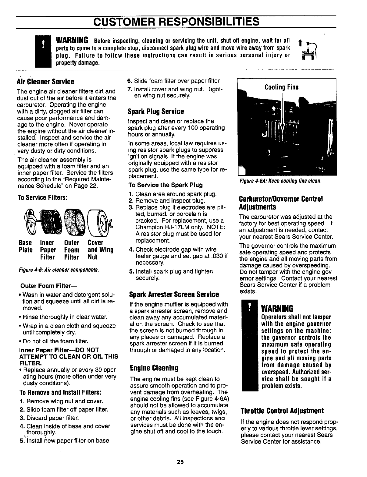
CUSTOMER RESPONSIBILITIES
g ARNINGBeforeinspecting,cleaningor servicingthe unit, shut off engine, wait for all t ,,-..
partsto cometo a completestop, disconnectspark plugwire and movewire away from spark
plug. Failure to follow these instructions can result in serious personal injury or
propertydamage.
A'irCleanerService
The engine air cleaner filters dirt and
dust out of the air before it enters the
carburetor. Operating the engine
with a dirty, clogged air filter can
cause poor performance and dam-
age to the engine. Never operate
the engine without the air cleaner in-
stalled. Inspect and service the air
cleaner more often if operating in
•very dusty or dirty conditions.
The air cleaner assembly is
equipped with a foam filter and an
inner paper filter. Service the filters
according to the "Required Mainte-
nance Schedule" on Page 22.
ToServiceFilters:
Base Inner Outer Cover
Plate Paper Foam andWing
Filter Filter Nut
Figure4-6:Aircleanercomponents.
Outer Foam Filter--
• Wash in water and detergent solu-
tion and squeeze until all dirt is re-
moved.
• Rinse thoroughly in clear water.
• Wrap in a clean cloth and squeeze
until 'completely dry.
• Do not oil the foam filter.
Inner Paper Filter--DO NOT
ATTEMPT TO CLEAN OR OIL THIS
FILTER.
• Replace annually or every 30 oper-
ating hours (more often under very
dusty conditions).
To Remove and Install Filters:
1. Remove wing nut and cover.
2. Slide foam filter off paper filter.
3. Discard paper filter.
4. Clean inside of base and cover
thoroughly.
5. Install new paper filter on base.
e. Slide foam filter over paper filter.
7. Install cover and wing nut. Tight-
en wing nut securely.
SparkPlugService
Inspect and clean or replace the
spark plug after every 100 operating
hours or annually.
In some areas, local law requires us-
ing resistor spark plugs to suppress
ignition signals• If the engine was
originally equipped with a resistor
spark plug, use the same type for re-
placement.
To Service the Spark Plug
1. Clean area around spark plug.
2. Remove and inspect plug.
3. Replace plug if electrodes are pit-
ted, burned, or porcelain is
cracked. For replacement, use a
Champion RJ-17LM only. NOTE:
A resistor plug must be used for
replacement.
4. Check electrode gap with wire
feeler gauge and set gap at .030 if
necessary.
5. Install spark plug and tighten
securely.
SparkArresterScreenService
If the engine muffler is equipped with
a spark arrester screen, remove and
clean away any accumulated materi-
al on the screen. Check to see that
the screen is not burned through in
any places or damaged. Replace a
spark arrester screen if it is burned
through or damaged in any location.
EngineCleaning
The engine must be kept clean to
assure smooth operation and to pre-
vent damage from overheating. The
engine cooling fins (see Figure 4-6A)
should not be allowed to accumulate
any materials such as leaves, twigs,
or other debris. All inspections and
services must be done with the en-
gine shut off and cool to the touch•
CoolingFins
Figure4.6A:Keepcoolingfinsclean.
Carburetor/GovernorControl
Adjustments
The carburetor was adjusted at the
factory for best operating speed, if
an adjustment is needed, contact
your nearest Sears Service Center.
The governor controls the maximum
safe operating speed and protects
the engine and all moving parts from
damage caused by overspeeding.
Do not tamper with the engine gov-
ernor settings. Contact your nearest
Sears Service Center if a problem
exists.
WARNING
Operators shall not tamper
with the engine governor
settings on the machine;
the governor controls the
maximum safe operating
speed to protect the en-
gine and all moving parts
from damage caused by
overspeed. Authorizedser-
vice shall be sought if a
problem exists.
ThrottleControlAdjustment
If the engine does not respond prop-
erly to various throttle lever settings,
please contact your nearest Sears
Service Center for assistance.
25
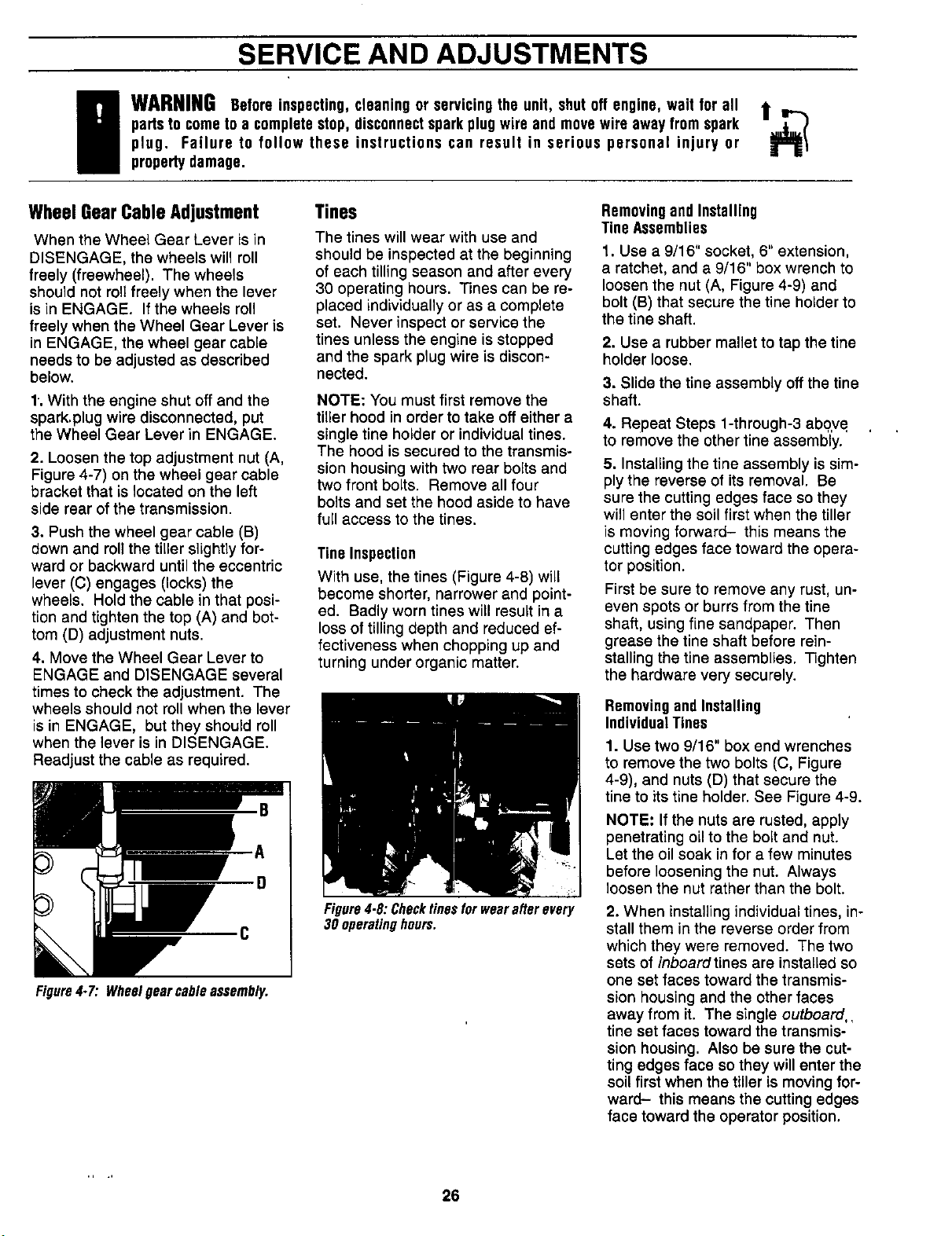
SERVICE AND ADJUSTMENTS
E ARNINGBefore inspecting,cleaning or servicingthe unit, shut off engine, wait for all t ..--.
partsto cometo a completestop, disconnectsparkplugwire and movewire awayfrom spark
plug. Failure to fallow these instructions can result in serious personal injury or
propertydamage.
WheelGearGableAdjustment Tines RemovingandInstalling
TineAssemblies
When the Wheel Gear Lever is in
DISENGAGE, the wheels will roll
freely (freewheel). The wheels
should not roll freely when the lever
is in ENGAGE. If the wheels roll
freely when the Wheel Gear Lever is
in ENGAGE, the wheel gear cable
needs to be adjusted as described
below.
1, With the engine shut off and the
spark.plug wire disconnected, put
the Wheel Gear Lever in ENGAGE.
2. Loosen the top adjustment nut (A,
Figure 4-7) on the wheel gear cable
bracket that is located on the left
side rear of the transmission.
3. Push the wheel gear cable (B)
down and roll the tiller slightly for-
ward or backward until the eccentric
lever (C) engages (locks) the
wheels. Hold the cable in that posi-
tion and tighten the top (A) and bot-
tom (D) adjustment nuts.
4. Move the Wheel Gear Lever to
ENGAGE and DISENGAGE several
times to check the adjustment. The
wheels should not roll when the lever
is in ENGAGE, but they should roll
when the lever is in DISENGAGE.
Readjust the cable as required.
Figure4.7: Wheelgearcableassembly,
The tines will wear with use and
should be inspected at the beginning
of each tilling season and after every
30 operating hours. Tines can be re-
placed individually or as a complete
set. Never inspect or service the
tines unless the engine is stopped
and the spark plug wire is discon-
nected.
NOTE: You must first remove the
tiller hood in order to take offeither a
single tine holder or individual tines.
The hood is secured to the transmis-
sion housing with two rear bolts and
two front bolts. Remove all four
bolts and set the hood aside to have
full access to the tines.
Tine Inspection
With use, the tines (Figure 4-8) will
become shorter, narrower and point-
ed. Badly worn tines will result in a
loss of tilling depth and reduced ef-
fectiveness when chopping up and
turning under organic matter.
Figure4-8:Checktinesforwearafterevery
30 operatinghours.
1. Use a 9/16" socket, 6" extension,
a ratchet, and a 9/16" box wrench to
loosen the nut (A, Figure 4-9) and
bolt (B) that secure the tine holder to
the tine shaft.
2. Use a rubber mallet to tap the tine
holder loose.
3. Slide the tine assembly offthe tine
shaft.
4. RePeat Steps 1-through-3 abo..ve
to remove the other tine assembly.
5. Installing the tine assembly is sim-
ply the reverse of its removal. Be
sure the cutting edges face so they
will enter the soil first when the tiller
is moving forward- this means the
cutting edges face toward the opera-
tor position.
First be sure to remove any rust, un-
even spots or burrs from the tine
shaft, using fine sandpaper. Then
grease the tine shaft before rein-
stalling the tine assemblies. Tighten
the hardware very securely.
Removingand Installing
IndividualTines
1. Use two 9/16" box end wrenches
to remove the two bolts (C, Figure
4-9), and nuts (D) that secure the
tine to its tine holder. See Figure 4-9.
NOTE: If the nuts are rusted, apply
penetrating oil to the bolt and nut.
Let the oil soak in for a few minutes
before loosening the nut. Always
loosen the nut rather than the bolt.
2. When installing individual tines, in-
stall them in the reverse order from
which they were removed. The two
sets of inboard tines are installed so
one set faces toward the transmis-
sion housing and the other faces
away from it. The single outboard,.
tine set faces toward the transmis-
sion housing. Also be sure the cut-
ting edges face so they will enter the
soil first when the tiller is moving for-
ward- this means the cutting edges
face toward the operator position.
26
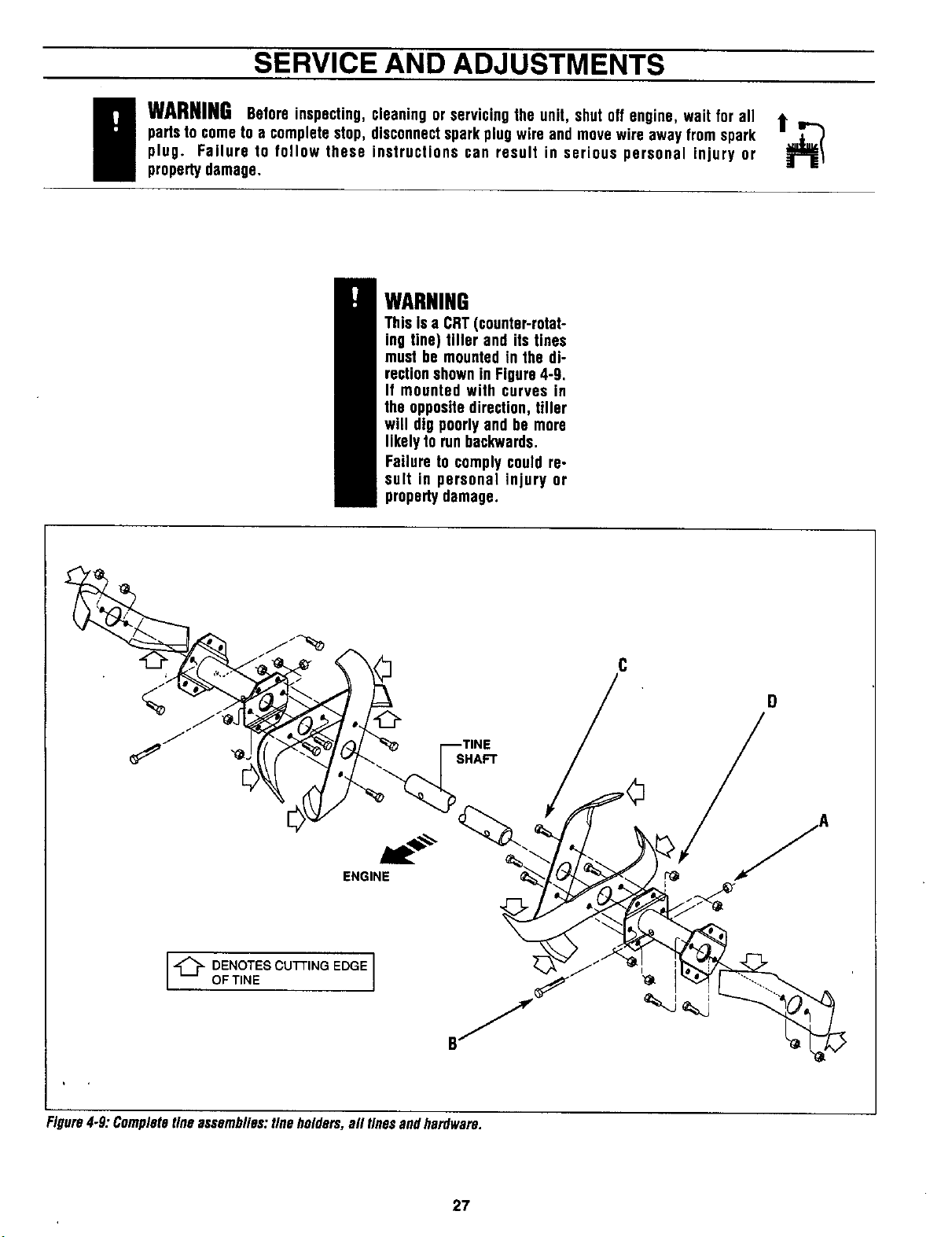
SERVICE AND ADJUSTMENTS
i ARNINGBeforeinspecting,cleaning or servicingthe unit, shut off engine, wait for all t_
partsto cometo a completestop, disconnectsparkplug wire and movewire away fromspark
plug. Failure to follow these instructions can result in serious personal injury or
propertydamage.
WARNING
Thisis a CRT(counter-rotat-
ing tine) tiller and its tines
must be mountedin the di-
rectionshownin Figure4-9.
It mounted with curves in
the oppositedirection,tiller
will dlg poorlyend be more
likelyto runbackwards.
Failure to complycould re-
sult in personal injury or
propertydamage.
A
Figure4-9: Completetineassemblies:fineholders,all tinesandhardware.
27
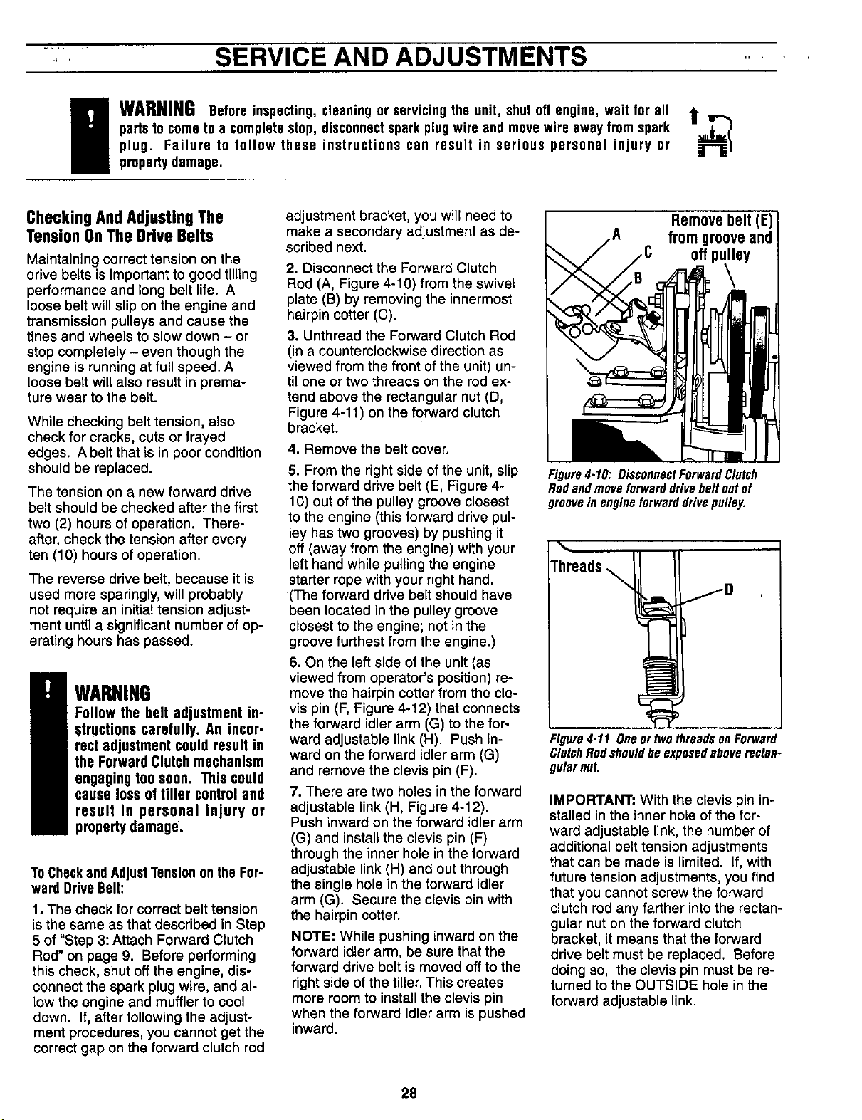
....;, SERVICE AND ADJUSTMENTS .....
g ARNINGBefore inspecting,cleaningor servicingthe unit, shut off engine, wait for all t ,,,.-..
partsto cometo a completestop, disconnectsparkplug wire and movewire away fromspark
plug. Failure to follow these instructions can result in serious personal injury or
propertydamage.
CheckingAndAdjustingThe
TensionOnThe DriveBelts
Maintaining correct tension on the
drive betts is important to good tilling
performance and long belt life. A
loose belt will slip on the engine and
transmission pulleys and cause the
tines and wheels to slow down - or
stop completely - even though the
engine is running at full speed. A
loose belt wilt also result in prema-
ture wear to the belt.
While checking belt tension, atso
check for cracks, cuts or frayed
edges. A belt that is in poor condition
should be replaced.
The tension on a new forward drive
belt should be checked after the first
two (2) hours of operation. There-
after, check the tension after every
ten (10) hours of operation.
The reverse drive belt, because it is
used more sparingly, will probably
not require an initial tension adjust-
ment until a significant number of op-
erating hours has passed.
WARNING
Follow the belt adjustment in-
structions carefully.An incor-
rect adjustment could result in
the ForwardClutch mechanism
engaging too soon. This could
cause loss of tiller controland
result in personal injury or
propertydamage.
ToCheckandAdjustTensiononthe For-
ward DriveBelt:
1. The check for correct belt tension
is the same as that described in Step
5 of "Step 3: Attach Forward Clutch
Rod" on page 9. Before performing
this check, shut off the engine, dis-
connect the spark plug wire, and al-
low the engine and muffler to cool
down. If, after following the adjust-
ment procedures, you cannot get the
correct gap on the forward clutch rod
adjustment bracket, you will need to
make a secondary adjustment as de-
scribed next.
2. Disconnect the Forward Clutch
Rod (A, Figure 4-10) from the swivel
plate (B) by removing the innermost
hairpin cotter (C).
3. Unthread the Forward Clutch Rod
(in a counterclockwise direction as
viewed from the front of the unit) un-
til one or two threads on the rod ex-
tend above the rectangular nut (D,
Figure 4-11) on the forward clutch
bracket.
4. Remove the belt cover.
5. From the right side of the unit, slip
the forward drive belt (E, Figure 4-
10) out of the pulley groove closest
to the engine (this forward drive pul-
ley has two grooves) by pushing it
off (away from the engine) with your
left hand while pulling the engine
starter rope with your right hand.
(The forward drive belt should have
been located in the pulley groove
closest to the engine; not in the
groove furthest from the engine.)
6. On the left side of the unit (as
viewed from operator's position) re-
move the hairpin cotter from the cle-
vis pin (F, Figure 4-12) that connects
the forward idler arm (G) to the for-
ward adjustable link (H). Push in-
ward on the forward idler arm (G)
and remove the clevis pin (F).
7. There are two holes in the forward
adjustable link (H, Figure 4-12).
Push inward on the forward idler arm
(G) and installthe clevis pin (F)
through the inner hole in the forward
adjustable link(H) and out through
the single hole in the forward idler
arm (G). Secure the clevis pin with
the hairpin cotter.
NOTE: While pushing inward on the
forward idler arm, be sure that the
forward drive belt is moved off to the
right side of the tiller. This creates
more room to install the clevis pin
when the forward idler arm is pushed
inward.
Removebelt (E)]
fromgrooveandt
offpt
Figure4-10: DisconnectForwardClutch
Rodandmoveforwarddrivebeltoutof
grooveinengineforwarddrivepulley.
Figure4.11 Oneor_vothreadsonForward
ClutchRodshouldbeexposedaboverectan-
gularnut.
IMPORTANT: With the clevis pin in-
stalled in the inner hole of the for-
ward adjustable link, the number of
additional belt tension adjustments
that can be made is limited. If, with
future tension adjustments, you find
that you cannot screw the forward
clutch rod any farther into the rectan-
gular nut on the forward clutch
bracket, it means that the forward
drive belt must be replaced. Before
doing so, the clevis pin must be re-
turned to the OUTSIDE hole in the
forward adjustable link.
28

SERVICE AND ADJUSTMENTS
WARNINGBeforeinspecting,cleaning or servicingthe unit, shutoff engine,wait for all t =--.,
partsto cometo a completestop,disconnectsparkplugwire and movewire away fromspark
plug. Failure to follow these instructions can result in serious personal injury or
propertydamage.
8. Replace the forward drive belt in
the High speed groove of the engine
drive pulley (the groove closest to
the engine) and in the middle groove
i_ the tr_.nsmission pulley. Be sure
the belt is to the insideof the wire
formed belt guide (I, Figure 4-13) and
to the inside of the forward drive idler
pulley (J).
9. Reinstall the belt cover and se-
cure it with the two nuts.
10. Readjust the forward drive belt
tension by following the instructions
'in,'item' 5 of "Step 3: Attach Forward
Clutch Rod" on Page 9.
Figure4.12: Removeclevispinfromouter
holeinforwardadjustablelinkandmoveto
innerholeinlink.
• The belt tension is correct if the
guide mark (M, Figure 4-15) is any-
where to the left of the guide pin
(O), as viewed from the front of the
unit (not the operator's position). If
the belt tension is correct, reinstall
the belt cover and secure it with the
two nuts.
• If the guide mark is aligned with the
guide pin, or moves to the right
side of the guide pin, then the belt
is too loose and the tension must
be readjusted as described next.
3. The reverse idler pulley (L, Figure
4-14) regulates the tension that is
applied to the reverse drive belt (P).
The following adjustment will allow
the reverse idler pulley to apply more
tension to a loose belt.
4. Remove the belt cover.
5. Slip the reverse belt (P, Figure 4-
14) off the engine driven reverse
(upper) pulley.
6. On the right side of the unit (as
viewed from operator's position) re-
move the hairpin cotter from the cle-
vis pin (R, Figure 4-14) that connects
the reverse idler arm (K) to the re-
verse adjustable link. Push inward
on the reverse idler arm (K) and re-
move the clevis pin (R).
To CheckandAdjustTensionanthe Re-
verseDriveBelt
1. Remove the belt cover after first
shutting off the engine, disconnect-
ing the spark plug wire, and allowing
the engine and muffler to cool down.
2. Stand at the front of the tiller and
use your left hand to push the re-
verse idler arm (K, Figure 4-14) in-
ward as far as possible (the reverse
idler pulley [L] is attached to the re-
verse idler arm). Hold the idler arm
in this position and look at the posi-
tion of the belt tension guide mark
(M, Figure 4-15) that is stamped into
the face of the reverse adjustable
link (N, Figure 4-15).
Figure4-13: Topviewofbeltsandpulleys.
Figure4-14 : Reverseidlerarm(K)andre.
versepulley(L).
Figure4-15:Whilepushingreverseidlerarm
Inward,standatengineendandcheckposi.
t/onofguidemark(#7)andguidepin(0).
29
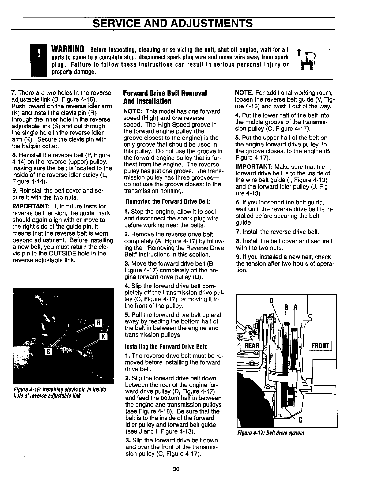
SERVICE AND ADJUSTMENTS
g WARNINGBeforeinspecting,cleaningor servicingthe unit, shut off engine, wait for all it--.
partsto cometo a completestop, disconnectspark plugwire and movewire away from spark
plug. Failure to follow these instructions can result in serious personal injury or
propertydamage.
7. There are two holes in the reverse
adjustable link (S, Figure 4-16).
Push inward on the reverse idler arm
(K) and install the clevis pin (R)
through the inner hole in the reverse
adjustable link (S) and out through
the single hole in the reverse idler
arm (K). Secure the clevis pin with
the hairpin cotter.
8. Reinstall the reverse belt (P, Figure
4-14) on the reverse (upper) pulley,
making sure the belt is located to the
inside of the reverse idler pulley (L,
Figure 4-14).
9. Reinstall the belt cover and se-
cure it with the two nuts.
IMPORTANT: If, in future tests for
reverse belt tension, the guide mark
should again align with or move to
the right side of the guide pin, it
means that the reverse belt is worn
beyond adjustment. Before installing
a new belt, you must return the cle-
vis pin to the OUTSIDE hole in the
reverse adjustable link.
Figure4-16:InstallingclevispinInInside
holeofreverseadjustablelink.
ForwardDriveBelt Removal
AndInstallation
NOTE: This model has one forward
speed (High) and one reverse
speed. The High Speed groove in
the forward engine pulley (the
groove closest to the engine) is the
only groove that should be used in
this pulley. Do not use the groove in
the forward engine pulley that isfur-
thest from the engine. The reverse
pulley hasjustone groove. The trans-
mission pulley has three grooves--
do not use the groove closest to the
transmission housing.
Removingthe ForwardDriveBelt:
1. Stop the engine, allow it to cool
and disconnect the spark plug wire
before working near the belts.
2. Remove the reverse drive belt
completely (A, Figure 4-17) by follow-
ing the "Removing the Reverse Drive
Belt" instructions in this section.
3. Move the forward drive belt (B,
Figure 4-17) completely off the en-
gine forward drive pulley (D).
4. Slip the forward drive belt com-
pletely off the transmission drive pul-
ley (C, Figure 4-17) by moving it to
the front of the pulley.
5. Pull the forward drive belt up and
away by feeding the bottom half of
the belt in between the engine and
transmission pulleys.
Installingthe ForwardDriveBelt:
1. The reverse drive belt must be re-
moved before installing the forward
drive belt.
2. Slip the forward drive belt down
between the rear of the engine for-
ward drive pulley (D, Figure 4-17)
and feed the bottom half in between
the engine and transmission pulleys
(see Figure 4-18). Be sure that the
belt is to the inside of the forward
idler pulley and forward belt guide
(see J and I, Figure 4-13).
3. Slip the forward drive belt down
and over the front of the transmis-
sion pulley (C, Figure 4-17).
NOTE: For additional working room,
loosen the reverse belt guide (V, Fig-
ure 4-13) and twist it out of the way.
4. Put the lower half of the belt into
the middle groove of the transmis-
sion pulley (C, Figure 4-17).
5. Put the upper half of the belt on
the engine forward drive pulley in
the groove closest to the engine (B,
Figure 4-17).
IMPORTANT: Make sure that the ,.
forward drive belt isto the inside of
the wire belt guide (I, Figure 4-13)
and the forward idler pulley (J, Fig-
ure 4-13).
6. If you loosened the belt guide,
wait until the reverse drive belt is in-
stalled before securing the belt
guide.
7. Install the reverse drive belt.
8. Install the belt cover and secure it
with the two nuts.
9. If you installed a new belt, check
the tension after two hours of opera-
tion.
D
BA
C
Figure4-17:Beltdrivesystem.
3O
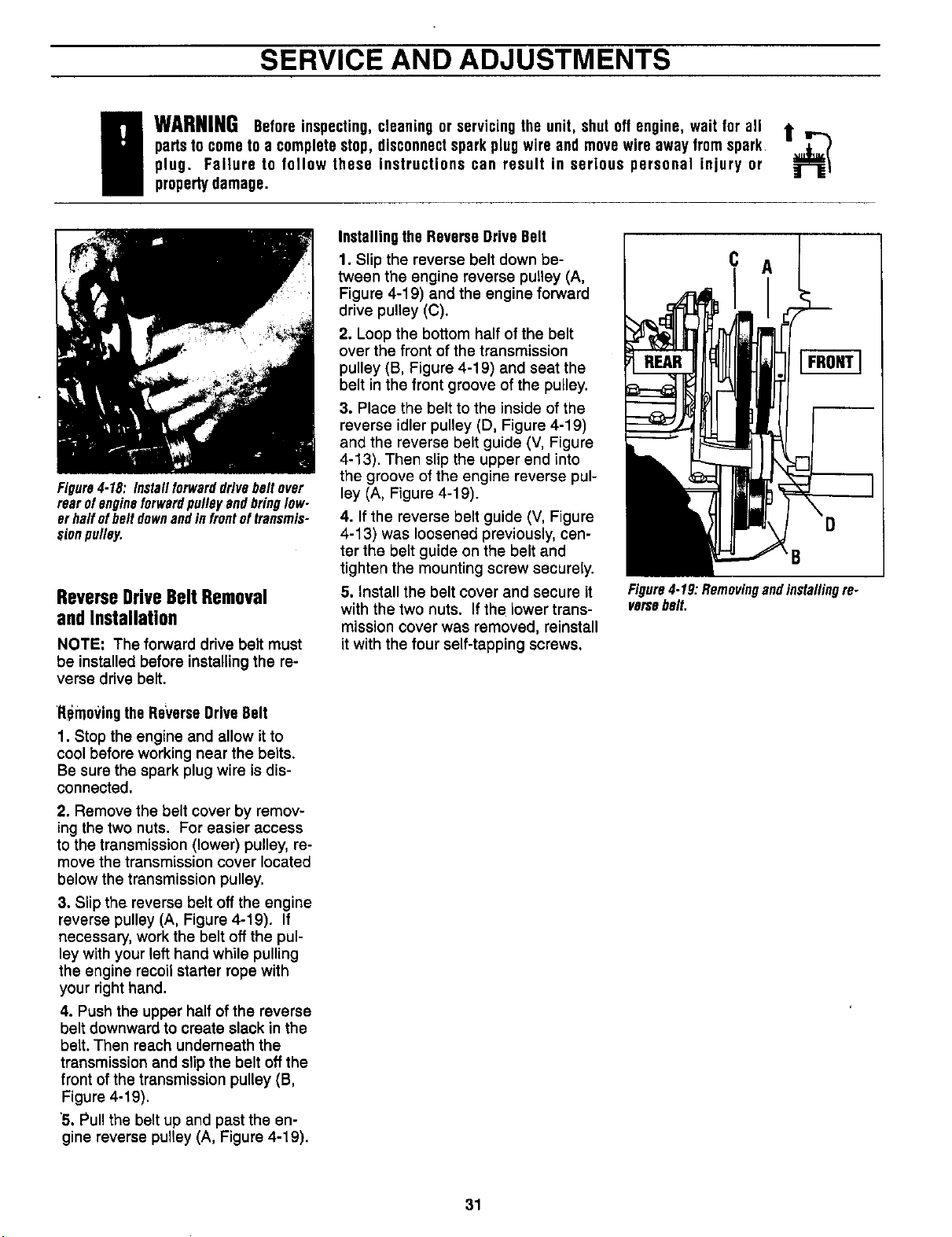
SERVICE AND ADJUSTMENTS
g ARNINGBeforeinspecting,cleaning or servicingthe unit, shut off engine, wait for all t ,,.....
partsto cometo a completestop, disconnectspark plugwire and movewire away from spark
plug. Failure to follow these instructions can result in serious personal injury or
propertydamage.
Figure4.18: Installforwarddrivebeltover
rearofengineforwardpulleyandbringlow-
erhalfofbelldownandinfrontoftransmis-
sionpulley.
Reverse Drive Belt Removal
and Installation
NOTE: Theforward drivebeltmust
be installedbeforeinstallingthe re-
versedrivebelt.
'RemovingtheRe_'erseDriveBelt
1. Stop the engine and allow it to
cool before working near the belts.
Be sure the spark plug wire is dis-
connected.
2. Remove the belt cover by remov-
ing the two nuts. For easier access
to the transmission (lower) pulley, re-
move the transmission cover located
below the transmission pulley.
3. Slip the reverse belt off the engine
reverse pulley (A, Figure 4-19). If
necessary, work the belt off the pul-
ley with your left hand while pulling
the engine recoil starter rope with
your right hand.
4. Push the upper half of the reverse
belt downward to create slack in the
belt. Then reach underneath the
transmission and slip the belt off the
front of the transmission pulley (B,
Figure 4-19).
'5. Pull the belt up and past the en-
gine reverse pulley (A, Figure 4-19).
Installingthe ReverseDriveBelt
1. Slip the reverse belt down be-
tween the engine reverse pulley (A,
Figure 4-19) and the engine forward
drive pulley (C).
2. Loop the bottom half of the belt
over the front of the transmission
pulley (B, Figure 4-19) and seat the
belt in the front groove of the pulley.
3. Place the belt to the inside of the
reverse idler pulley (D, Figure 4-19)
and the reverse belt guide (V, Figure
4-13). Then slip the upper end into
the groove of the engine reverse pul-
ley (A, Figure 4-19).
4. If the reverse belt guide (V, Figure
4-13) was loosened previously, cen-
ter the belt guide on the belt and
tighten the mounting screw securely.
5. Install the belt cover and secure it
with the two nuts. If the lower trans-
mission cover was removed, reinstall
it with the four self-tapping screws,
B
Figure4-19:Removingandinstallingre.
versabelt.
31
STORAGE
TiBerStorage
Whenever you don't intend to use
your tiller for 30 days or longer, you
should perform the following steps to
ensure that it will start easily and
perform properly when removed
from storage.
• Thoroughly clean the machine.
• Be sure that all nuts, bolts and
screws are securely fastened. In-
spect parts for damage, breakage
or wear. Replace as necessary.
• Touch up all rusted or chipped
• paint surfaces. Sand lightly before
repainting.
• If possible, store your unit indoors
and cover it with a suitable protec-
tive oover (not plastic) that does
not retain moisture.
IMPORTANT: Never cover the unit
while the engine and exhaust areas
are still warm.
• Do not store gasoline from one
season to another.
• Replace your gasoline can if it
starts to rust. Rust and/or dirt in
your gasoline will cause problems.
EngineStorage
FuelSystem
IMPORTANT: It is important to pre-
vent gum deposits from forming in
essential fuel system parts such as
carburetor, fuel filter, fuel hose, or
tank during storage. Also, experi-
ence indicates that alcohol blended
fuels (called gasohol or using
ethanol or methanol) can attract
moisture which leads to separation
and formation of acids during stor-
age. Acidic gas can damage the fuel
system ofan engine while in
storage.
DANGER
Gasolineishighlyflammableanditsvaporsareexplosive.Followthesesafety
practicestopreventinjuryorpropertydamagefromfireorexplosion.
• Let engineandmufflercoolat least2 minutesbeforedrainingfueltank.
• Do notallow openflames, sparks,or matches,or permitsmokingin fuel-
ingarea.
• Wipe upspills and pushthetiller awayfromspilled fuel.
• Useonlyan approvedfuel containerandstoreit safelyfromchildren.
• Do not store gasoline in an area where its vaporscould reach an open
flame or spark, or where ignitionsourcesare near (suchas hotwater and
spaceheaters,furnaces,clothesdryers,stoves,motors,etc.)
• Drain the fuel tank.
• Start the engine and let it run until
the fuel lines and carburetor are
empty.
• Never use engine or carburetor
cleaner products in the fuel tank or
permanent damage may occur.
• Use fresh fuel next season.
NOTE: If "Gasohol" has been used,
run engine until the tank is empty.
Then put 1/2 pint of "Unleaded" reg-
ular gasoline into the fuel tank and
again run the engine until tank is
empty.
NOTE: Fuel stabilizer (such as
Craftsman Fuel Stabilizer No.
33550) is an acceptable alternative
in minimizing the formation of fuel
gum deposits during storage. Add
stabilizer to gasoline in fuel tank or
storage container. Always fo]low the
mix ratio and instructions on the sta-
bilizer container. Run engine at least
10 minutes after adding stabilizer to
allow the stabilizer to reach the car-
buretor. Do not drain the gas tank
and carburetor if using fuel stabilizer
EngineOil
Drain oil and replace with clean en-
gine oil. See "Engine Lubrication" in
the CUSTOMER RESPONSIBILI-
TIES section.
EngineCylinder
• Remove spark plug. Squirt one (1)
oz. (30ml) of clean engine oil into
spark plug hole.
• Cover spark plug hole with a clean
rag.
• Pull starter rope to crank engine
over, slowly, several times.
• Install spark plug. Do not connect
spark plug wire.
32
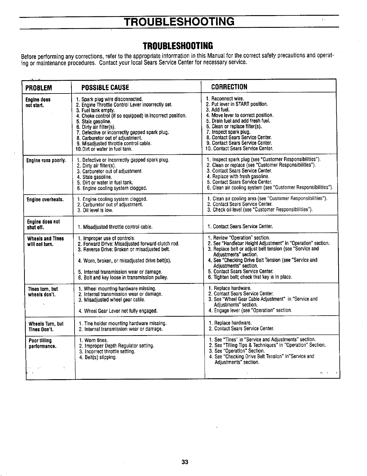
TROUBLESHOOTING
TROUBLESHOOTING
Beforeperforming anycorrections, referto the appropriate information in this Manualfor the correct safety precautionsand operat-
ing or maintenanceprocedures. Contactyour local SearsServiceCenterfor necessaryservice.
PROBLEM
Enginedoes
notstart,
Enginerunspoorly.
Engineoverheats,
Enginedoesnot
shutoff.
WheelsandTines
willnotturn.
Tinesturn,but
wheelsdon't.
WheelsTurn,but
TinesDon't.
Poortilling
partormance.
POSSIBLECAUSE
1. Sparkplugwiredisconnected.
2. EngineThrottLeControlLeverincorrectlyset.
3. Fueltankempty.
4. Chokecontrol(if so equipped)in incorrect position.
5. Stalegasoline.
6. Dirtyairfilter(s).
7. Detectiveorincorrectlygappedsparkplug.
8. Carburetorout of adjustment.
9. Misadjustedthrottle controlcable.
10.Dirtor waterinfuel tank.
1. Defectiveor incorrectlygappedsparkplug.
2. Dirtyairfilter(s).
3, Carburetorout ofadjustment.
4. Stalegasoline.
5. Dirtor waterin fueltank,
6. Enginecoolingsystemclogged.
1. Enginecoolingsystemclogged.
2, CarburetorOutof adjustment.
3. Oillevelis low.
1. Misadjustedthrottle controlcable.
1. Improper useofcontrols.
2. ForwardDrive:Misadjustadforwardclutchrod.
3. ReverseDrive:Brokenor misadjustedbelt.
4.Worn,broken,ormisadjusteddrivebelt(s).
5.Internaltransmissionwearordamage.
6.Boltandkeylooseintransmissionpulley.
1. Wheelmountinghardwaremissing.
2. Internaltransmissionwear or damage.
3. Misadjustedwheelgearcable.
4. WheelGearLevernot fully engaged.
t. Tineholdermounting hardwaremissing,
2. Internaltransmissionwearor damage.
1.Worntines,
2. improperDepthRegulatorse_ing.
3. Lncorrectthrottlese_ino.
4. Belt(s)slipping.
CORRECTION
1. Reconnectwire.
2. PutleverinSTARTposition.
3. Addfuel.
4, Moveleverto correctposition.
i. Drainfuelandaddfreshfuel.
6. Cleanorreplacefilter(s).
7. Inspectsparkplug.
8. ContactSearsServiceCenter.
9. ContactSearsServiceCenter.
10, ContactSearsServiceCenter.
1. Inspectsparkplug (see"CustomerResponsibilities").
2. Cleanor replace(see"CustomerResponsibilities").
3. ContactSearsServiceCenter.
4. Replacewith fresh gasoline.
5, ContactSearsServiceCenter.
6. Cleansir coolingsystem(see"CustomerResponsibilities"),
1. Cleanaircoolingarea(see"CustomerResponsibilities").
2. ContactSearsServiceCenter.
3. Checkoil level(see"CustomerResponsibilities"),
1.ContactSearsServiceCenter.
1. Review"Operation"section.
2. See"HandlebarHeightAdjustment"in"Operation"section.
3. Replacebeltor adjust belttension(see"Serviceand
Adjustments"section.
4. See=CheckingDriveBeltTension(see"Serviceand
Adjustments"section.
5. ContactSearsServiceCenter.
6. Tightenholt; checkthatkeyisin place.
1. Replacehardware.
2. ContactSearsServiceCenter.
3. See"WheelGearCableAdjustment" in"Serviceand
Adjustments"section.
4. Engagelever(see"Operation"section.
1, Replacehardware.
2. ContactSearsServiceCenter.
1.See"Tines"in "ServiceandAdjustments"section.
2. See"TillingTips &Techniques"in "Operation"Section,
3, See"Operation"Section.
4. See"CheckingDriveBeltTension"in"Serviceand
Adjustments"section.
33
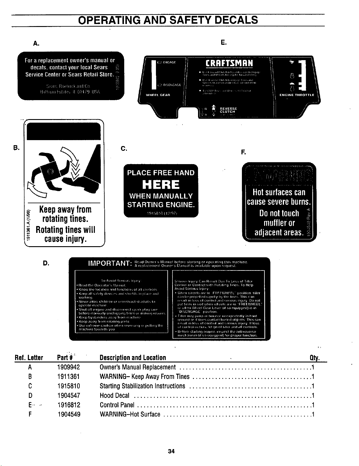
OPERATING AND SAFETY DECALS
A,
E,
B,
Keepawayfrom
rotatingtines.
Rotatingtineswill
causeinjury.
Ce
F.
D,
Ref. Le_er
A
B
C
D
E,* ,,
F
pad# _
1909942
1911361
1915810
1904547
1916612
1904549
DescriptionandLocation Qty.
Owner'sManualReplacement......................................... 1
WARNING-KeepAwayFromTines ..................................... 1
StartingStabilizationInstructions...................................... 1
HoodDecal ....................................................... 1
ControlPanel...................................................... 1
WARNING-HotSurface .............................................. 1
34
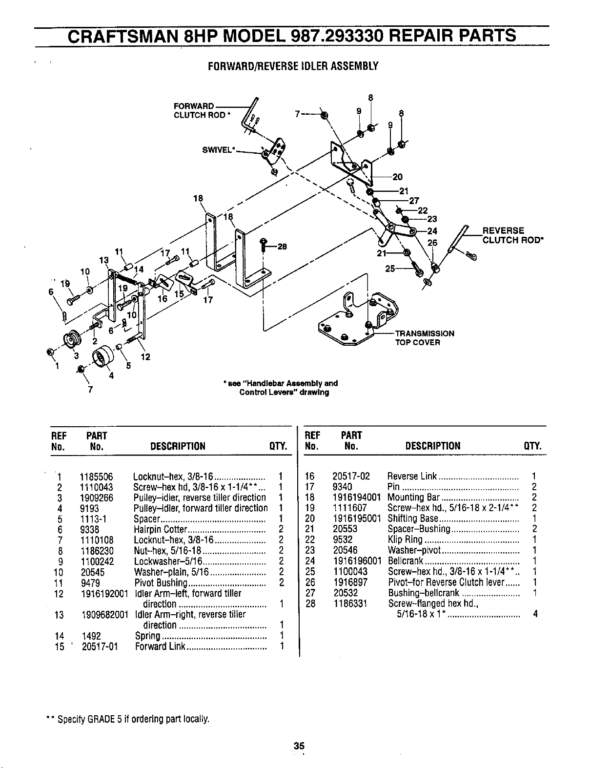
CRAFTSMAN 8HP MODEL 987.293330 REPAIR PARTS
FORWARD/REVERSEIDLERASSEMBLY
CLUTCH ROD *
8
9
lO
" 19
6
\
11
13
\
4
7
12
* see "Handlebar Assembly and
Conb'ol Levers" drawing
TOP COVER
REVERSE
CLUTCH ROD*
REF PART REF PART
No. NO. DESCRIPTION QTY. No. No. DESCRIPTION QTY.
'1 1185506
2 1110043
3 1909266
4 9193
5 1113-1
6 9338
7 1110108
8 1186230
9 1100242
10 20545
11 9479
12
13
14
15 ' 20517-01
Locknut-hex,3/8-16..................... 1
Screw-hex hd, 3/8-16 x 1-1/4"*... 1
Pulley-idler, reversetiller direction 1
Pulley-idler, forward tiller direction 1
Spacer........................................... 1
HaLrpinCotter................................ 2
Locknut-hex, 3/8-16 ..................... 2
Nut-hex, 5/16-18 .......................... 2
Lockwasher-5/16 .......................... 2
Washer-plain, 5/16....................... 2
Pivot Bushing................................ 2
1916192001 Idler Arm-left, forward tiller
direction.................................... 1
1909682001 Idler Arm-right, reversetiller
direction .................................... 1
1492 Spring ........................................... 1
Forward Link................................. 1
16 20517-02 ReverseLink ................................. 1
17 9340 Pin................................................ 2
18 1916194001 Mounting Bar................................ 2
19 1111607 Screw-hex hd., 5/16-18 x 2-1/4"* 2
20 1916195001 Shifting Base................................. 1
21 20553 Spacer-Bushing............................ 2
22 9532 Klip Ring....................................... 1
23 20546 Washer-pivot ................................ 1
24 1916196001 Beilcrank....................................... 1
25 1100043 Screw-hex hd., 3/8-16 x 1-1/4"*.. 1
26 1916897 Pivot-for ReverseClutchlever...... 1
27 20532 Bushing-bellcrank ........................ 1
28 1186331 Screw-flanged hexhd.,
5/16-18 x 1". ............................. 4
** SpecifyGRADE5 if ordering part locally.
35
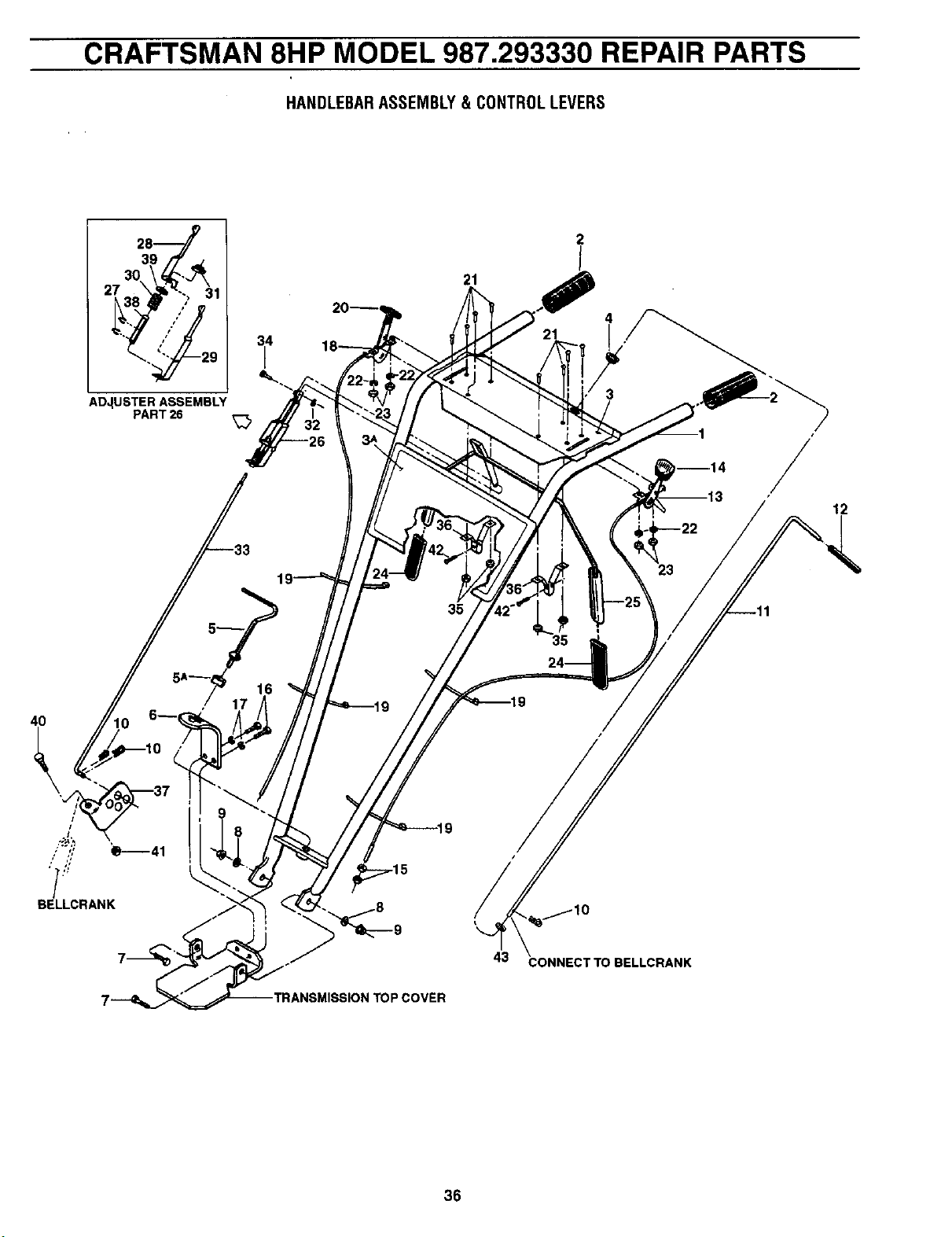
CRAFTSMAN 8HP MODEL 987.293330 REPAIR PARTS
HANDLEBARASSEMBLY& CONTROLLEVERS
2j
ADJUSTER ASSEMBLY
PART 26
34
I
21
21
4
3
12
16
4O
BELLCRANK
35
OP COVER
43 CONNECT TO BELLCRANK
36
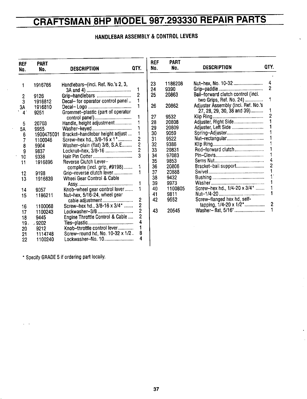
CRAFTSMAN 8HP MODEL 987.293330 REPAIR PARTS
HANDLEBARASSEMBLY& CONTROLLEVERS
REF PART
No. No. DESCRIPTION QTY.
1916766
2 9126
3 1918812
3A 1916810
' 4' 9251
5 20703
5A 9955
6 1900475001
7 1100046
8 9904
9 9837
10 9338
11 1916896
12 9198
13 1916639
14 9057
15 1186211
16 1100068
17 1100243
18 9445
19.... 9202
20 9212
21 1114748
22 1100240
Handlebars-(incl,Ref. No,'s2, 3,
3A and 4) ................................... 1
Grip-handlebars ........................... 2
Decal- for operatorcontrolpanel., 1
Decal- Logo .................................. 1
Grommet-plastic (part of operator
controlpanel)............................. 1
Handle, heightadjustment ............. 1
Washer-keyed ............................... 1
Bracket-handlebar height adjust... 1
Screw-hex hd., 3/8-16 x 1*........... 2
Washer-plain (flat) 3/8, S.A.E........ 2
Locknut-hex, 3/8-16 ..................... 2
HairPinCotter............................... 3
ReverseClutch Lever-
complete (incl. grip, #9198)....... 1
Grip-reverseclutch lever............... 1
WheelGearControl & Cable
Assy........................................... 1
Knob-wheel gearcontrol lever...... 1
Nut-hex, 5/16-24, wheelgear
cableadjustment........................ 2
Screw-hex hd., 3/8-16 x 3/4". ...... 2
Lockwaaher-3/8 ............................ 2
EngineThrottle Control& Cable.... 2
Ties-plastic.................................... 4
Knob-throttle control lever............ 1
Screw-round hd, No. 10-32 x 1/2. 8
Lockwasher-No. 10....................... 4
REF PART
No. No. DESCRIPTION QT_
23 1186208
24 9390
25 20863
26 20862
27 9532
28 20808
29 20809
30 9059
31 9522
32 9386
33 20831
34 97083
35 9853
36 20806
37 20888
38 9432
39 9973
40 1100805
41 9811
42 9552
43 20545
Nut-hex, No. 10-32 ....................... 4
Grip-paddle ................................... 2
Bail-forwardclutch control(incl.
two Grips,Ref.No. 24) .............. 1
Adjuster Assembly (incl. Ref. No.'s
27, 28, 29, 30, 38 and 39).......... 1
Kllp Ring........................................ 2
Adjuster,Right Side....................... 1
Adjuster,Left Side ......................... 1
Spring-Adjuster ............................. 1
Nut-rectangular ............................. 1
Klip Ring........................................ 1
Rod-forward clutch....................... 1
Pin-Clevis...................................... 1
SeresNut....................................... 4
Bracket-bailsupport...................... 2
Swivel............................................ 1
Bushing......................................... 1'
Washer.......................................... 1
Screw-hex hd., 1/4-20 x 3/4". ...... 1
Nut-I/4-20 .................................... 1
Screw-flanged hex hd,self-
tapping, 1/4-20 x 1/2". ............... 2
Washer- flat, 5/16"........................ 1
* SpecifyGRADE5 if orderingpart locally.
37
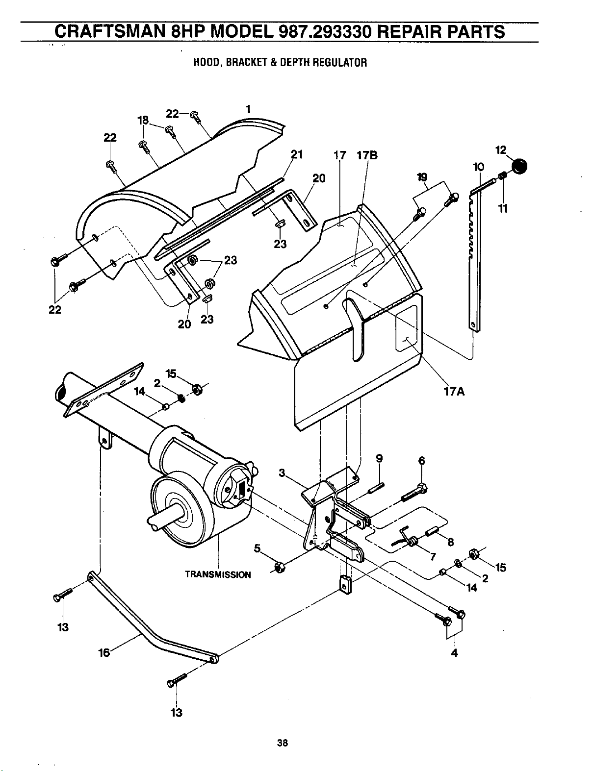
CRAFTSMAN 8HP MODEL 987.293330 REPAIR PARTS
HOOD,BRACKET& DEPTHREGULATOR
22
22
2O
23
23
21 17 17B 12
10
20 19
11
17A
9 6
13
TRANSMISSION
/
<
13
7
4
38
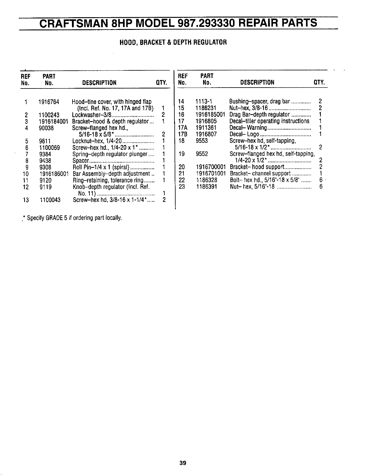
CRAFTSMAN 8HP MODEL 987.293330 REPAIR PARTS
HOOD, BRACKET& DEPTH REGULATOR
,I i
REF PART REF PART
No, NO. DESCRIPTION QTY. NO. No. DESCRIPTION QTY.
1 1916764
2
3
4
1100243
1916184001
90038
5 9811
6 1100069
7 9384
8 9438
9 9308
10 1916186001
11 9120
12 9119
13 1100043
Hood-tine cover,with hinged flap
(Incl. Ref. No. 17, 17A and 17B) 1
Lockwasher-3/8............................ 2
14 1113-1 Bushing-spacer,dragbar ............. 2
15 1186231 Nut-hex, 3/8-16 ............................ 2
16 1916185001 DragBar-depth regulator ............. 1
Bracket-hood& depth regulator... 1
Screw-flanged hexhal.,
5/16-18 x 5/8". ......................... 2
Locknut-hex, 1/4-20..................... 1
Screw-hex hd., 1/4-20 x 1*. ......... 1
Spring-depth regulator plunger.... 1
Spacer........................................... 1
Roll Pin-l/4 x 1 (spiral)................ 1
Bar Assembly-depth adjustment .. 1
Ring-retaining, tolerance ring....... 1
Knob-depth regulator (Incl. Ref.
No.11) ...................................... 1
Screw-hex hd, 3/8-16 x 1-1/4". .... 2
17 1916805
17A 1911361
17B 1916807
18 9553
19 9552
20
21
22
23
Decal-tilteroperating instructions 1
Decal- Warning............................. 1
Decal- Logo .................................. 1
Screw-hex hd, self-tapping,
5/16-18 x 1/2". .......................... 2
Screw-flanged hexhd,self-tapping,
1/4-20 x 1/2". ............................ 2
1916700001 Bracket- hood support.................. 2
1916701001 Bracket- channelsupport ............. 1
1186328 Bolt- hex hd., 5/16"-18 x 5/8"....... 6,
1186391 Nut- hex,5/16"-18 ....................... 6
* SpecifyGRADE5 iforderingpart locally.
39
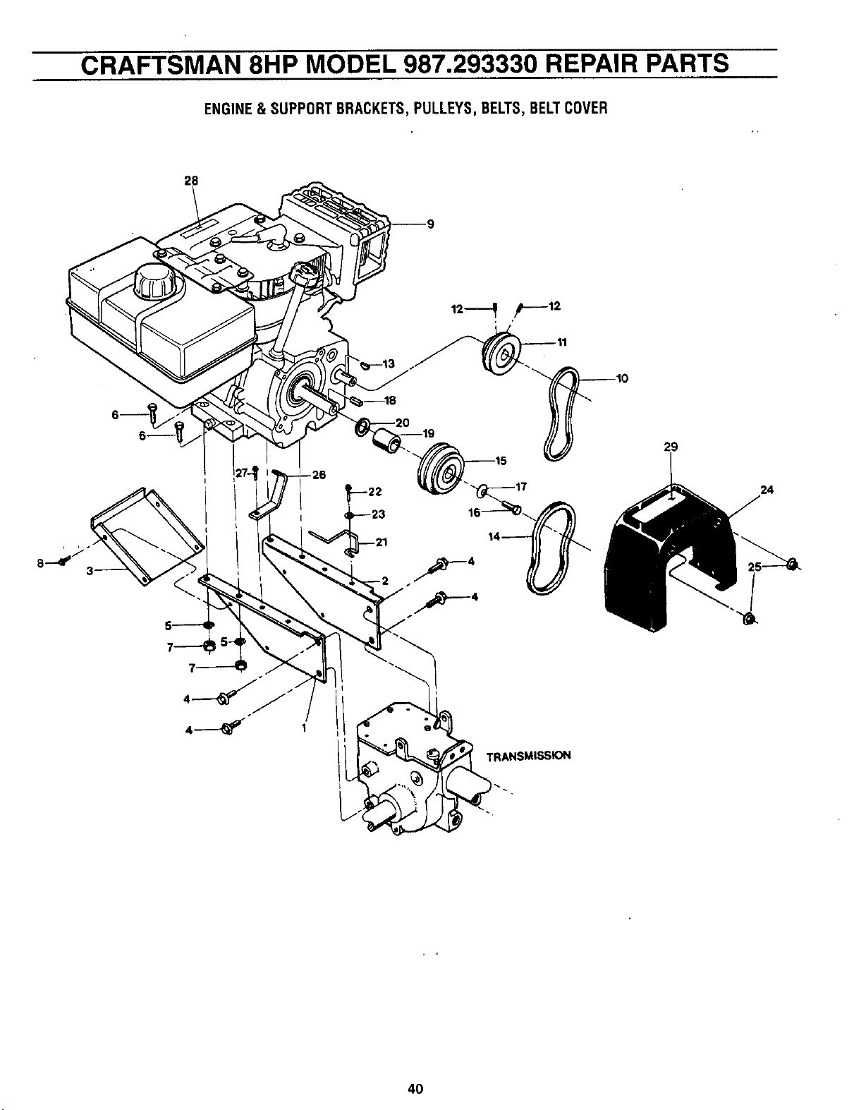
CRAFTSMAN 8HP MODEL 987.293330 REPAIR PARTS
ENGINE&SUPPORTBRACKETS,PULLEYS,BELTS,BELTCOVER
29
TRANSMISSION
/
24
4O
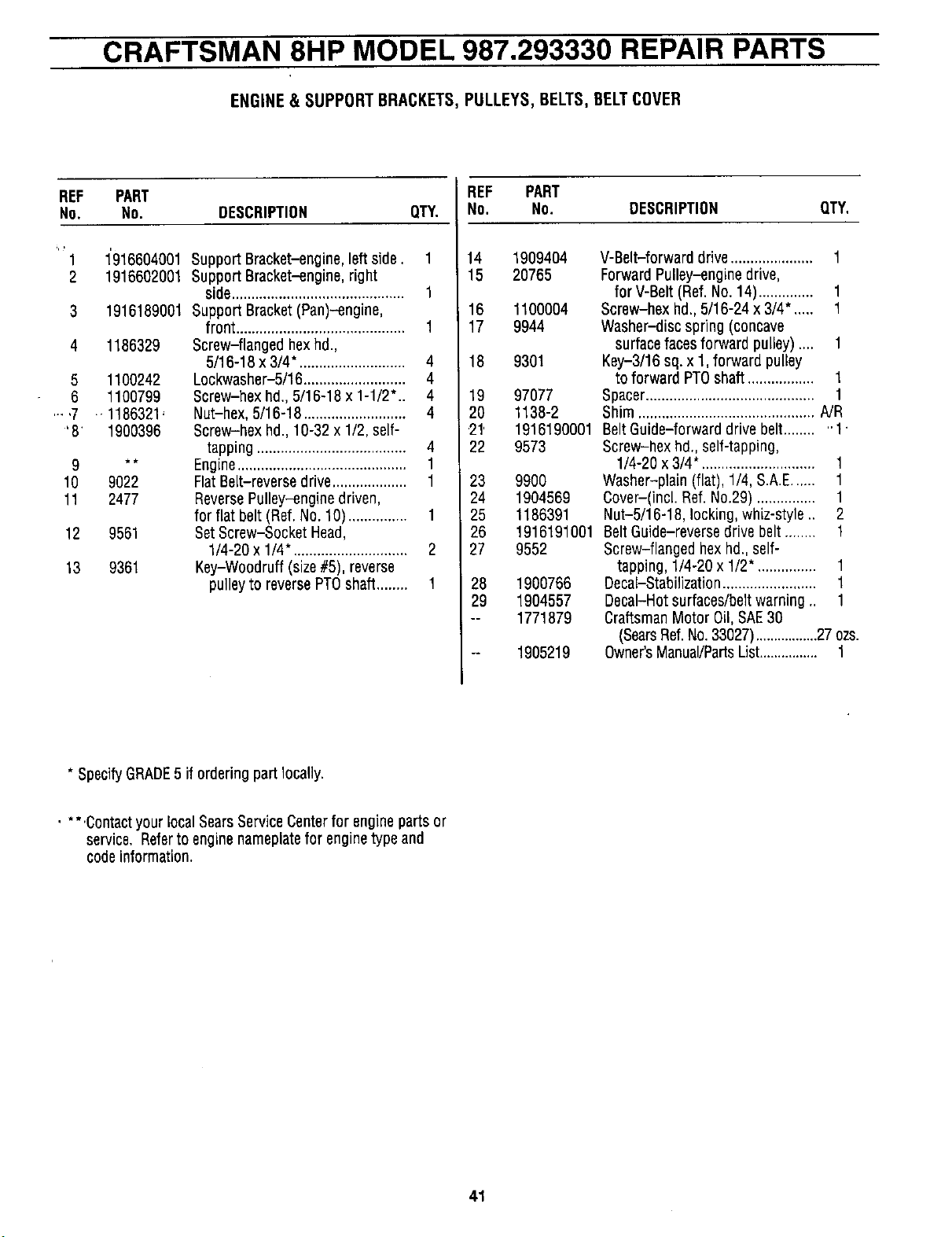
CRAFTSMAN 8HP MODEL 987.293330 REPAIR PARTS
ENGINE& SUPPORTBRACKETS,PULLEYS,BELTS,BELTCOVER
REF PART
No, No. DESCRIPTION QTY.
"'1 1'916604001
2 1916602001
3 1916189001
4 1186329
5 1100242
6 1100799
....7 .1186321'
'8' 1900396
_
10 9022
11 2477
12 9561
13 9361
Support Bracket-engine,left side. 1
Support Bracket-engine,right
side............................................ 1
Support Bracket(Pan)-engine,
front ........................................... 1
Screw-flanged hexhd.,
5/16-18 x 3/4". .......................... 4
Lockwasher-5/16.......................... 4
Screw-hex hd., 5/16-18 x 1-1/2".. 4
Nut-hex, 5/16-18 .......................... 4
Screw-hex hd., 10-32 x 1/2, self-
tapping ...................................... 4
Engine........................................... 1
Flat Belt-reverse drive................... 1
ReversePulley-engine driven,
for flat belt (Ref.No. 10)............... 1
SetScrew-Socket Head,
1/4-20 x 1/4", ............................ 2
Key-Woodruff (size#5), reverse
pulleyto reversePTOshaft........ 1
REF PART
No. NO.
14 1909404
15 20765
16 1100004
17 9944
18 9301
19
20
21'
22
23
24
25
26
27
28
29
97077
1138-2
1916190001
9573
99OO
1904569
1186391
1916191001
9552
190O766
1904557
1771879
1905219
DESCRIPTION QTY,
V-Belt-forward drive..................... 1
Forward Pulley-engine drive,
for V-Belt (Ref. No. 14).............. 1
Screw-hex bd., 5/16-24 x 3/4". .... 1
Washer-disc spring (concave
surfacefacesforward pulley).... 1
Key-3/16 sq. x 1, forward pulley
to forward PTOshaft ................. 1
Spacer........................................... 1
Shim ............................................. NR
BeltGuide-forward drive belt........ "1.
Screw-hex hal,,self-tapping,
1/4-20 x 3/4". ............................ 1
Washer-plain (flat), 1/4, S.A.E...... 1
Cover-(incl. Ref. No.29) ............... 1
Nut-5/16-18,1ocking, whiz-style .. 2
BeltGuide-reverse drivebelt ........ 1
Screw-flanged hex hd., self-
tapping, 1/4-20 x 1/2". .............. 1
Decal-Stabilization........................ 1
DecaI-Hotsurfaces/beltwarning., 1
CraftsmanMotor Oil, SAE30
(SearsRef.No.33027).................27 ozs.
Owner'sManual/PartsList................ 1
* SpecifyGRADE5 if ordering part locally.
.... Contactyour localSearsServiceCenterfor engine parts or
service, Referto engine nameplatefor enginetype and
codeinformation.
41
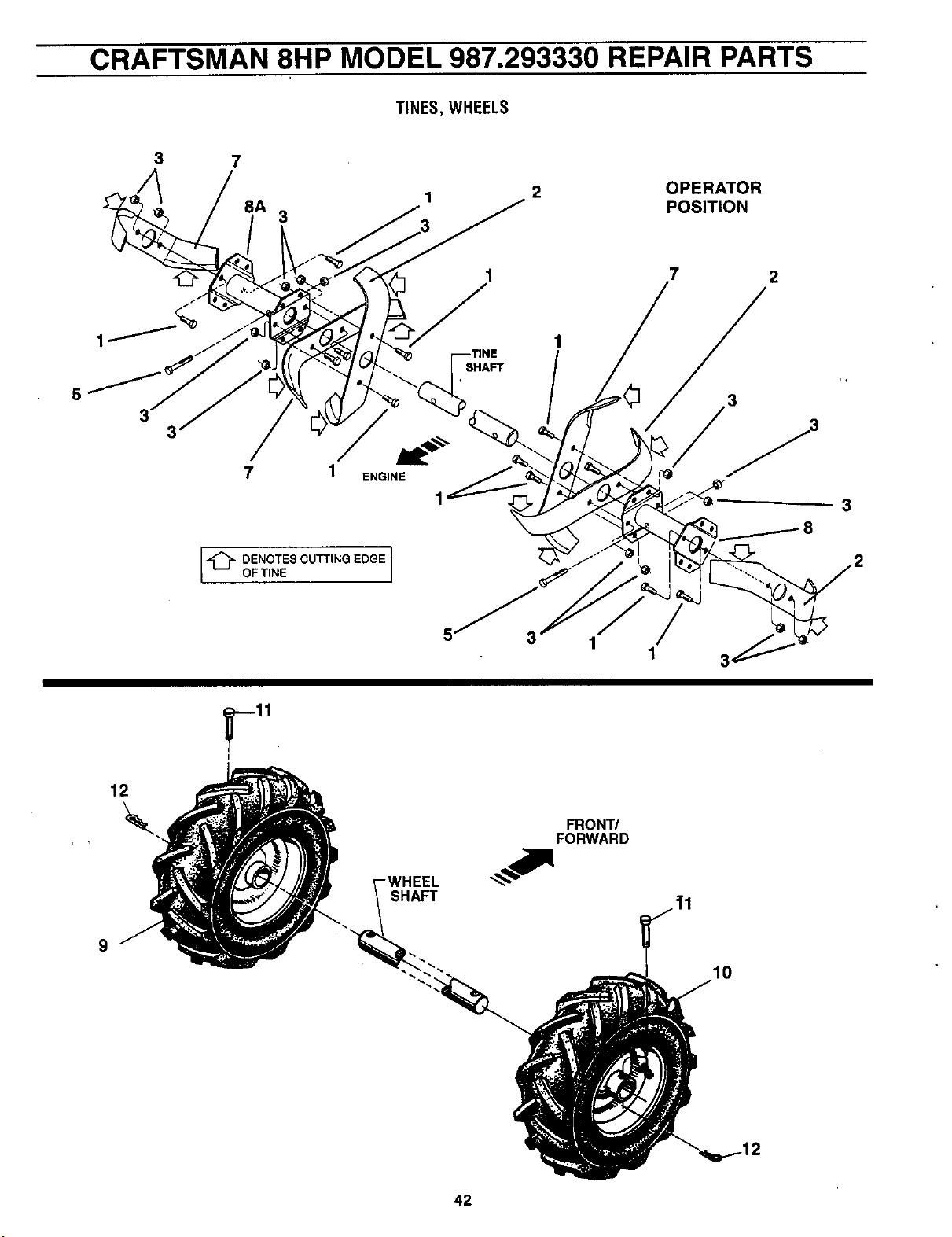
CRAFTSMAN 8HP MODEL 987.293330 REPAIR PARTS
TINES,WHEELS
5
7
8A
7
3
ENGINE
1
2
OPERATOR
POSITION
7 2
3
3
[_ ENOTES CUTTING EDGE ]
OFTINE
12
I
5
3
i
FRONT/
FORWARD
SHAFT
9
10
42
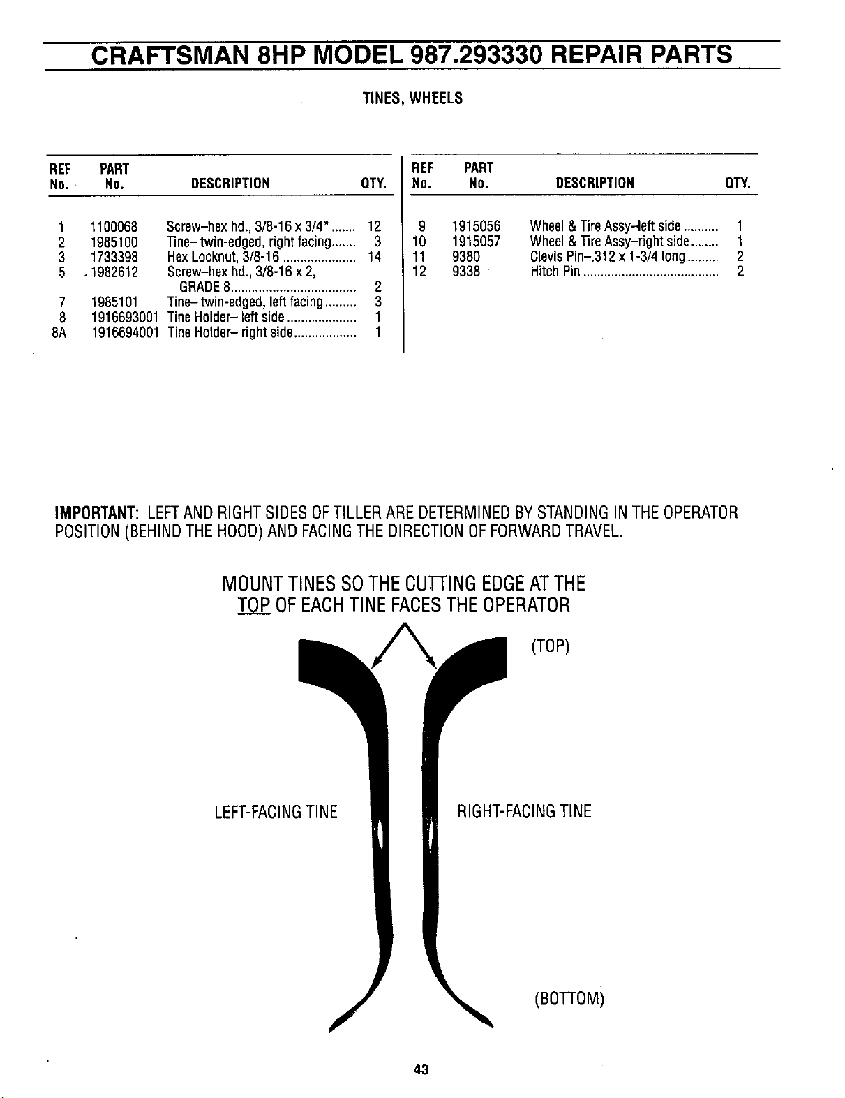
CRAFTSMAN 8HP MODEL 987.293330 REPAIR PARTS
TINES,WHEELS
REF PART
NO., No. DESCRIPTION QTY,
1 1100068 Screw-hex hd., 3/8-16 x 3/4". ...... 12
2 1985100 Tine- twin-edged, right facing....... 3
3 1733398 HexLocknut, 3/8-16 ..................... 14
5 .1982612 Screw-hex hd., 3/8-16 x 2,
GRADE8.................................... 2
7 1985101 Tine-twin-edged, left facing ......... 3
8 1916693001 Tine Holder- left side.................... 1
8A 1916694001 TineHolder- right side.................. 1
REF PART
No. No. DESCRIPTION QTY.
9 1915056 Wheel& TireAssy-left side.......... 1
10 1915057 Wheel & Tire Assy-right side........ 1
11 9380 ClevisPin-.312 x 1-3/4 long......... 2
12 9338 ' Hitch Pin....................................... 2
IMPORTANT:LEFTANDRIGHTSIDESOFTILLERAREDETERMINEDBYSTANDINGINTHEOPERATOR
POSITION(BEHINDTHEHOOD)ANDFACINGTHEDIRECTIONOFFORWARDTRAVEL.
MOUNTTINESSOTHECU.I-IINGEDGEATTHE
TOPOFEACHTINEFACESTHEOPERATOR
(TOP)
LEFT-FACINGTINE
RIGHT-FACINGTINE
(BOI-IOM)
43
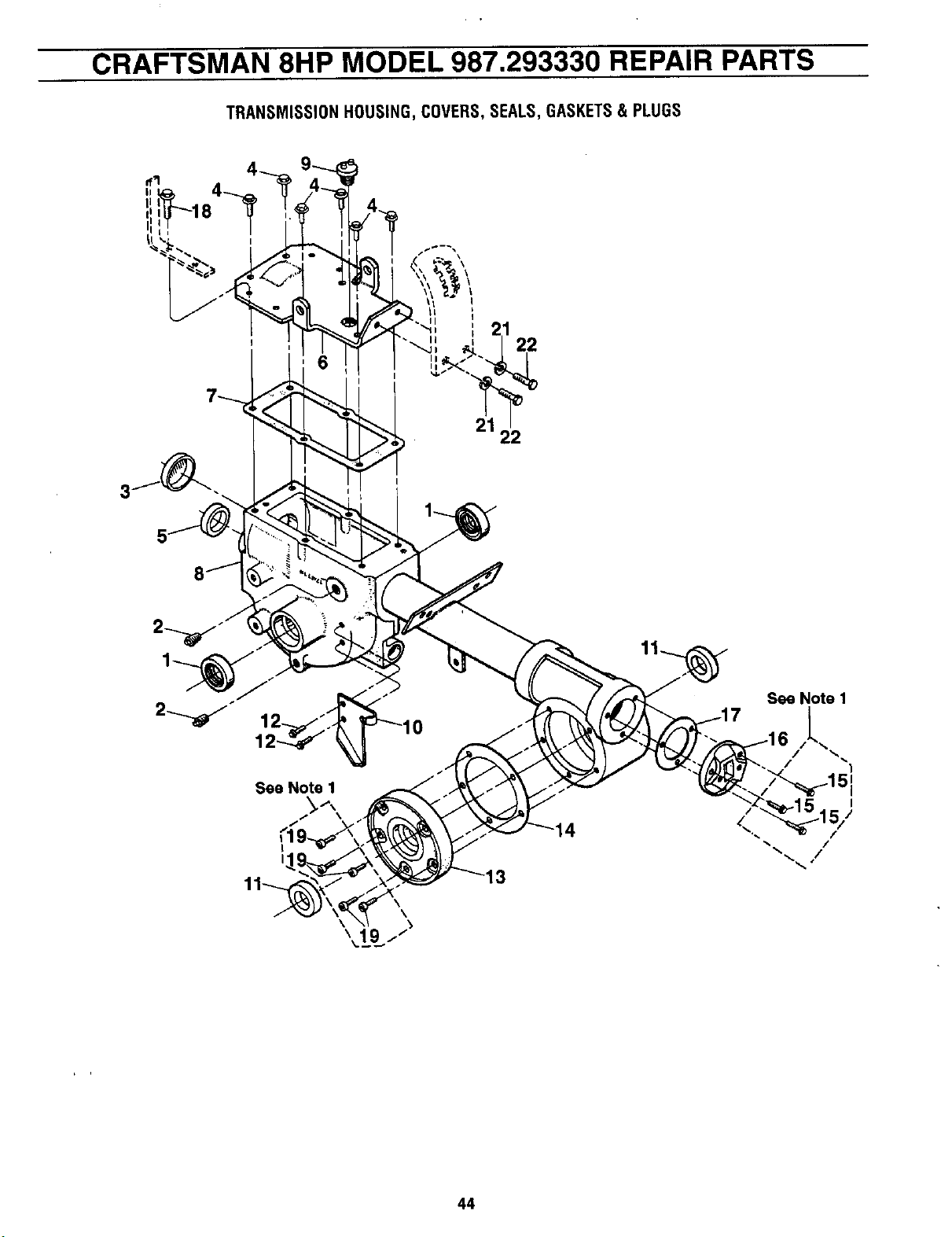
CRAFTSMAN 8HP MODEL 987.293330 REPAIR PARTS
TRANSMISSIONHOUSING,COVERS,SEALS,GASKETS& PLUGS
22
21
22
5
See Note 1
t,
14
3
See Note 1
/ I
I
44
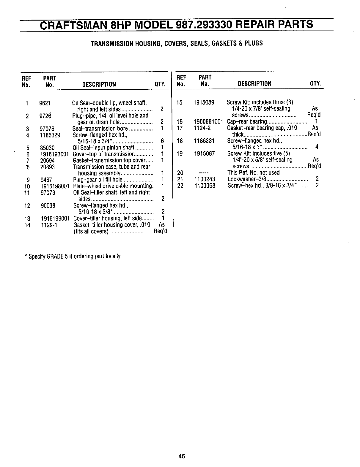
CRAFTSMAN 8HP MODEL 987.293330 REPAIR PARTS
TRANSMISSIONHOUSING,COVERS,SEALS,GASKETS& PLUGS
REF PART REF PART
No. No. DESCRIPTION QTY. No. No. DESCRIPTION QTY.
9621
9726
97076
1186329
5 85030
6 1916193001
7 20694
'8' 20893
9 9467
10 1916198001
11 97073
12 90038
13 1916199001
14 1129-1
Oil Seal-double lip, wheel shaft,
right and left sides..................... 2
Plug-pipe, 1/4, oil level hole and
gear oil drain hole...................... 2
Seal-transmission bore ................ 1
Screw-flanged hexhd.,
5/16-18 x 3/4". .......................... 6
Oil Seal-input pinion shaft............ 1
Cover-top of transmission............ 1
Gasket-transmission top cover..... 1
Transmissioncase,tube and rear
housing assembly...................... 1
Plug-gear oil fill hole .................... 1
Plate-wheel drive cable mounting. 1
Oil Seal-tiller shaft, left and right
sides.......................................... 2
Screw-flanged hexhd.,
5/16-18 x 5/8". .......................... 2
Cover-tiller housing, left side........ 1
Gasket-tiller housing cover,.010 As
(fits all covers) ........... Req'd
15
16
17
18
19
20
21
22
1915089 Screw Kit:includesthree(3)
1/4-20 x 7/8' self-sealing As
screws................................ Req'd
1900881001 Cap-rearbearing........................... 1
1124-2
1186331
1915087
1100243
1100068
Gasket-rearbearing cap,.010 As
thick...........................................Req'd
Screw-flanged hexhd.,
5/16-18 x 1". ............................. 4
Screw Kit: includesfive (5)
1/4"-20x 5/8"self-sealing As
screws ......................................Req'd
This Ref.No. not used
Lockwasher-3/8............................ 2
Screw-hex hd., 3/8-16 x 3/4". ...... 2
* SpecifyGRADE5 if ordering part locally.
45
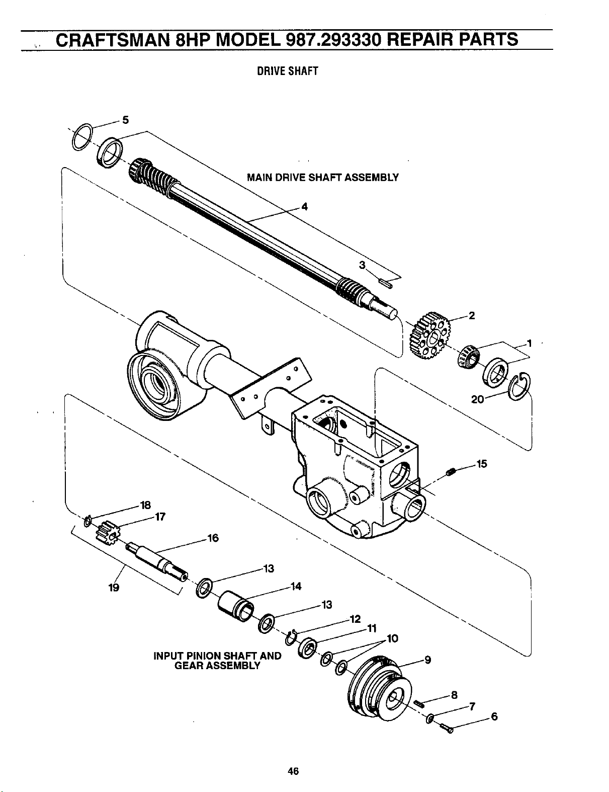
CRAFTSMAN 8HP MODEL 987.293330 REPAIR PARTS
DRIVE SHAFT
MAIN DRIVE SHAFT ASSEMBLY
19
INPUT PINION SHAFT AND
GEAR ASSEMBLY
L
46
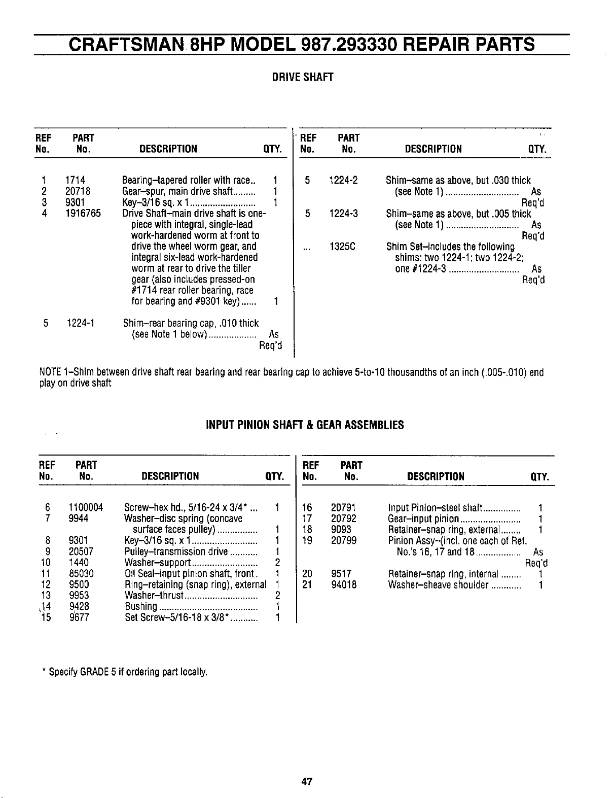
CRAFTSMAN 8HP MODEL 987.293330 REPAIR PARTS
DRIVE SHAFT
REF PART ' REF PART "
NO. NO. DESCRIPTION QTY. NO. NO. DESCRIPTION QTY.
1
2
3
4
5 1224-2
5 1224-3
... 1325C
5
1714
20718
9301
1916765
1224-1
Bearing-tapered roller with race.. 1
Gear-spur,maindrive shaft......... 1
Key-3/16 sq. x 1.......................... 1
Drive Shaft-main drive shaft is one-
piecewith integral, single-lead
work-hardened worm at front to
drive thewheel worm gear,and
integral six-lead work-hardened
worm at rearto drivethe tiller
gear (also includes pressed-on
#1714 rear roller bearing,race
for bearingand #9301 key)...... 1
Shim-rear bearing cap, .010thick
(seeNote 1 below)................... As
Req'd
Shim-same as above,but .030 thick
(seeNote 1) ............................. As
Req'd
Shim-same as above,but .005 thick
(seeNote 1) ............................. As
Req'd
Shim Set-includes the following
shims: two 1224-1; two 1224-2;
one #1224-3 ............................ As
Req'd
NOTE1-Shim betweendrive shaft rear bearing and rear bearing capto achieve5-to-10 thousandths of an inch (.005-.010) end
playon driveshaft
INPUTPINIONSHAFT& GEARASSEMBLIES
REF PART REF PART
No. No. DESCRIPTION QTY. No. NO. DESCRIPTION QTY.
1 16
17
18
19
6 1100004 Screw-hex hd.,5/16-24 x 3/4" ...
7 9944 Washer-disc spring (concave
surfacefaces pulley)................ 1
8 9301 Key-3/16 sq. x 1.......................... 1
9 20507 Pulley-transmission drive ........... 1
10 1440 Washer-support .......................... 2
11 85030 Oil Seal-input pinion shaft, front. 1
12 9500 Ring-retaining (snap ring), external 1
13 9953 Washer-thrust ............................. 2
_!4 9428 Bushing....................................... 1
15 9'677 SetScrew-5/16-18 x 3/8". .......... 1
20791
20792
9093
20799
Input Pinion-steelshaft...............
Gear-input pinion........................
Retainer-snap ring, external........
Pinion Assy-(incl. oneeachof Ref.
No.'s 16,17 and 18.................. As
Req'd
20 9517 Retainer-snap ring, internal ........ 1
21 94018 Washer-sheaveshoulder ............ 1
1
1
1
* SpecifyGRADE5 if ordering part locally.
47
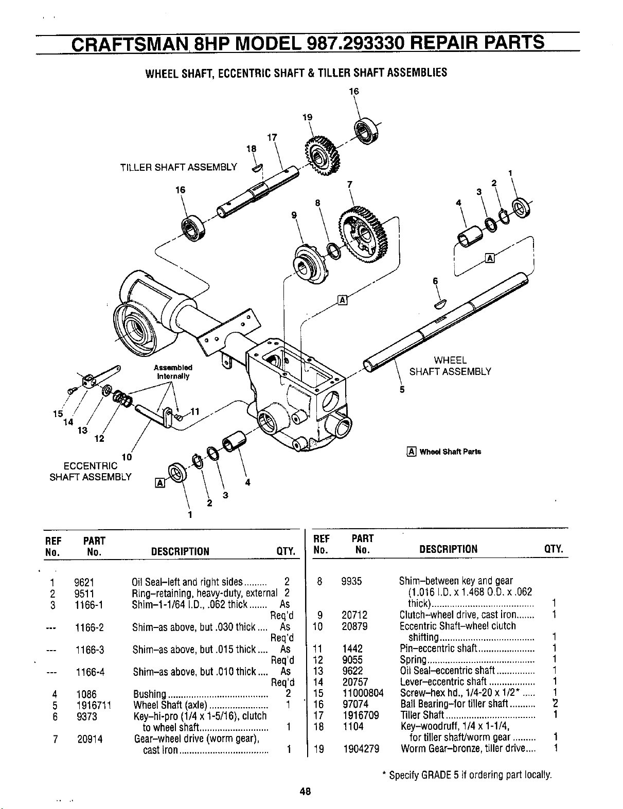
CRAFTSMAN 8HP MODEL 987.293330 REPAIR PARTS
WHEEL SHAFT, ECCENTRICSHAFT & TILLER SHAFT ASSEMBLIES
18
\
TILLER SHAFT ASSEMBLY
v I
17
16
19 ._
7
16 3
8 \ 4
1
2
6
WHEEL
SHAFT ASSEMBLY
5
[] Wheel Shaft Parts
REF PART REF PART
NO. NO. DESCRIPTION QTY. NO. NO. DESCRIPTION QTY.
1
2
3
4
5
6
9621
9511
1166-1
1166-2
1166-3
1166-4
lO86
1916711
9373
20914
0il Seal-left and right sides......... 2
Ring-retaining, heavy-duty,external 2
Shim-l-I/64 i.D.,.062 thick ....... As
Req'd
Shim-as above, but .030thick .... As
Req'd
Shim-as above, but .015thick .... As
Req'd
Shim-as above, but .010thick .... As
Req'd
Bushing....................................... 2
WheelShaft (axle)....................... 1
Key-hi-pro (1/4 x 1-5/16), clutch
to wheel shaft........................... 1
Gear-wheeldrive (worm gear),
castiron................................... 1
9935
9 20712
10 20879
11 1442
12 9055
13 9622
14 20757
15 11000804
16 97074
17 1916709
18 1104
19 19O4279
Shim-between key and gear
(1.016 I.D. x 1.468 O.D.x .062
thick)........................................ 1
Clutch-wheel drive, cast iron....... 1
EccentricShaft-wheel clutch
shifting..................................... 1
Pin-eccentric shaft...................... 1
Spring.......................................... 1
Oil Seal-eccentric shaft............... 1
Lever-eccentric shaft .................. 1
Screw-hex hd., 1/4-20 x 1/2". .... 1
Ball Bearing-for tiller shaft.......... 2
Tiller Shaft................................... 1
Key-woodruff, 1/4 x 1-1/4,
for tiller shaft/worm gear......... 1
Worm Gear-bronze,tiller drive.... 1
* SpecifyGRADE5 if ordering part locally.
48
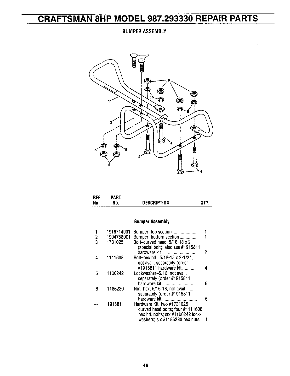
CRAFTSMAN 8HP MODEL 987.293330 REPAIR PARTS
BUMPERASSEMBLY
I
' ®
6
REF PART
No. No. DESCRIPTION QTY.
BumperAssembly
1 1916714001 8umper-top section....................
2 1904758001 Bumper-bottom section..............
3 1731025 Bolt-curved head,5/16-18 x 2
(specialbolt); also see#1915811
hardwarekit ............................. 2
4 1111608 Bolt-hex hd. 5/16-18 x 2-1/2",
not avail,separately(order
#1915811 hardwarekit ............ 4
5 1100242 Lockwasher-5/16, not avail.
separately(order #1915811
hardwarekit ............................. 6
6 1186230 Nut-hex, 5/16-18, not avail........
separately(order #1915811
hardwarekit ............................. 6
--- 1915811 HardwareKit: two #1731025
curved headbolts; four #1111608
hexhd. bolts; six #1100242 lock-
washers; six #1186230 hexnuts 1
49
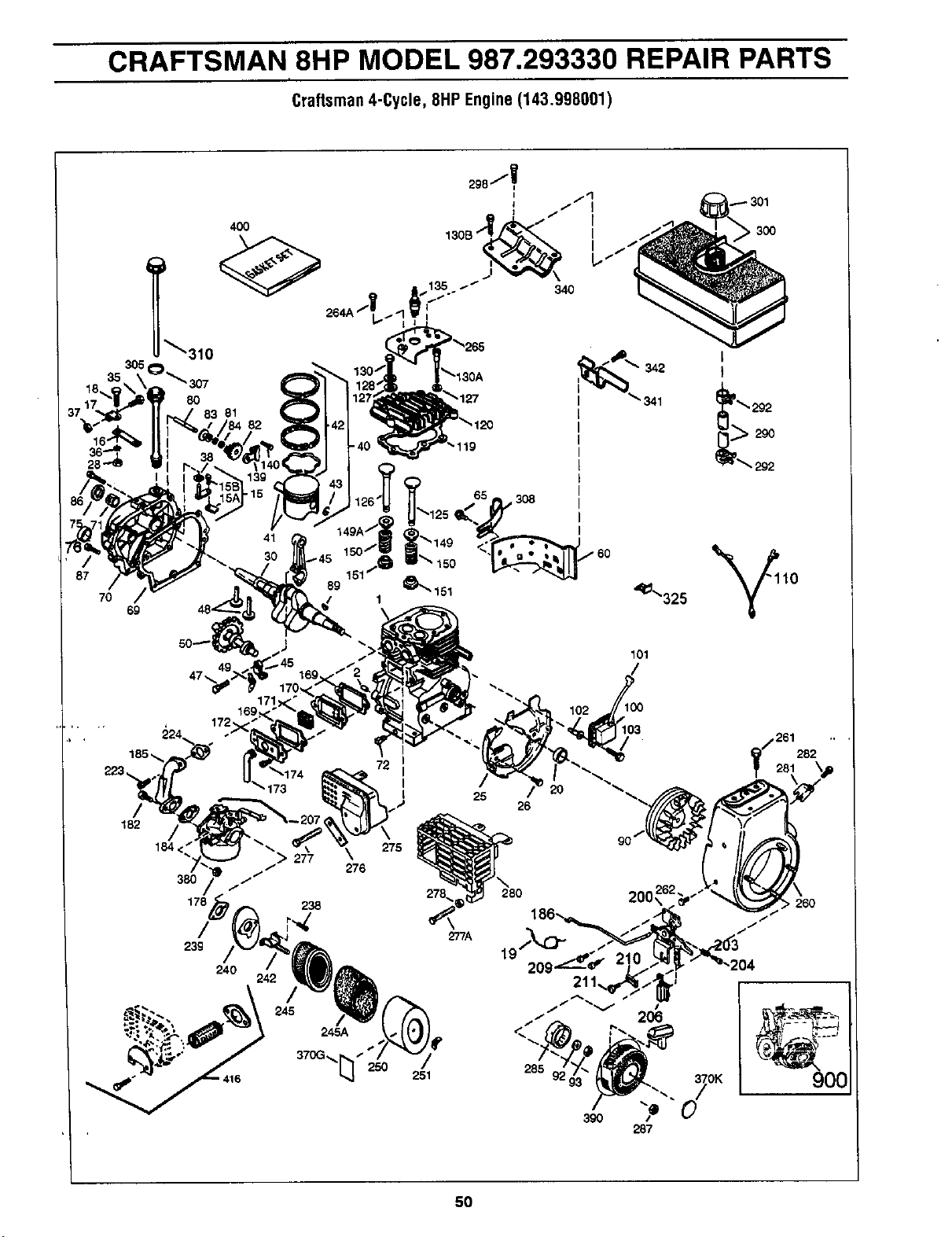
CRAFTSMAN 8HP MODEL 987.293330 REPAIR PARTS
Craftsman4-Cycle,8HPEngine(143.998001)
69
4O0
_307
8O
83 81
41
342
341
_- 301
,300
I
!
292
172,
182
276
238
/
245
245A
72 I
I
I
I
275
101
j261282 "
281
• 260
900
50
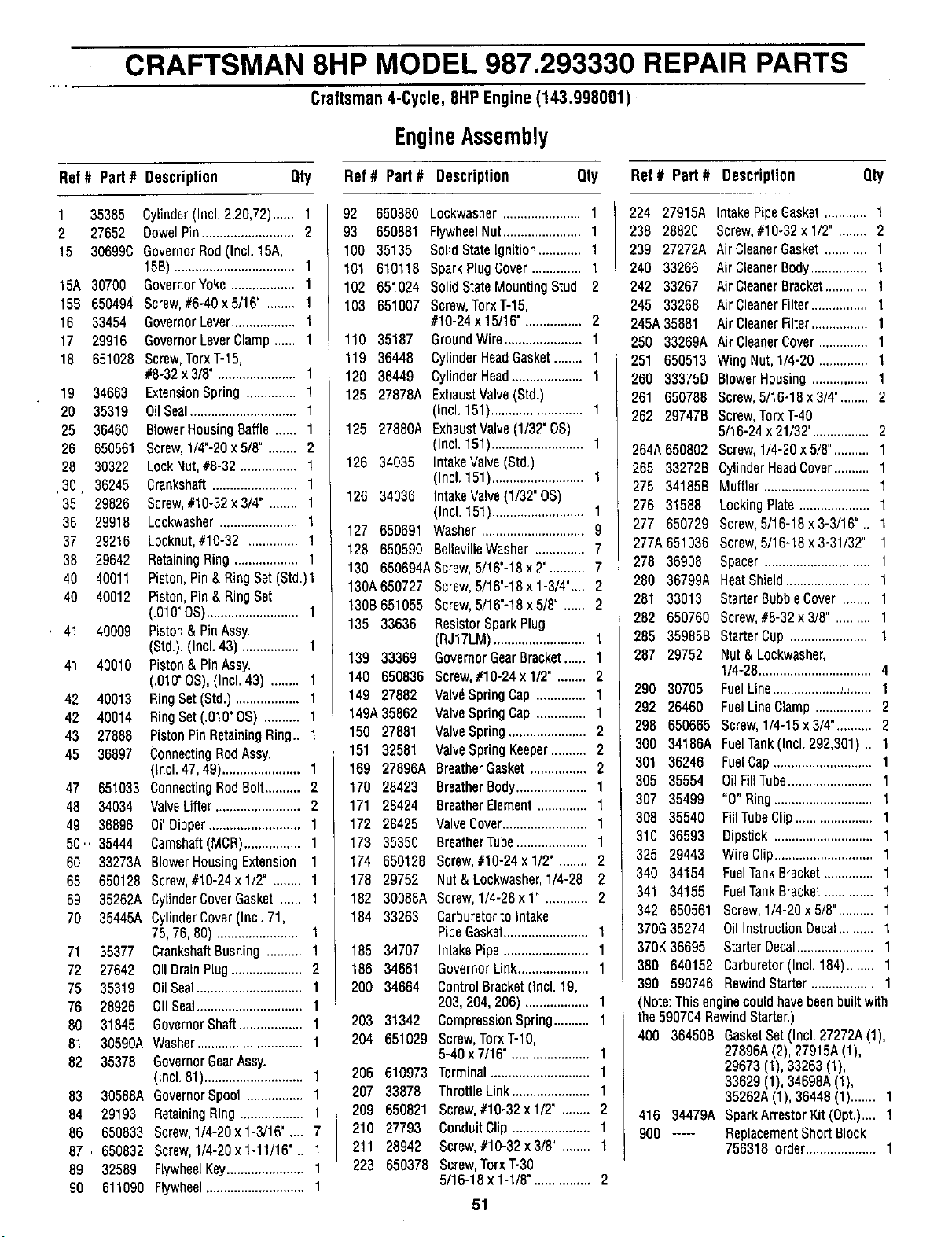
CRAFTSMAN 8HP MODEL 987.293330 REPAIR PARTS
Craftsman4-Cycle,8HP,Engine(143.998001)
EngineAssembly
Ref# Part# Description Qty Ref# Part# Description Qty Ref# Part# Description
Qty
1 35385 Cylinder(Incl.2,20,72)...... 1
2 27652 DowelPin..........................2
15 306990 GovernorRod(Incl.15A,
15B)..................................1
15A 30700 GovernorYoke.................. 1
15B 650494 Screw,#6-40x5/16" ........ 1
16 33454 GovernorLever.................. 1
17 29916 GovernorLeverClamp...... 1
18 651028 Screw,TorxT-15,
#8-32x3/8"......................1
19 34663 ExtensionSpring.............. 1
20 35319 OiiSeal..............................1
25 36460 61owerHousingBaffle...... 1
26 650561 Screw,1/4"-2Ox5/8"........ 2
28 30322 LockNut,#8-32 ................ 1
30 36245 Crankshaft........................1
35 29826 Screw,#10-32x 3/4" ........ 1
36 29918 Lockwasher......................1
37 29216 Locknut,#10-32 .............. 1
38 29642 RetainingRing.................. 1
40 40011 Piston,Pin&RingSet(Std.)l
40 40012 Piston,Pin& RingSet
(.010'OS)..........................1
. 41 40009 Piston&PinAssy.
(Std.),(Incl.43) ................ 1
41 40010 Piston&PinAssy.
(.010"OS),(Incl.43) ........ 1
42 40013 RingSet(Std.).................. 1
42 40014 RingSet(.010'0S) .......... 1
43 27888 PistonPinRetainingRing.. 1
45 36897 ConnectingRodAssy.
(Incl.47,49)......................1
47 651033 ConnectingRodBolt.......... 2
48 34034 ValveLifter........................2
49 36896 OiIDipper..........................1
50.. 35444 Camshaft(MCR)................ 1
60 33273A BlowerHousingExtension 1
65 650128 Screw,#10-24x1/2" ........ 1
69 35252A CylinderCoverGasket...... 1
70 35445A CylinderCover(Incl.71,
75,76,80) ........................1
71 35377 CrankshaftBushing.......... 1
72 27642 OiIDraLnPlug....................2
75 35319 OilSeal..............................1
76 28926 OIISeal..............................1
80 31845 GovernorShaft..................1
81 30590A Washer..............................1
82 35378 GovernorGearAssy.
(Incl.81)............................1
83 30588AGovernorSpool................ 1
84 29193 RetainingRing..................1
86 650833 Screw,1/4-20x1-3/16' .... 7
87 . 650832 Screw,1/4-20x1-11/16".. 1
89 32589 FlywheelKey......................1
90 611090 Flywheel............................1
92
93
1CO
101
102
103
110
119
120
125
125
126
126
127
128
130
130A
130B
135
139 33369
140 650836
149 27882
149A35862
150 27881
151 32581
169 27896A
170 28423
171 28424
172 28425
173 35350
174 650128
178 29752
182 30088A
184 33263
185 34707
186 34661
200 34664
203 31342
204 651029
206 610973
207 33878
209 650821
210 27793
211 28942
223 650378
650880 Lockwasher......................1
650881 FlywheelNut......................1
35135 SolidStateIgnition............ 1
610118 SparkPlugCover.............. 1
651024 SolidStateMountingStud 2
851007 Screw,TorxT-15,
#10-24x 15/16"................ 2
35187 GroundWire......................1
36448 CylinderHeadGasket........ 1
36449 CylinderHead.................... 1
27878A ExhaustValve(Std.)
(Incl.151)..........................1
27880A ExhaustValve(1/32"OS)
(Incl.151)..........................1
34035 IntakeValve(Std.)
(Incl.151)..........................1
34036 IntakeValve(1/32"0S)
(Incl.151)..........................1
650691 Washer..............................9
650590 BellevilleWasher.............. 7
650694AScrew,5/16"-18x2".......... 7
650727 Screw,5/16'-18x 1-3/4".... 2
651055 Screw,5/16"-18x5/8". ..... 2
33636 ResistorSparkPlug
(RJ17LM)..........................1
GovernorGearBracket...... 1
Screw,#10-24x1/2". ....... 2
Valv6SpringCap.............. 1
ValveSpringCap.............. 1
ValveSpring......................2
ValveSpringKeeper.......... 2
BreatherGasket................ 2
BreatherBody....................1
BreatherElement.............. 1
ValveCover........................1
BreatherTube.................... 1
Screw,#10-24x 1/2". ....... 2
Nut&Lockwasher,1/4-28 2
Screw,1/4-28x 1". ........... 2
Carburetorto Intake
PipeGasket........................1
IntakePipe........................1
GovernorLink.................... 1
ControlBracket(Incl.19,
203,204,206) .................. 1
CompressionSpring.......... 1
Screw,TorxT-IO,
5-40x7/16"......................1
Terminal............................1
ThrottleLink......................1
Screw,#10-32x1/2". ....... 2
ConduitClip......................1
Screw,#10-32x3/8". ....... 1
Screw,TorxT-30
5/16-18x 1-1/8"................ 2
51
224 27915A
238 28820
239 27272A
240 33266
242 33267
245 33268
245A35881
250 33269A
251 650513
260 33375D
261 650788
262 29747B
264A650802
265 33272B
275 34185B
276 31588
277 650729
277A651036
278 36908
280 36799A
281 33013
282 650760
285 35985B
287 29752
290 30705
292 26460
298 650665
300 34186A
301 36246
305 35554
307 35499
306 35540
310 36593
325 29443
340 34154
341 34158
342 650561
370G35274
370K36695
380 640152
IntakePipeGasket............ 1
Screw,#10-32x1/2". ....... 2
AirCleanerGasket............ 1
Air CleanerBody................ 1
Air CleanerBracket............ 1
Air CleanerFilter................ 1
Air CleanerFilter................ 1
AirCleanerCover.............. 1
WingNut,1/4-20.............. 1
BlowerHousing................ 1
Screw,5/16-18x 3/4'........ 2
Screw,TorxT-40
5/16-24x21/32'................ 2
Screw,1/4-20x 5/8".......... 1
CylinderHeadCover.......... 1
Muffler..............................1
LockingPlate....................1
Screw,5/16-18x 3-3/16".. 1
Screw,5/16-18x 3-31/32" 1
Spacer..............................1
HeatShield........................1
StarterBubbleCover ........ 1
Screw,#8-32x3/8". ......... 1
StarterCup........................1
Nut& Lockwasher,
1/4-28................................4
FuelLine..................._.,...... 1
FuelLineClamp................ 2
Screw,1/4-15x3/4".......... 2
FuelTank(Incl.292,301).. 1
FuelCap............................1
OilFillTube........................1
"0" Ring............................1
FillTubeClip......................1
Dipstick............................1
WireClip............................1
FuelTankBracket.............. 1
FuelTankBracket.............. 1
Screw,1/4-20x 5/8".......... 1
OilInstructionDecal.......... 1
StarterDecal......................1
Carburetor(Incl.184)........ 1
390 590746 RewindStarter.................. 1
(Note:Thisenginecouldhavebeenbuiltwith
the590704RewindStarter.)
400 36450B GasketSet(Incl.27272A(1),
27896A(2),27915A(1),
29673(1),33263(1),
33629(1),34698A(1),
35262A(1),36448(1)....... 1
416 34479A SparkArrestorKit(Opt.).... 1
900 ..... ReplacementShortBlock
756318,order....................1
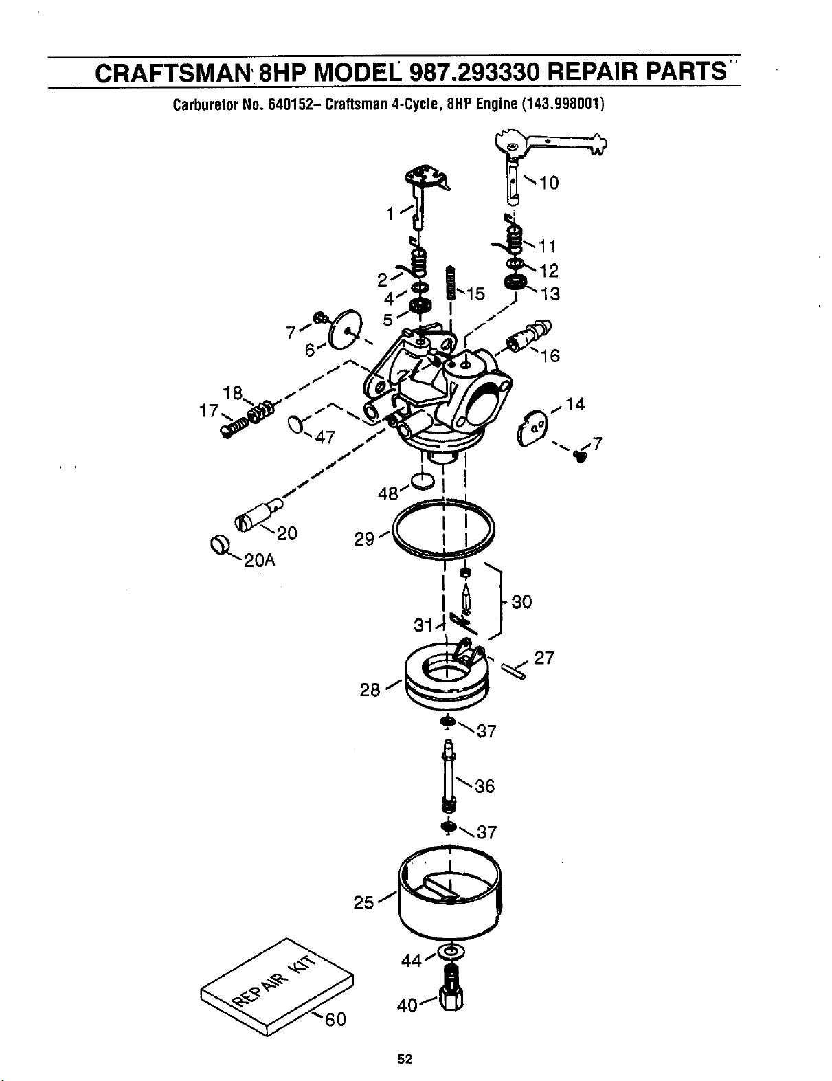
CRAFTSMAN' 8HP MODEL 987.293330 REPAIR PARTS'
CarburetorNo.640152-Craftsman4-Cycle,8HPEngine(143.998001)
6
'_37
'_37
52
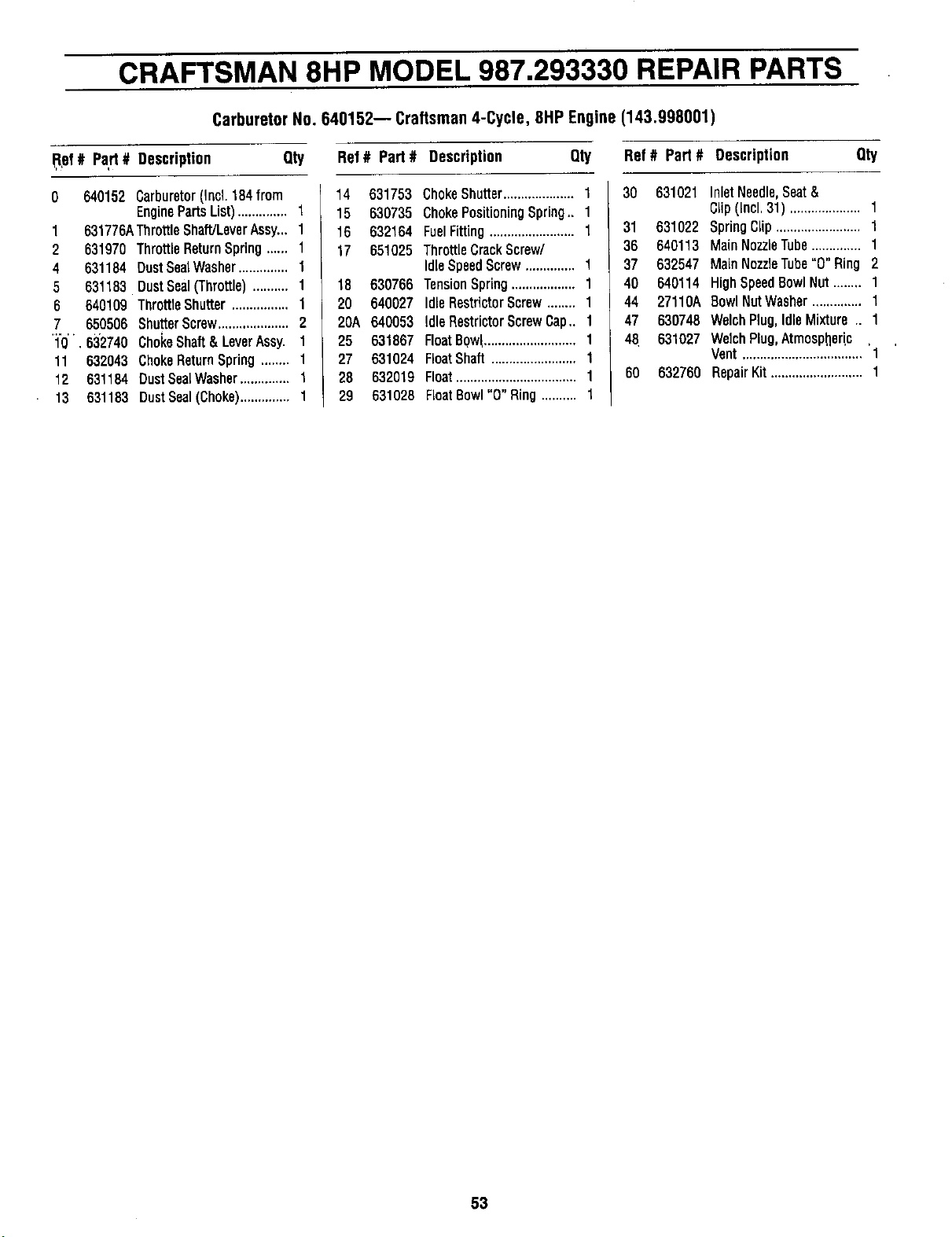
CRAFTSMAN 8HP MODEL 987.293330 REPAIR PARTS
CarburetorNo.640152-- Craftsman4-Cycle, 8HPEngine(143.998001)
,Rpf# Pa,rt# Description Qty
0 640152 Carburetor(Incl.184from
EnginePartsList).............. 1
1 631776AThrottleShaft]LeverAssy...1
2 631970 ThrottleReturnSpring...... t
4 631184 DustSealWasher.............. 1
5 631183 DustSeal(Throftle).......... 1
6 640109 ThroftleShutter................ 1
7 650506 ShufterScrew.................... 2
'1"0'', 6:32740ChokeShaft&LeverAssy. 1
11 632043 ChokeReturnSpring........ 1
12 531184 DustSealWasher.............. 1
13 631183 DustSeal(Choke).............. 1
Ref# Part# Description Qty
14 631753
15 630735
16 632164
17 651025
18 630766
20 640027
20A 640053
25 631867
27 631024
28 632019
29 631026
ChokeShutter....................1
ChokePositioningSpring.. 1
FuelFitting........................1
ThrottleCrackScrew/
IdleSpeedScrew.............. 1
TensionSpring.................. 1
IdleRestrictorScrew........ 1
IdleRestrictorScrewCap.. 1
FloatBow_..........................1
FloatShaft ........................1
Float..................................1
FloatBowl"0" Ring.......... 1
Ref# Part# Description Qty
30 631021 InletNeedle,Seat&
Clip(incl.31) .................... 1
31 631022 SpringClip........................1
36 640113 MainNozzleTube.............. 1
37 632547 MainNozzleTube"0" Ring 2
40 640114 HighSpeed8owINut........ 1
44 27110A RowlNutWasher.............. 1
47 630748 WelchPlug,IdleMixture.. 1
48 631027 WechPug,Atmospheric ,
Vent..................................1
60 632760 RepairKit..........................1
53
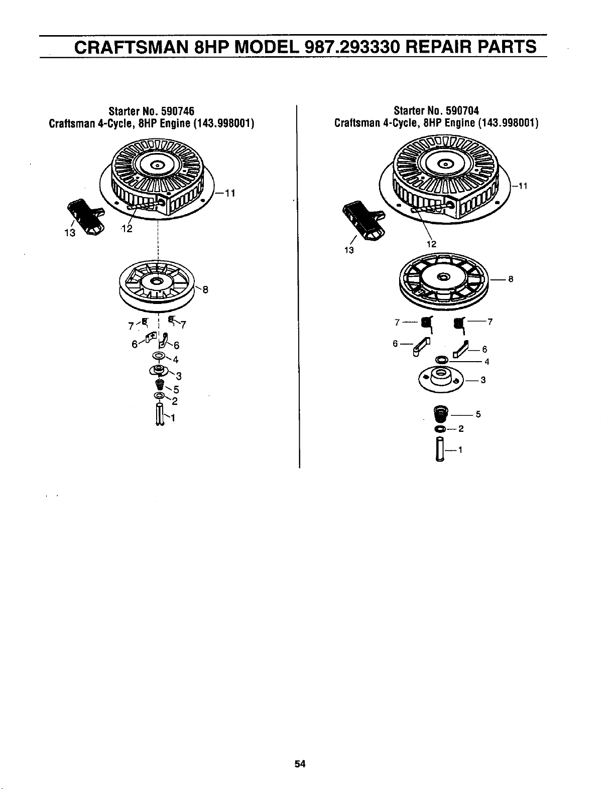
CRAFTSMAN 8HP MODEL 987.293330 REPAIR PARTS
StarterNo.590746
Craftsman4-Cycle,8HP Engine(143.998001)
13 12
'8
7_ - I I_\7
6/_.6
_"-4
m-,
StarterNo. 590704
Craftsman4-Cycle,8HPEngine(143.998001)
/ 12
13
o-('=__e
B--5
Q--2
54
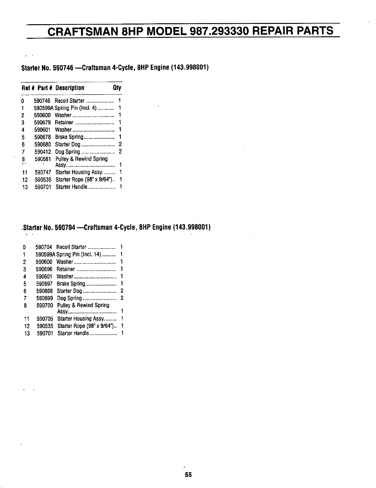
CRAFTSMAN 8HP MODEL 987.293330 REPAIR PARTS
StarterNo.590746--Craftsman 4-Cycle, 8HPEngine(143.998001)
Ref# Port# Description Qty
0 590746 RecoilStarter.................... 1
1 590599ASpringPin(Incl.4) ............ 1
2 590600 Washer..............................1
3 590679 Retainer............................t
4 590601 Washer..............................1
6 590678 BrakeSpring......................1
6 590680 StarterDog........................2
7 590412 DogSpdng........................2
8 590681 Pulley&RewindSpring
"_ Assy...................................1
11 590747 StarterHousingAssy......... 1
12 590535 StarterRspe(98"x9/64").. 1
13 590701 StarterHandle....................1
..StarterNo. 590704--Craftsman 4-Cycle, 8HPEngine(143.998001)
,b , ,
0
t
2
3
4
5
6
7
8
11
12
13
590704 RecoilStarter.................... 1
590599ASpringPin(Incl.14).......... 1
590600 Washer..............................1
590696 Retainer............................1
590601 Washer..............................1
590697 BrakeSpring...................... 1
590698 StarterDog........................2
590699 DogSpring........................2
590700 Pulley& RewindSpring
Assy...................................1
590705 StarterHousingAssy......... 1
590535 StarterRope(98"x 9/64").. 1
590701 StarterHandle.................... 1
55
For In-home major brand repair service:
Call 24 hoursa day, 7 days a week
1-800-4-MY-HOME" (1-800-469-4663)
Para pedlr eervicio de reparacl6n a domicllio - 1-800-676-5811
In Canada for all your service and parts needs call
- 1-800-665-4455
Au Canada pour tout le service ou les pi6ces
For the repair or replacement parts you need:
Call 6 am - 11 pm CST, 7 days a week
PartsDirect"
1-800-366-PART (1-800-366-7278)
Para ordenar plezas con entrega a domlcllio - 1-800-659-7084
For the location of a Sears Parts and Repair Center In your area:
Call 24 hoursa day, 7 days a week
1-800-488-1222
For Information on purchasing a Sears Maintenance Agreement
or to Inquire about an existing Agreement:
Call 9 am - 5 pm, Monday - Saturday
1-800-827-6655
SEARS
HomeCentral"
FORM 1905219 (10/98) Printed in U.S.A.