Loading ...
Loading ...
Loading ...
USER GUIDE
Control Operation-Service
USER GUIDE
Control Operation - Service 2
u-line.com
SAFETY • INSTALLATION & INTEGRATION • OPERATING INSTRUCTIONS • MAINTENANCE • SERVICE
DOOR ALERT NOTIFICATION
When the door is left open for more than 5 minutes:
• An audible tone will sound for several seconds every
minute.
• “dr” will appear in display.
Close door to silence alert and reset.
VIEWING ACTUAL TEMPERATURE
In viewing temperature in these modes any offsets are
taken into account. This means that if you place a therm-
istor in a known temperature, let’s say ice water, it may
not read the 32°F that you would assume. If the control
offset was preset at -3°F while you placed the thermistor
in an icebath, the actual thermistor reading when viewing
actual temperature would read 35°F. In the unit this would
cause the cabinet to push itself 3° cooler. To view pure
thermistor readings you must go into the service menu
and choose the correct option.
To view the thermistor temperature, push and release the
up and down keys. The display will show the corrected
refrigerator temperature.
SHOWROOM MODE
This mode is designed to show units in a display environ-
ment. When in this mode the only functions will be the
control and cabinet lights. The compressor, fans, etc. will
not operate. To enter/exit this mode hold the light key
and the power key for 5 seconds. The display will flash
once and beep and the degree symbol will begin to flash.
When the degree symbol is flashing the unit will allow the
use of the control for demonstrations. The unit can be left
in this mode indefinitely.
SERVICE MODE
This mode has options available for service diagnostics.
To enter the mode hold the hidden key for 10 seconds.
The display will show “0.” When in this mode use the up
and down arrows to select the desired option. The LIGHT
key is the ENTER key and will initiate the function. If
changing a setting, you must press the LIGHT key again
to retain the changed setting. To exit the service mode
scroll to option “0” and press the LIGHT key. After five
minutes of not touching any keys the mode will also exit
automatically.
CONTROL FUNCTION QUICK GUIDE
FUNCTION COMMAND DISPLAY/OPTIONS
ON/OFF Press and release Unit will immediately turn ON or OFF
Toggle lights
Press and release to leave interior light
on for 3 hours
Glass door wine captains and beverage centers
only.
Adjust refrigerator
temperature
Push and release
When the “F” or “C” in the display is flashing,
push to adjust the set point
temperature.
View temperature in unit Push
and release together
The display will flash and then toggle from set
point to temperature in unit.
Toggle between F/C Hold the for five seconds The display will change units.
or
or
and
and
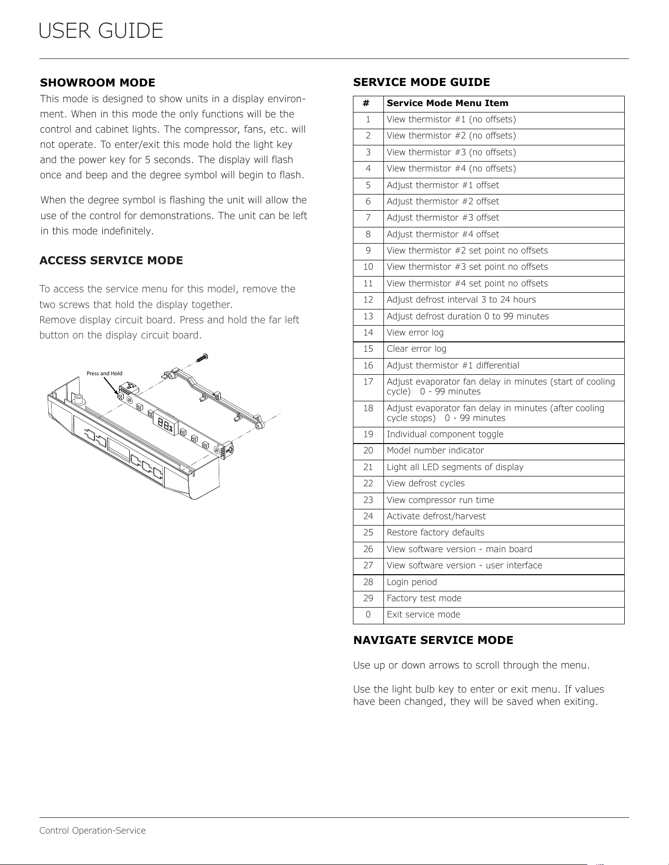
ACCESS SERVICE MODE
To access the service menu for this model, remove the
two screws that hold the display together.
Remove display circuit board. Press and hold the far left
button on the display circuit board.
Press and Hold
USER GUIDE
Control Operation - Service 3
u-line.com
SAFETY • INSTALLATION & INTEGRATION • OPERATING INSTRUCTIONS • MAINTENANCE • SERVICE
SERVICE MODE GUIDE
1. THERMISTOR 1 — ZONE
This shows the pure thermistor reading with no
offsets taken into account.
2. THERMISTOR 2 — EVAPORATOR
This shows the pure thermistor reading with no
offsets taken into account.
3. Does not apply to this model.
4. Does not apply to this model.
5. THERMISTOR 1 — ZONE OFFSET
(DO NOT MAKE AN ADJUSTMENT TO THIS WITHOUT
CONTACTING TECH LINE: +1.414.354.0300)
This calibration is only to be used if actual
temperature at thermistor #1 is off from set
point.
By adjusting the offset higher we can force the
unit to drive the temperature down below the set
point. (example: adjusting from 0 to +2 will drop
the unit temperature 2 degrees)
6. THERMISTOR 2 — EVAPORATOR OFFSET
(DO NOT MAKE AN ADJUSTMENT TO THIS WITHOUT
CONTACTING TECH LINE: +1.414.354.0300)
7. THERMISTOR 3 — AMBIENT OFFSET Not
adjustable.
8. Does not apply to this model.
9. THERMISTOR 2 — SET POINT MINUS
OFFSET
This shows the thermistor reading with offsets
taken into account.
10.Does not apply to this model.
11.Does not apply to this model.
12.ADJUST DEFROST INTERVAL — 3 TO 24
HOURS
This will adjust the interval between defrosts
from 3 to 24 hours. Adjusting from the factory
settings may cause undesired temperature in
the refrigerator section.
13.ADJUST DEFROST DURATION — 0 TO 99
MINUTES
The length of the defrost can be adjusted 0 to 99
minutes long. The other defrost parameters still
apply. Lengthening a defrost may cause higher
than normal temperatures in the refrigerator
section.
# Service Mode Menu Item
1 View thermistor #1 (no offsets)
2 View thermistor #2 (no offsets)
3 View thermistor #3 (no offsets)
4 View thermistor #4 (no offsets)
5 Adjust thermistor #1 offset
6 Adjust thermistor #2 offset
7 Adjust thermistor #3 offset
8 Adjust thermistor #4 offset
9 View thermistor #2 set point no offsets
10 View thermistor #3 set point no offsets
11 View thermistor #4 set point no offsets
12 Adjust defrost interval 3 to 24 hours
13 Adjust defrost duration 0 to 99 minutes
14 View error log
15 Clear error log
16 Adjust thermistor #1 differential
17 Adjust evaporator fan delay in minutes (start of cooling
cycle) 0 - 99 minutes
18 Adjust evaporator fan delay in minutes (after cooling
cycle stops) 0 - 99 minutes
19 Individual component toggle
20 Model number indicator
21 Light all LED segments of display
22 View defrost cycles
23 View compressor run time
24 Activate defrost/harvest
25 Restore factory defaults
26 View software version - main board
27 View software version - user interface
28 Login period
29 Factory test mode
0 Exit service mode
NAVIGATE SERVICE MODE
Use up or down arrows to scroll through the menu.
Use the light bulb key to enter or exit menu. If values
have been changed, they will be saved when exiting.
SERVICE MODE GUIDE
39
Loading ...
Loading ...
Loading ...