Loading ...
Loading ...
Loading ...
.m
WARNING
DONOTattempt any maintenance,adjustments or service
with engine and blade running. STOPengineand blade.
Disconnectspark plug wire and secure awayfrom spark
plug. Engineand components are HOT.Avoid serious
burns, allow sufficient time for all components to cool.
WheelDriveControlAdjustment
Thewheel drive control lever(A, Figure18) should engage
the transmission whenthe leveris squeezedback toward the
handlebar,and should disengagethe transmission when the
lever is released.
Figure 18. Wheeldrive controls
(Components removed for clarity)
If the transmission does not engageor disengage,
adjustment may be performed as follows:
1. Removethe rear cover from the mower. Referto the
section entitled "Rear CoverRemoval& Installation".
2. With the wheeldrive control lever in the 'DISENGAGE'
position, the spring (A, Figure19) on the end of the
wheeldrive control cable should haveno tension.
Measurethe overall length of the unextendedspring (B).
Figure 19. Measuring the disengagedtransmission spring
length
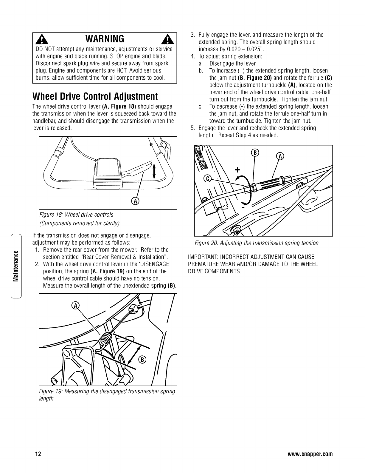
3. Fully engagethe lever,and measurethe length of the
extendedspring. The overall spring length should
increase by 0.020- 0.025".
4. Toadjust spring extension:
a. Disengagethe lever.
b. Toincrease (+)the extendedspring length, loosen
the jam nut (B, Figure20) and rotate the ferrule (C)
below the adjustment turnbuckle (A), located on the
lower end of the wheel drive control cable, one-half
turn out from the turnbuckle. Tighten the jam nut.
c. Todecrease(-) the extended spring length, loosen
the jam nut, and rotate the ferrule one-half turn in
toward the turnbuckle. Tightenthe jam nut.
5. Engagethe leverand recheckthe extendedspring
length. RepeatStep 4 as needed.
Figure20: Adjusting the transmission spring tension
IMPORTANT:INCORRECTADJUSTMENTCANCAUSE
PREMATUREWEARAND/ORDAMAGETOTHEWHEEL
DRIVECOMPONENTS.
12 www.snapper.com
Loading ...
Loading ...
Loading ...