* All Pictures In This Manual Are For Illustrative Purposes Only. Actual Product May Vary.
© 2021 United States Stove Company, 227 Industrial Park Rd., South Pittsburg, TN 37380 Ph. 800-750-2723
THIS MANUAL IS SUBJECT TO CHANGE WITHOUT NOTICE.
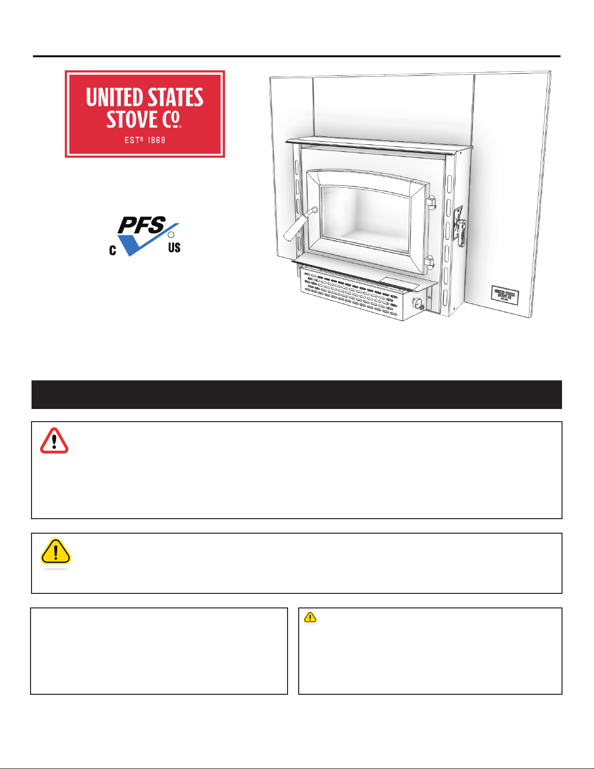
Owner’s Instruction and Operation Manual
U.S. Environmental Protection Agency
Certified to comply with 2020 particulate
emissions standards.
SAFETY NOTICE: If this heater is not properly installed, a house fire may result. For
your safety, follow the installation instructions. Never use make-shift compromises
during the installation of this heater. Contact local building or fire ocials about
permits, restrictions and installation requirements in your area. NEVER OPERATE
THIS PRODUCT WHILE UNATTENDED.
CAUTION! Please read this entire manual before you install or use your new room
heater. Failure to follow instructions may result in property damage, bodily injury, or
even death. Improper Installation Will Void Your Warranty!
Save These Instructions In A Safe Place For Future Reference.
CALIFORNIA PROPOSITION 65 WARNING:
This product can expose you to chemicals including carbon
monoxide, which is known to the State of California to cause
cancer, birth defects, and/or other reproductive harm. For
more information, go to www.P65warnings.ca.gov
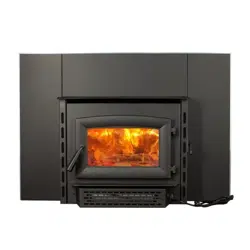
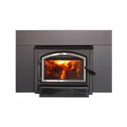
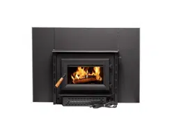
853650D-1805K
US1800E
R
Report Number: F19-552
Tested Per EPA Methods ALT-125, ASTM E2515,
ASTM E3053 and CSA B415
Certified to: UL 1482-2011 (R2015), ULC-628-93
Do not install this heater in a mobile home or trailer.
Model Number:
2
© 2021 United States Stove Company
The instructions pertaining to the installation of your wood stove comply with UL 1482-2011 (R2015) and ULC-628-
93 standards. This manual describes the installation and operation of the USSC, US1800E wood heater. This heater
meets the 2020 U.S. Environmental Protection Agency’s crib wood emission limits for wood heaters sold after May 15,
2020. Under specific test conditions this heater has been shown to deliver heat at rates ranging from 9,487 to 33,050
Btu/hr output (*1.8 g/hr and an eciency of 65.5%). Note: The BTU ratings mentioned above are based on the EPA
test protocol burning dimensional Douglas Fir lumber. Our advertised BTU’s are based on the first hour of operation at
high burn rate burning cordwood.
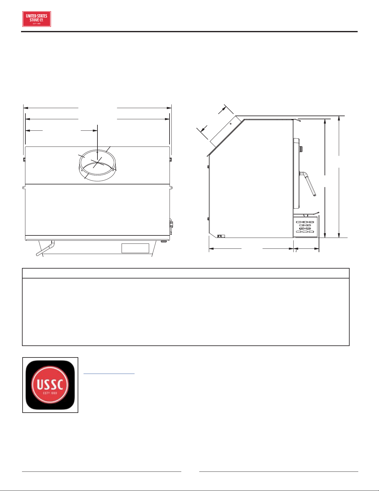
27-1/8” (691 mm)
26-1/2” (673 mm)
13-1/4” (337 mm)
6.1”
(155 mm)
21-3/4”
(553 mm)
22-3/8”
(568 mm)
15-1/2”
(394 mm)
4-11/16”
(119 mm)
CAUTIONS:
• HOT WHILE IN OPERATION. KEEP CHILDREN, CLOTHING AND FURNITURE AWAY. CONTACT MAY CAUSE
SKIN BURNS.
• DO NOT USE CHEMICALS OR FLUIDS TO IGNITE THE FIRE.
• DO NOT LEAVE THE STOVE UNATTENDED WHEN THE DOOR IS SLIGHTLY OPENED.
• DO NOT BURN GARBAGE, FLAMMABLE FLUID SUCH AS GASOLINE, NAPHTHA OR MOTOR OIL.
• DO NOT CONNECT TO ANY AIR DISTRIBUTION DUCT OR SYSTEM.
• ALWAYS CLOSE THE DOOR AFTER THE IGNITION.
For Customer Service, please call:
1-800-750-2723 Ext 5050 or;
Text to 423-301-5624 or;
Email us at:
customerservice@usstove.com
Note: Register your product online at
www.usstove.com or download the free
app today. This app is available only
on the App Store for iPhone and iPad.
Search US Stove. Save your receipt with
your records for any claims.
INTRODUCTION
© 2021 United States Stove Company
3
INSTALLATION CHECKLIST
Your Wood Stove should be installed by a qualified installer only. An NFI qualified Installer can be found at www.
nficertified.org/public/find-an-nfi-pro/
CUSTOMER SERVICE
1-800-750-2723 ext 5050
Text to 423-301-5624
Email to: Customerservice@usstove.com
COMMISSIONING CHECKLIST
This checklist is to be completed in full by the qualified person who installs this unit. Keep this page for future reference.
Failure to install and commission according to the manufacturer’s instructions and complete this checklist will
invalidate the warranty.
Please Print
Customer Name: Telephone Number:
Address:
Model:
Serial Number:
Installation Company Name: Phone Number:
Installation Technician’s Name: License Number:
DESCRIPTION OF WORK
Location of installed appliance: __________________________________________________________________________________
Chimney System: New Chimney System Yes No If yes, Brand _________________________________________
If no, Date of inspection of the existing chimney system: __________________________________________________________
COMMISSIONING
Confirm Hearth Pad Installation as per Installation Instructions ...................................................................................................
Confirm proper placement of internal parts ..........................................................................................................................................
Check soundness of door gasket and door seals .................................................................................................................................
Confirm clearances to combustibles as per installation instructions in this manual ..............................................................
Check the operations of the air controls .................................................................................................................................................
Confirm all flue pipe and chimney system are secure and sealed ..................................................................................................
Confirm the stove properly drafts when fired .......................................................................................................................................
Check to ensure a CO alarm is installed as per local building codes and is functional ............................................................
Explain the safe operation, proper fuel usage, cleaning and routine maintenance requirements ........................................
Declaration of Completion: As the qualified person responsible for the work described above, I confirm that the appliance
as associated work has been installed as per manufacturer’s instructions and following any applicable building and
installation codes.
Signed: ______________________________________ Print Name: __________________________________Date: ______________
Home Owner: RETAIN THIS INFORMATION FOR FUTURE REFERENCE
4
© 2021 United States Stove Company
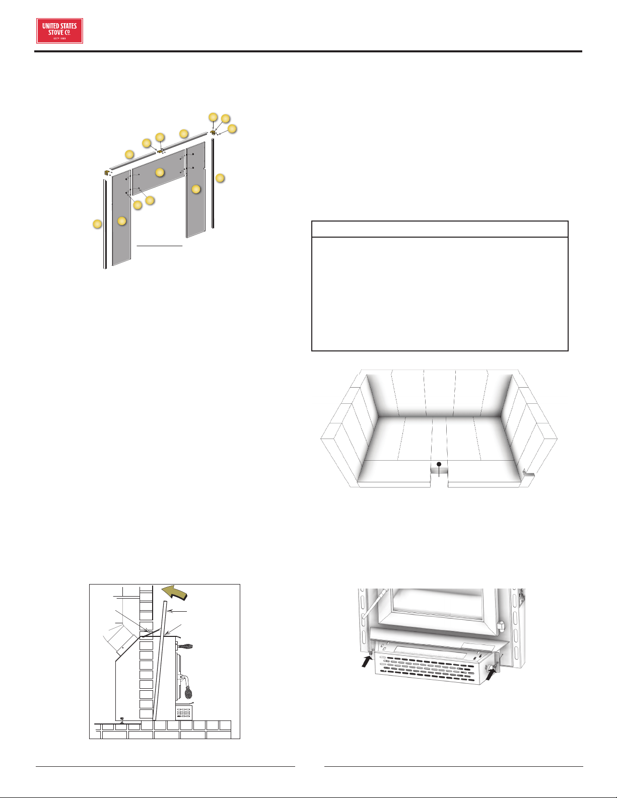
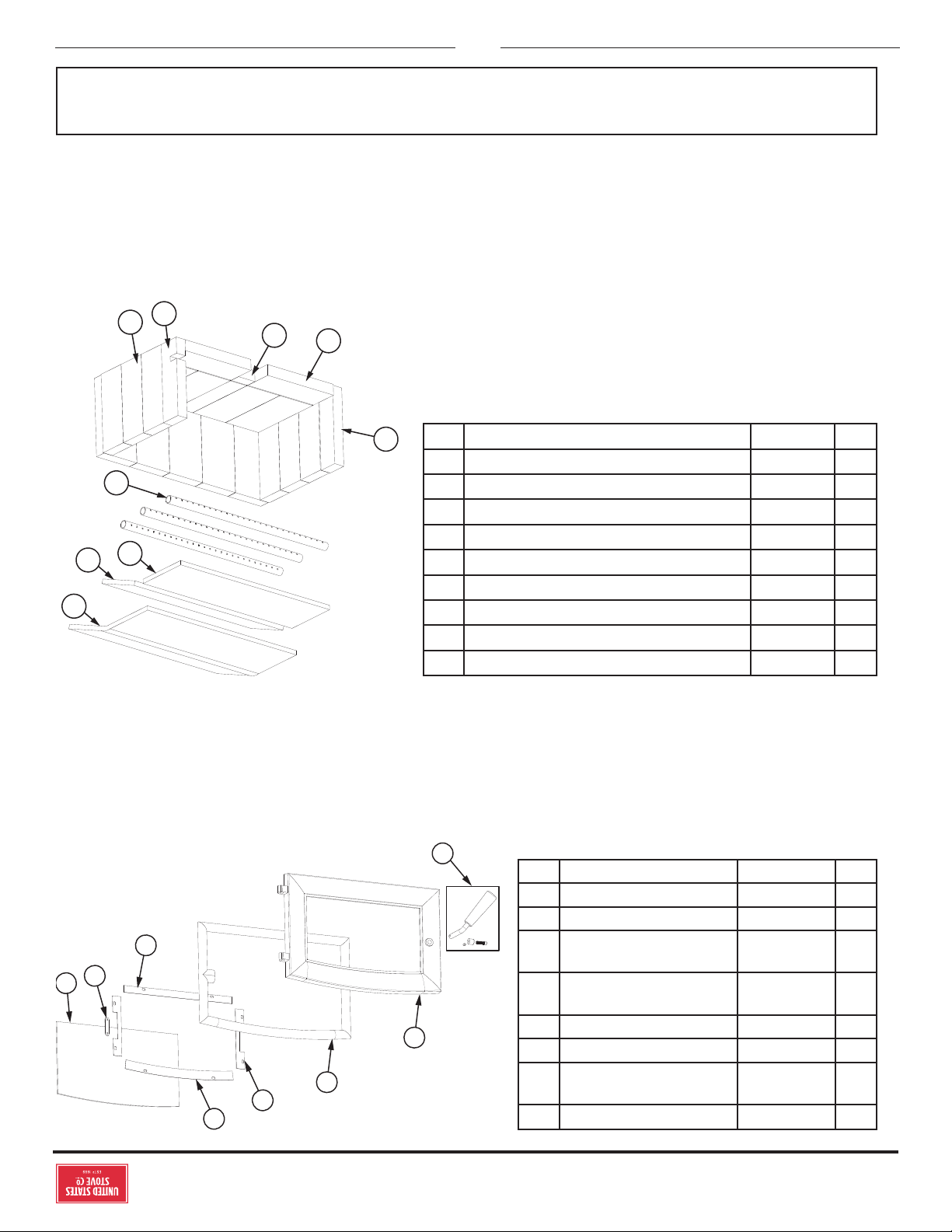
ASSEMBLY INSTRUCTIONS
ASSEMBLE THE SURROUND
a
q
b
f
e
g
h
c
d
j
k
m
n
p
SURROUND ASSEMBLY
VIEW FROM BACK
1. Lay pieces face down on carpet or other soft surface
to protect finish during assembly. The Surround
consists of two side panels, a top panel, and a
decorative trim frame.
2. Bolt the top panel (a) to the side panels (b & q) so
the top surfaces are flush to one another using items
c and d.
3. Assemble the trim frame. The trim consists of a left
(f) and right (e) side piece and a split top piece (left
h, right g). These are joined by corner connectors
(m,n,&p) and two straight center connectors (j&k).
These slide into the channel on the back of the frame
and are secured with two set screws (p) in each piece.
4. The trim slides over the surround assembly and
is secured at the base of each side with a machine
screw.
5. The Surround Assembly is then slid over the
appliance. Slots in the two side panels accommodate
the hood at the top of the appliance. The surround
assembly is held in place with two springs at the top
of either corner of the appliance.
SPRING
SURROUND
Slots in surround
slide of rebox top
Figure 6. Surround Installation
6. Connect power cord of blower to grounded receptacle.
7. Firebrick extends the life of your stove and radiates
heat more evenly. If firebricks were removed to
position appliance, replace them before firing
appliance. See figure 7 for proper orientation and
positioning. Install the back row first, then sides and
finally install bottom firebricks.
FIREBRICK INSTALLATION
CAUTION: RISK OF FIRE!
• REPLACE FIREBRICKS BEFORE FIRING
WOODSTOVE. POSITION FIREBRICKS SO NO
GAPS REMAIN BETWEEN BRICKS.
• NEVER OPERATE THIS APPLIANCE WITH
MISSING OR CRACKED FIREBRICK.
• KEEP FURNISHINGS AND OTHER COMBUSTIBLE
MATERIALS AWAY FROM THE STOVE AND
OUTSIDE MINIMUM CLEARANCES.
A
A A AD
E
A
A A A A
B
B
B
C C
F
G
B
B
B
BLOWER INSTALLATION
Remove blower assembly from packaging and check for
any damage. Notify your dealer if any damages exist.
Securely mount the blower to the heater with the two (2)
screws and washers provided.
FOR CUSTOMER SERVICE CALL: 8007502723 EXT 5050
© 2021 United States Stove Company
5
INSTALLATION
SAFETY NOTICE
• IF THIS STOVE IS NOT PROPERLY INSTALLED,
A HOUSE FIRE MAY RESULT. TO REDUCE THE
RISK OF FIRE, FOLLOW THE INSTALLATION
INSTRUCTIONS.
• CONSULT YOUR MUNICIPAL BUILDING
DEPARTMENT OR FIRE OFFICIALS ABOUT
PERMITS, RESTRICTIONS AND INSTALLATIONS
REQUIREMENTS IN YOUR AREA.
• USE SMOKE DETECTORS IN THE ROOM WHERE
YOUR STOVE IS INSTALLED.
• KEEP FURNITURE AND DRAPES WELL AWAY
FROM THE STOVE.
• NEVER USE GASOLINE, GASOLINE-TYPE
LANTERN FUEL, KEROSENE, CHARCOAL
LIGHTER FLUID, OR SIMILAR LIQUIDS TO START
OR “FRESHEN UP” A FIRE IN THIS HEATER.
KEEP ALL SUCH LIQUIDS WELL AWAY FROM
THE HEATER WHILE IT IS IN USE.
• IN THE EVENT OF A CHIMNEY FIRE, TURN THE
AIR CONTROLS TO THE CLOSED POSITION,
LEAVE THE BUILDING AND CALL THE FIRE
DEPARTMENT IMMEDIATELY!
• DO NOT CONNECT TO ANY AIR DISTRIBUTION
DUCT OR SYSTEM.
• A SOURCE OF FRESH AIR INTO THE ROOM OR
SPACE HEATED SHALL BE PROVIDED WHEN
REQUIRED.
• DO NOT INSTALL THIS APPLIANCE IN A MOBILE
HOME, MANUFACTURED HOME, TRAILER OR
TENT (NO EXCEPTIONS PER HUD FEDERAL
STANDARD: 24 CFR CH.XX).
WARNING:
VERIFY THAT THE APPLIANCE IS PROPERLY
INSTALLED BEFORE FIRING FOR THE FIRST
TIME. THIS APPLIANCE SHOULD BE INSTALLED
BY A QUALIFIED INSTALLER TO ENSURE A
CORRECT AND SAFE INSTALLATION. NEVER USE
TEMPORARY OR MAKESHIFT COMPROMISES
DURING THE INSTALLATION.
WARNING:
PROVIDE ADEQUATE COMBUSTION AIR TO THE
ROOM WHERE THE APPLIANCE IS INSTALLED.
RESTRICTING COMBUSTION AIR WILL RESULT IN
A LAZY FIRE WHICH CAUSES SOOT OR CREOSOTE
BUILDUP AND GREATLY REDUCES EFFICIENCY.
WARNING:
DO NOT CONNECT A WOOD BURNING APPLIANCE
TO AN ALUMINUM TYPE B GAS VENT. THIS IS
NOT SAFE. USE APPROVED MASONRY OR A UL
103 HT (U.S.) LISTED RESIDENTIAL TYPE AND
BUILDING HEATING APPLIANCE CHIMNEY. USE A
6” DIAMETER CHIMNEY, THAT IS HIGH ENOUGH
TO CREATE SUFFICIENT DRAFT.
US Stove highly recommends your stove be installed by a
qualified NFI (US) or WETT (Canada) technician. To find
the nearest qualified installer, go to:
https://nficertified.org,
https://www.wettinc.ca/
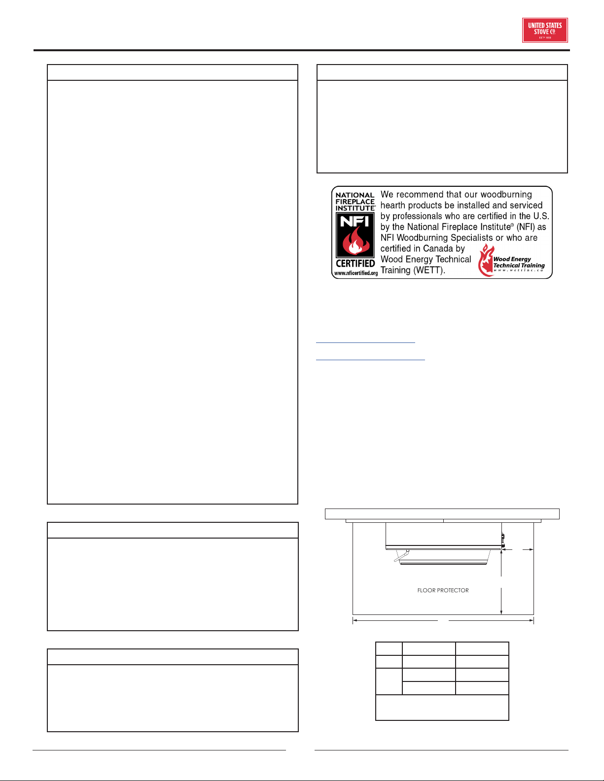
FLOOR PROTECTOR
A solid non-combustible floor, concrete or solid masonry,
must extend 6” (153 mm) to either side of the body of the
appliance and 17” (432 mm) in front of the face of the
appliance. When combustible flooring falls within these
minimum dimensions, it must be covered with a listed
floor protector, with an R-Value of at least 1.4. Check local
building codes if you want to finish the floor covering with
grouted ceramic floor tile.
C
B
Minimum Floor Protector Specifications
A
FLOOR PROTECTOR
A 17” 432 mm
B *6” *153 mm
C
38” U.S.A. 966 mm
42” CAN. 1067 mm
* = Canadian installations
requires 8” (204 mm)
6
© 2021 United States Stove Company
CLEARANCES TO COMBUSTIBLES
WARNING: RISK OF FIRE
OBSERVE THE MINIMUM CLEARANCES TO
COMBUSTIBLES STATED IN THIS MANUAL AND
ON THE LABELS ATTACHED TO THE APPLIANCE.
DO NOT STORE WOOD, ANY TYPE OF FLAMMABLE
VAPORS OR LIQUIDS, PLACE FURNITURE, RUGS,
CARPET, CLOTHING OR OTHER COMBUSTIBLE
OBJECTS WITHIN THE CLEARANCE AREA.
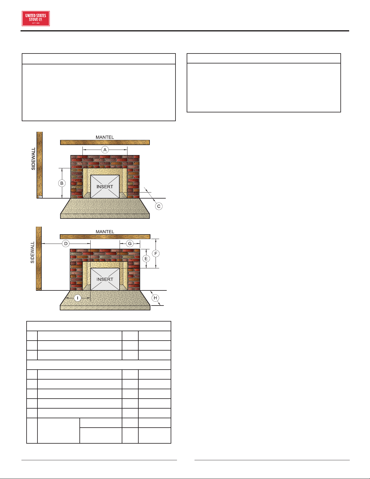
Fireplace Opening Dimensions
A Minimum Width 29” 737 mm
B Minimum Height 23” 585 mm
C Minimum Depth 14” 356 mm
Clearance to Combustibles
D Min. Distance to Sidewall 9” 229 mm
E Min. Distance to Top Trim 14” 356 mm
F Min. Distance to Mantle 19” 483 mm
G Min. Distance to Side Trim 9” 229 mm
H Min. Floor Protector Front 17” 432 mm
I
Min. Floor
Protector
Side
USA 6” 153 mm
Canada 8” 204 mm
OUTSIDE COMBUSTION AIR
WARNING:
ALWAYS CONNECT THIS APPLIANCE TO A
CHIMNEY THAT VENTS TO THE OUTSIDE. NEVER
VENT INTO ANOTHER ROOM, CRAWL SPACE,
ATTIC, OR INSIDE A BUILDING. DO NOT CONNECT
THIS UNIT TO A CHIMNEY FLUE SERVING
ANOTHER APPLIANCE.
Your appliance itself does not create draft. Draft is
provided by the chimney. To help provide the required
draft there is a fresh air kit (4FAK) available for purchase
from your local stove dealer. When installed properly
the 4FAK kit is designed to provide the draft needed for
proper operation. To achieve proper draft your chimney
must meet the three minimum height requirements (see
masonry chimney section of this manual). A minimum
draft of 0.05 w.c. (measured in water column) is required
for proper drafting to prevent back pung, smoke spillage,
and to maximize performance. Gauges to measure draft
are readily available at stove stores and are economical
to rent or purchase. Factors such as wind, barometric
pressure, trees, terrain and chimney temperature can
have an adverse eect on the draft. The manufacturer
cannot be held responsible for external factors leading
to less than optimal drafting. Should you have a problem
with inadequate draft, you should contact a licensed
heating and cooling contractor for assistance in solving
the problem.
FIREPLACE CONDITION AND ZERO
CLEARANCE REQUIREMENTS
A masonry fireplace must meet minimum code
requirements, National Fire Protection Association,
(NFPA) 211, or the equivalent for a safe installation.
Contact a professional, licensed installer, your local
building inspector or the local fire authority for the
requirements in your area. Your insurance company
should be able to recommend a qualified inspector.
Inspections should include the following:
1. Condition of the fireplace and chimney. A masonry
fireplace and chimney MUST be inspected prior to
installation of this appliance. They must be free from
cracks, loose mortar, creosote deposits, blockage
or other evidence of deterioration. If found, these
items MUST be repaired prior to installation. DO NOT
REMOVE BRICKS or MORTAR from existing fireplace
when installing this unit.
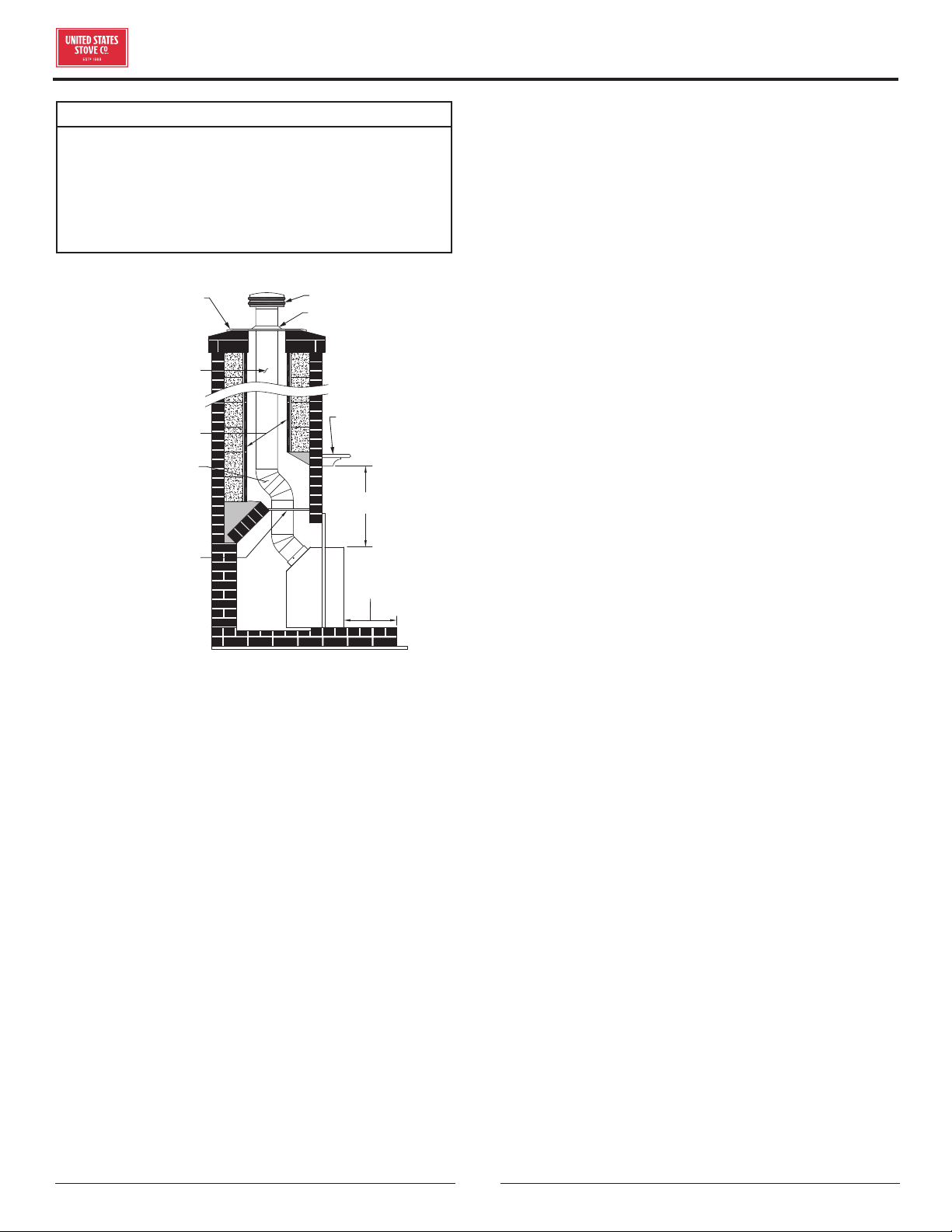
2. Chimney Size. Minimum chimney size is 6” (153
mm) diameter. Maintain a 15 ft. minimum overall
INSTALLATION
© 2021 United States Stove Company
7
chimney height measured from the top of appliance
to the top of the chimney. Chimneys must extend at
least 3 ft. above the roof and at least 2 ft. above the
highest point within 10 ft. of the chimney top. See the
Chimney Connections section of this manual.
3. Zero Clearance or Metal Heatform Fireplaces. These
fireplaces and chimneys must meet the minimum
code specifications as noted above. Factory built
zero clearance fireplaces must be listed and suitable
for solid fuel use. Chimneys must be at least 7 inch
diameter to accommodate a required, continuous,
stainless steel liner from the appliance’s flue collar to
the top termination of the chimney. Only detachable
parts that can be easily replaced (i.e. damper parts,
screens, doors and side, and back refractory panels)
are to be removed. These parts must be stored and
readily available for replacement if the appliance is
ever removed. The removal of any parts that render
the fireplace unusable for burning solid fuel requires
a permanent label to be axed by the installer that
states the fireplace is unsuitable for burning solid
fuel unless the missing parts are replaced and the
fireplace is restored to its original, certified condition.
4. Chimney Caps. Mesh type chimney caps and spark
arrestors must be able to be removed for regular
inspection and cleaning. Otherwise the mesh should
be removed to prevent possible plugging. Check your
local fire and building codes.
5. Chimney Liner. The chimney must be suitable for
burning solid fuel. Install a continuous stainless steel
liner from the flue collar of the appliance to the top of
the chimney. Liner must be UL Listed to UL1777.
6. Combustible Material Clearances. The fireplace and
chimney must be inspected to make sure there is
adequate clearance to combustible materials. This
includes the top, side, front, and back as well as
concealed combustibles in the chimney and mantle
areas. Your local building inspector or fire authority
should have information on whether older fireplace
meet current codes and are suitable for use.
7. Makeup Air Requirements. This appliance requires
an adequate supply of makeup air to operate safely
and eciently. In some areas, this is a building code
requirement. Inadequate air supply will cause poor
combustion, inecient operation, creosote buildup,
back drafting and smoke pung into the living areas.
If any of the following conditions are evident, a
makeup air supply MUST be installed.
a. Existing fuel-fired equipment shows evidence of
back pung, smoke roll-out, inecient operation, or
excessive smell in the living area.
b. Opening a window or door alleviates any of the above
problems or symptoms.
c. The building is constructed with a well-sealed vapor
barrier, tight fitting windows, or has powered exhaust
fans.
d. Excessive condensation on windows in the winter.
e. The building has a ventilation system installed.
f. If, once installed, the solid-fuel appliance does not
draw steadily, burns poorly or ineciently, back-
drafts or experiences back-pung when adding fuel.
VENTING (DRAFT) REQUIREMENTS
WARNING:
RISK OF FIRE - EXCESSIVE DRAFT CAN CAUSE
OVERFIRING AND A POSSIBLE STRUCTURE FIRE.
DO NOT OPERATE THIS APPLIANCE WITH THE
FLUE DRAFT EXCEEDING 0.06 in. w.c. (0.1 Pa).
The chimney flue is a critical component to the proper
and ecient operation of any heating appliance. Heating
appliances do not create draft, draft is provided by the
chimney. This appliance requires a draft of 0.05” water
column (0.1 Pa) at the flue collar. To achieve proper
draft, your chimney must meet three minimum height
requirements; minimum height from top of appliance (15
ft. total height from top of appliance), minimum height
above roof penetration (3 ft.), and minimum height (2 ft.)
above highest point of roof within a 10 ft. diameter from
the chimney. The chimney must also meet minimum and
maximum cross sectional requirements. For that reason
a continuous 6” stainless steel liner from the flue collar
to the top of the chimney is required. A stainless steel
adapter is recommended for fastening the stainless
steel liner to the flue collar. The male (or crimped) end
of the adapter must be installed inside the flue collar
to allow condensation or creosote in the liner to drain
back into the firebox. Chimney liners and/or adapters
must be permanently fastened using a minimum of
three (3) screws at each connection. Chimneys outside
of the home or on an exterior wall are dicult to keep
at operating temperatures and may result in increased
creosote buildup, less draft, back drafting problems and
poor appliance performance and should be avoided.
INSTALLATION
8
© 2021 United States Stove Company
WARNING: RISK OF FIRE
DO NOT ALLOW COMBUSTIBLE MATERIALS
(CARPET, FURNITURE, FUELS) TO BE PLACED
ON OR COVER THE FLOOR PROTECTOR. ALL
COMBUSTIBLE MATERIALS MUST REMAIN
OUTSIDE OF THE MINIMUM CLEARANCE
DIMENSIONS.
Masonry Fireplace
RAIN CAP
COVER PLATE
(non-combustible)
seal cover plate
with silicone.
UL 1777 STAINLESS
STEEL LINER
Extend to the top of
chimney cap. Follow
the manufacture’s
installation
instructions
MASONRY
CHIMNEY FLUE
6” FLEX FLUE PIPE
SEAL SMOKE
CHAMBER
Smoke chamber
must be sealed with
non-combustible
material to prevent
re-entry of smoke
into the living area.
Accomodations for
inspection and
cleaning must be
maintained.
FLOOR
PROTECTION
Observe min.
clearances
Observe min.
clearances
Mantel
(Combustible)
STORM
COLLAR
1. Clean the fireplace opening properly disposing of
any ashes in a closed metal container. See Safety
Instructions.
2. Install a 6” (153 mm) minimum diameter, continuous
stainless steel chimney liner into the existing
chimney. The liner must extend to the top of the
existing chimney. Use only listed chimney liners that
meet UL 1777(US) or ULC S635 (Canada).
3. Remove or lock the fireplace damper in the open
position. Note: Masonry or damper plate may be
removed to accommodate the chimney liner provided
this does not weaken any structural components
of the existing fireplace or chimney nor reduces
protection of combustible materials required by
national building codes. Consult with your local
building or fire authority before doing this.
4. Uncrate the appliance, remove all packing materials,
and any items stored in the firebox.
5. WARNING: Any fireplace which has had parts
removed or modified to accommodate the installation
of this appliance MUST have a warning plate
permanently installed in a visible location stating
that the fireplace is unfit for use with solid fuel. This
unit came with a metal warning label. Permanently
attach the warning plate to a visible location in the
fireplace. After choosing a visible location in the
fireplace, permanently attach the warning plate by
screwing or nailing it into place. Note: Use the holes
in the label to mark and predrill the holes needed for
attaching the label.
6. Position the appliance into the fireplace opening until
the top lip of the air jacket is flush with the fireplace
facing.
7. Level the appliance with the adjusting screws at the
rear of the appliance.
8. Connect the chimney liner to the appliance using a
stainless steel adapter and securing with a minimum
of three (3) sheet metal screws. The liner MUST
be attached with the male (or crimped) end of the
adapter inside the flue collar of the appliance to allow
condensation and/or creosote to drain back into the
firebox.
This appliance must be connected to a listed Stainless
Steel Liner, that meets UL1777, which extends from the
collar to the chimney cap according to the specifications
listed on the previous pages. Take into account the
chimney’s location to ensure it is not too close to
neighbors or in a valley which may cause unhealthy or
nuisance conditions.
CHIMNEY DRAFT
NOTE: A DRAFT READING OF 0.05[12.45] to 0.06[14.94]
(Water Column[Pascals]) IS REQUIRED FOR PROPER
BURNING OF THIS APPLIANCE.
Draft is a function of the chimney, NOT THE APPLIANCE
— Do not expect the appliance to draw. Smoke spillage
into the house or excess buildup of condensation or
creosote in the chimney are warnings that the chimney
is NOT functioning properly. Correct the problem before
using the appliance. Following are some possible causes
for improper draft.
1. The connector pipe may be pushed into the chimney
too far, stopping the draft.
2. If the chimney is operating too cool, water will
condense in the chimney and run back into the
appliance. Creosote formation will be rapid and
may block the chimney. Operate the appliance at
a fire level high enough to keep the chimney warm
preventing this condensation.
3. If the fire burns well but sometimes creates
excessive smoke or burns slowly, it may be caused
by the chimney top being lower than another part of
INSTALLATION
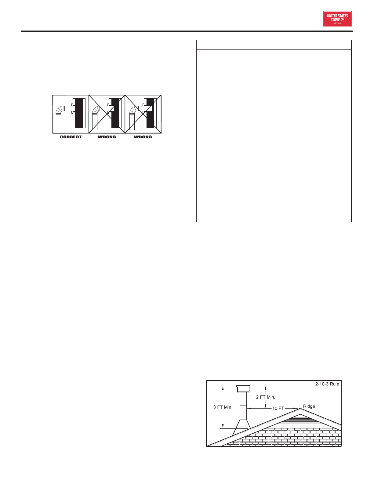
© 2021 United States Stove Company
9
the house or a nearby tree. The wind blowing over a
house or tree falls on top of the chimney like water
over a dam, beating down the smoke. The top of the
chimney should be at least three (3) feet above the
roof and be at least two (2) feet higher than any point
of the roof within ten (10) feet.
IMPORTANCE OF PROPER DRAFT
Draft is the force which moves air from the appliance
up through the chimney. The amount of draft in your
chimney depends on the length of the chimney, local
geography, nearby obstructions and other factors. Too
much draft may cause excessive temperatures in the
appliance. Inadequate draft may cause backpung into
the room and “plugging” of the chimney. Inadequate
draft will cause the appliance to leak smoke into the room
through appliance and chimney connector joints. An
uncontrollable burn or excessive temperature indicates
excessive draft.
Chimneys perform two functions:
1. As a means of exhausting smoke and flue gases
which are the result of fuel combustion.
2. The chimney provides “draft,” which allows oxygen
to be continuously introduced into the appliance, so
that proper combustion is possible. This stove relies
on natural draft to operate.
NOTICE: Always provide a source of fresh air into the
room where the stove is located. Failure to do so may
result in air starvation of other fuel burning appliances
and the possible development of hazardous conditions,
fire, or death.
IMPORTANT INSTALLATION POINTS
1. Size chimney flue to appliance collar. This stove
requires a minimum 6” diameter flue.
2. Never connect this unit to a chimney serving another
appliance.
3. The chimney must meet all minimum height
requirements.
4. Never use a chimney to ventilate a cellar or basement.
Contact your local building authority for approved
methods of installation and any necessary permits and/
or inspections.
WARNING:
• BE SURE YOUR CHIMNEY IS SAFELY
CONSTRUCTED AND IN GOOD REPAIR. HAVE
THE CHIMNEY INSPECTED BY THE FIRE
DEPARTMENT OR A QUALIFIED INSPECTOR.
YOUR INSURANCE COMPANY SHOULD BE ABLE
TO RECOMMEND A QUALIFIED INSPECTOR.
• CANADA INSTALLATIONS REQUIRES THAT
THIS FIREPLACE MUST BE INSTALLED WITH
A CONTINUOUS CHIMNEY LINER OF 6 INCH
DIAMETER EXTENDING FROM THE FIREPLACE
INSERT TO THE TOP OF THE CHIMNEY. THE
CHIMNEY LINER MUST CONFORM TO THE
CLASS 3 REQUIREMENTS OF CAN/ULC-S635,
STANDARD FOR LINING SYSTEMS FOR
EXISTING MASONRY OR FACTORY-BUILT
CHIMNEYS AND VENTS, OR CAN/ULC-S640,
STANDARD FOR LINING SYSTEMS FOR NEW
MASONRY CHIMNEYS.
• PERMANENTLY SEAL ANY OPENING BETWEEN
THE MASONRY OF THE FIREPLACE AND THE
FACING MASONRY.
MASONRY CHIMNEY
Before using an existing masonry chimney, clean the
chimney, inspect the flue liner, and make any repairs
needed to be sure it is safe to use. As mentioned
previously, this appliance requires a continuous stainless
steel liner from the appliance collar to the chimney cap.
Make repairs before attaching the stove. The connector
stove pipe and fittings you will need to connect directly
to a masonry chimney are detailed in the installation
instructions. If the fireplace chimney must go through
a combustible wall before entering the main chimney,
consult a qualified mason or chimney dealer regarding
proper materials that meet all local building and fire
authority codes. The installation must conform to local
building and fire codes and latest edition of NFPA 211. If
there is a cleanout opening in the base of the chimney,
close it tightly.
INSTALLATION
10
© 2021 United States Stove Company
OPERATION INSTRUCTIONS
OPERATING SAFETY PRECAUTIONS
• NEVER OVERFIRE THIS APPLIANCE BY
BUILDING EXCESSIVELY HOT FIRES AS A
HOUSE/BUILDING FIRE MAY RESULT. YOU ARE
OVERFIRING THE APPLIANCE IF IT BEGINS TO
GLOW OR TURN RED.
• DO NOT TAMPER WITH THE COMBUSTION AIR
CONTROL OF THIS UNIT BEYOND NORMAL
ADJUSTMENT RANGE.
• NEVER BUILD EXCESSIVELY LARGE FIRES IN
THIS TYPE OF APPLIANCE AS DAMAGE TO THE
FIREBOX OR SMOKE LEAKAGE MAY RESULT.
• DO NOT BUILD FIRE TOO CLOSE TO THE GLASS.
• HOT WHILE IN OPERATION. KEEP CHILDREN,
CLOTHING, AND FURNITURE AWAY. CONTACT
MAY CAUSE SKIN BURNS. DO NOT TOUCH THE
APPLIANCE UNTIL IT HAS COOLED.
• PROVIDE ADEQUATE AIR FOR COMBUSTION
TO THE ROOM WHERE THE APPLIANCE IS
INSTALLED.
• INSPECT CHIMNEY LINER EVERY 60 DAYS.
REPLACE LINER IMMEDIATELY IF IT IS RUSTING
OR LEAKING SMOKE INTO THE ROOM.
• ATTEMPTS TO ACHIEVE HEAT OUTPUT
RATES THAT EXCEED HEATER DESIGN
SPECIFICATIONS CAN RESULT IN PERMANENT
DAMAGE TO THE HEATER.
• TO PREVENT INJURY, DO NOT ALLOW ANYONE
TO USE THIS APPLIANCE THAT IS NOT
FAMILIAR WITH ITS CORRECT OPERATION. DO
NOT OPERATE THIS APPLIANCE WHILE UNDER
THE INFLUENCE OF ALCOHOL OR DRUGS.
• IF THERE ARE ANY MISSING OR DAMAGED
COMPONENTS OF THE APPLIANCE, CONTACT
YOUR DEALER IMMEDIATELY. DO NOT OPERATE
THIS APPLIANCE WITH MISSING OR DAMAGED
PARTS.
CAUTIONS: HOUSE FIRE HAZARDS
• DO NOT STORE WOOD ON FLOOR PROTECTOR,
UNDERNEATH STOVEPIPE(S) OR ANYWHERE
WITHIN CLEARANCES TO COMBUSTIBLE
SURFACES SPECIFIED FOR THIS APPLIANCE.
• NEVER OPERATE WITH SECONDARY TUBES,
FIBERBOARD, OR INSULATION REMOVED.
CAUTIONS:
CHILDREN SHOULD BE ALERTED TO THE HAZARDS
FROM HIGH SURFACE TEMPERATURES. NEVER
LEAVE SMALL CHILDREN UNSUPERVISED WHEN
THEY ARE IN THE SAME ROOM AS THE APPLIANCE
DURING OPERATION. TO PREVENT BURNS,
ALWAYS WEAR PROTECTIVE CLOTHING, LEATHER
HEARTH GLOVES, AND EYE PROTECTION WHEN
REFUELING OR FIRE MAINTENANCE. ALWAYS BE
AWARE OF HEATED SURFACES. HEAT RADIATING
FROM THE APPLIANCE CAN POTENTIALLY
DISCOLOR, MELT, OR EVEN IGNITE COMBUSTIBLE
MATERIALS. KEEP ALL COMBUSTIBLE MATERIALS
WELL AWAY FROM THE HEATER!
WARNING: EXPLOSION HAZARD
• NEVER USE CHEMICALS, GASOLINE, GASOLINE-
TYPE LANTERN FUEL, KEROSENE, CHARCOAL
LIGHTER FLUID, OR SIMILAR FLAMMABLE
LIQUIDS TO START OR “FRESHEN UP” A FIRE IN
THE APPLIANCE.
• KEEP ALL FLAMMABLE LIQUIDS, ESPECIALLY
GASOLINE, OUT OF THE VICINITY OF THE
APPLIANCE - WHETHER IN USE OR IN STORAGE.
WOOD STOVE UTILIZATION
Your heating appliance was designed to burn well
seasoned natural wood only; no other materials should
be burned. Any type of well seasoned natural wood
may be used in your stove, but specific varieties have
better energy yields than others. Higher eciencies and
lower emissions generally result when burning air dried
seasoned hardwoods, as compared to softwoods or too
green or freshly cut hardwoods. The following resources
can assist in learning the burn characteristics of various
species of wood:
http://firewoodresource.com/firewood-btu-ratings/; or
https://forestry.usu.edu/forest-products/wood-heating
The operation of this wood heater in a manner
inconsistent with the owner’s manual will void your
warranty and is also against federal regulations. Waste
and other flammable materials should not be burned in
your stove. DO NOT BURN:
1. Garbage;
2. Lawn clippings or yard waste;
3. Materials containing rubber, including tires;
4. Materials containing plastic;
NEVER OPERATE THIS PRODUCT WHILE UNATTENDED

© 2021 United States Stove Company
11
OPERATION INSTRUCTIONS
5. Waste petroleum products, paints or paint thinners,
or asphalt products;
6. Materials containing asbestos;
7. Construction or demolition debris;
8. Railroad ties or pressure-treated wood;
9. Manure or animal remains;
10. Saltwater driftwood or other previously salt water-
saturated materials;
11. Unseasoned wood; or
12. Paper products, cardboard, plywood, or particleboard.
The prohibition against burning these materials does
not prohibit the use of fire starters made from paper,
cardboard, sawdust, wax, and similar substances to
start a fire in an aected wood heater.
Burning these materials may result in the release of toxic
fumes or render the heater ineective and cause smoke.
Deadwood lying on the forest floor should be considered
wet and requires full seasoning time. Standing deadwood
can usually be considered to be about 2/3 seasoned.
Smaller pieces of wood will dry faster. All logs exceeding
6” in diameter should be split. The wood should not be
stored directly on the ground. Air should circulate through
the logs. A 24” to 48” air space should be left between
each row of logs, which should be placed in the sunniest
location possible. The upper layer of wood should be
protected from the element but not the sides. A good
indicator of if the wood is ready to burn is to check the
piece ends. If cracks are radiating in all directions from
the center then the wood should be dry enough to burn.
If your wood sizzles in the fire, even though the surface
is dry, it may not be fully cured and should be seasoned
longer. It is EXTREMELY IMPORTANT that you use DRY
WOOD only in your wood stove. The wood should have
dried for 9 to 15 months, such that the humidity content
(in weight) is reduced below 20% of the weight of the log.
It is very important to keep in mind that even if the wood
has been cut for one, two, or even more years, it is not
necessarily dry, if it has been stored in poor conditions.
Under extreme conditions, it may rot instead of drying.
This point cannot be overstressed; the vast majority of
the problems related to the operation of a wood stove is
caused by the fact that the wood used was too damp or
had dried in poor conditions. These problems can be:
• ignition problems
• creosote build-up causing chimney fires
• low energy yield
• blackened windows
• incomplete log combustion
Do not burn manufactured logs made of
wax impregnated sawdust or logs with
any chemical additives. Manufactured
logs made of 100% compressed sawdust
can be burned, but be careful burning too
much of these logs at the same time. Start with one
manufactured log and see how the stove reacts. You can
increase the number of logs burned at a time but make
sure the temperature never rises higher than 475 °F
(246 °C) on a magnetic thermometer for installation on
single wall stove pipes or 900 °F (482 °C) on a probe
thermometer for installation on double wall stove pipe.
The thermometer should be placed about 18” (457
mm) above the stove. Higher temperatures can lead to
overheat and damage your stove.
TESTING YOUR WOOD
• When the stove is thoroughly warmed, place one piece
of split wood (about five inches in diameter) parallel to
the door on the bed of red embers.
• Keep the air control fully open and close the door. If
the wood ignites within 90 seconds from the time it
was placed in the stove, your wood is correctly dried. If
ignition takes longer, your wood is damp.
• If your wood hisses and water or vapor escapes at
the ends of the piece, your wood is soaked or freshly
cut (green). Do not use this wood in your stove. Large
amounts of creosote could be deposited in your
chimney, creating potential conditions for a chimney
fire.
TAMPER WARNING
This wood heater has a manufacturer-set minimum low
burn rate that must not be altered. It is against federal
regulations to alter this setting or otherwise operate this
wood heater in a manner inconsistent with operating
instructions in this manual.
EFFICIENCIES
Eciencies can be based on either the lower heating
value (LHV) or the higher heating value (HHV) of the
fuel. The lower heating value is when water leaves the
combustion process as a vapor, in the case of woodstoves
the moisture in the wood being burned leaves the stove
as a vapor. The higher heating value is when water leaves
the combustion process completely condensed. In the
case of woodstoves this would assume the exhaust gases
are room temperature when leaving the system, and
therefore calculations using this heating value consider
the heat going up the chimney as lost energy. Therefore,
eciency calculated using the lower heating value of
12
© 2021 United States Stove Company
wood will be higher than eciency calculated using the
higher heating value. The best way to achieve optimum
eciencies is to learn the burn characteristic of you
appliance and burn well-seasoned wood. Higher burn
rates are not always the best heating burn rates; after a
good fire is established a lower burn rate may be a better
option for ecient heating. A lower burn rate slows the
flow of usable heat out of the home through the chimney,
and it also consumes less wood.
INITIAL BURNS TO CURE PAINT
BECAUSE OF THE HIGH OPERATING TEMPERATURES,
THIS APPLIANCE IS COATED WITH A SPECIAL HIGH
TEMP PAINT WHICH REQUIRES A SERIES OF LOW TO
MEDIUM BURNS TO FULLY CURE FOR DURABILITY
AND A LIFETIME OF SERVICE.
ATTENTION:
THE PAINT ON YOUR APPLIANCE IS DURABLE
BUT WILL NOT STAND ROUGH HANDLING OR
ABUSE. THE PAINT USED MAY GIVE OFF SMOKE
AND/OR AN ODOR DURING THE FIRST FEW FIRES.
THIS WILL OCCUR UNTIL THE PAINT HAS CURED.
ANIMALS / PEOPLE WITH LUNG PROBLEMS
SHOULD NOT BE PRESENT DURING THE CURING
PROCESS. BUILD SMALL FIRES AT FIRST TO HELP
THIS PROCESS AND OPEN WINDOWS AND DOORS
AS NEEDED TO CLEAR THE SMOKE AND ODOR. IF
THE APPLIANCE IS OVERFIRED, THE PAINT WILL
DISCOLOR. WHEN INSTALLING YOUR UNIT, TAKE
CARE IN HANDLING. CLEAN WITH SOAP AND
WATER WHEN THE APPLIANCE IS NOT IN USE.
DO NOT USE ANY ACIDS, ABRASIVE CLEANERS
OR SCOURING SOAP AS THESE SOLVENTS WEAR
AND DULL THE FINISH.
Proper curing of the high-temp paint requires a series of
three initial burns. The appliance should be allowed to
cool o between each burn. The first two burns should
be small fires and low temperatures (250°F) for a
duration of 20 minutes each. The third fire should be at
a temperature of approximately 500°F for 20 minutes.
Provide adequate cross ventilation to clear any smoke or
odor caused by initial firings.
Notice: Use solid wood fuel only! Do not burn garbage,
or flammable fluids. Do not use coal. This appliance
is not designed to accommodate the air flow (draft)
required to properly burn coal or coal products. Do
not elevate the fire using grates or irons. Build the fire
directly on the firebrick.
FUELING INSTRUCTIONS
This wood stove has been certified by the US EPA
to meet strict 2020 guidelines. To ensure this unit
produces the optimal minimum emissions it is critical
that only well-seasoned cordwood is burned (see the
“Fuel Recommendations” section of this manual).
Burning unseasoned wet wood only hurts your stoves
eciency and leads to accelerated creosote buildup in
your chimney. Be considerate of the environment and
only burn dry wood.
WARNING: RISK OF FIRE.
KEEP THE FEED DOOR TIGHTLY CLOSED AT ALL
TIMES EXCEPT WHEN TENDING THE FIRE. DO NOT
OPERATE THE UNIT WITH BROKEN GLASS THIS
WILL RESULT IN AN OVERFIRE SITUATION.
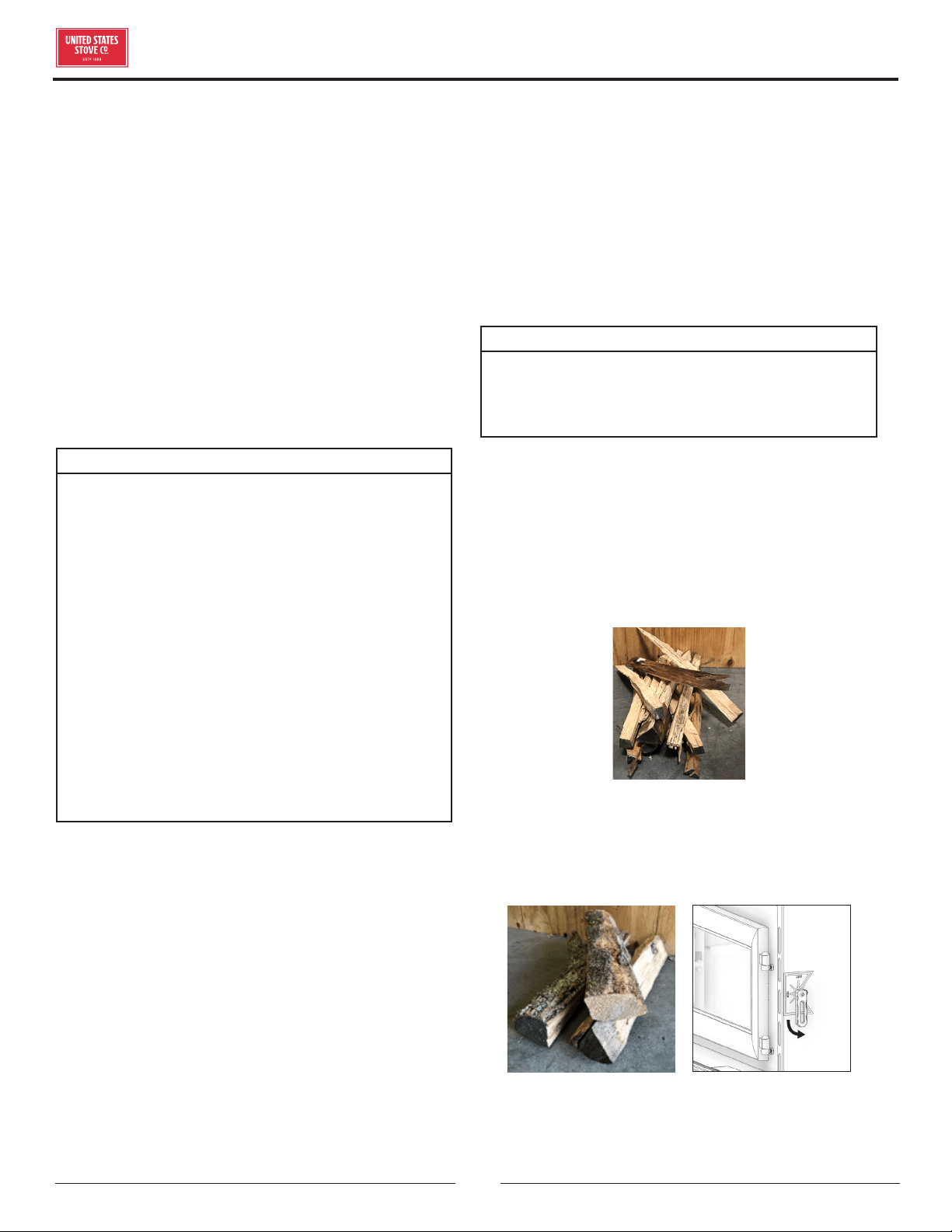
For a cold start-up, place 3 to 4 pieces of newspaper
into the firebox. On top of the newspaper, lay 2 lbs of
kindling in random placement to ensure airflow through
the kindling. On top of the kindling, place approximately 3
to 4 lbs of small pieces of cordwood. NOTE: Use smaller
pieces of wood during start-up and a high burn rate to
increase the stove temperature.
3-4 lb
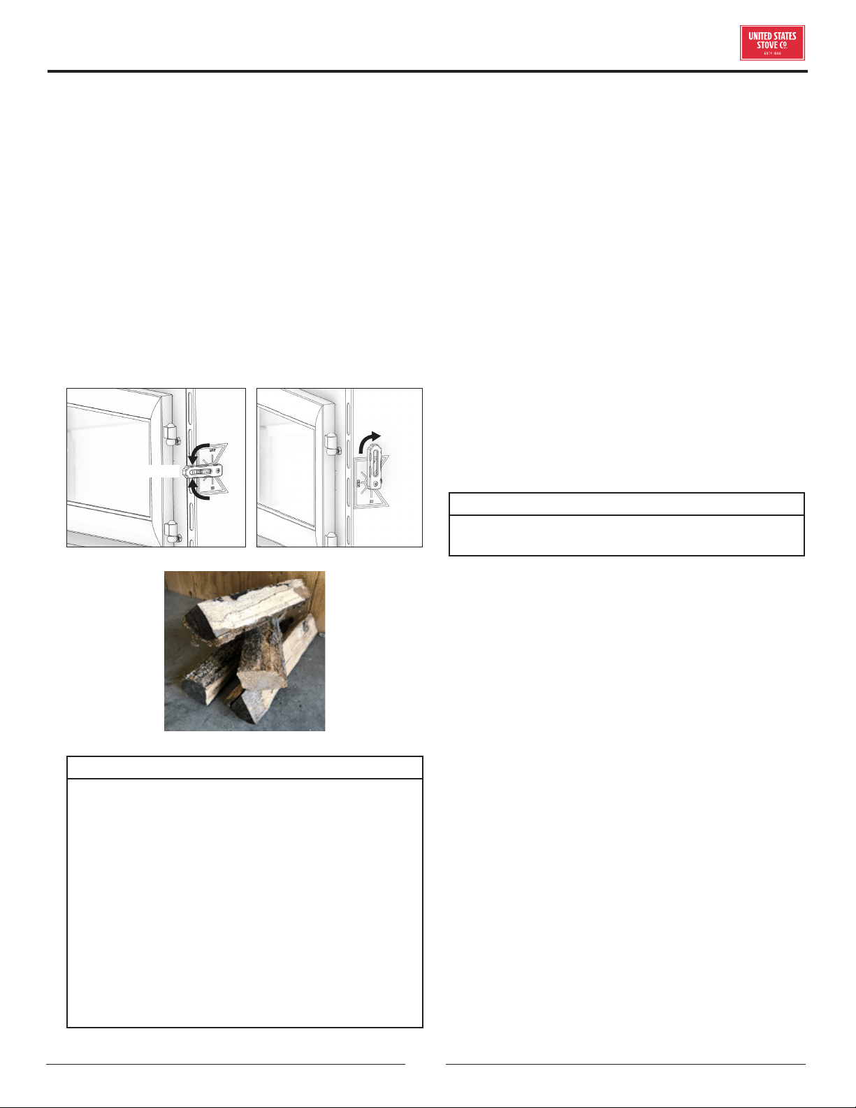
Rotate the air control fully down. Light the newspaper
and close the door. Once the kindling has burned down to
a starter coal bed, load the unit with approximately 12 to
13 lbs of fuel for the first high burn load.
HIGH
12 to 13 lbs
After the first high burn load and the stove is well warmed
up, adjust the unit as needed for a medium or low burn
setting.
OPERATION INSTRUCTIONS
© 2021 United States Stove Company
13
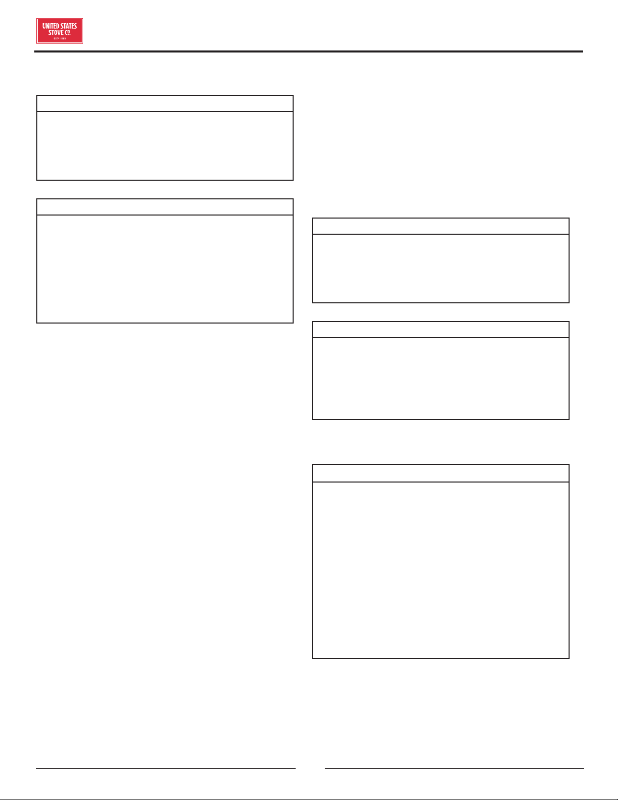
For a medium burn, once the high burn fuel load is burned
down to an established coal bed, load the unit with 14
to 15 lbs of cordwood and close the door immediately.
Leave the air control fully open (in the “HI” position) for
15 minutes. After 15 minutes rotate the air control to the
medium position (midway between the “Low” and “Hi”
position).
For a low burn setting once the high burn (or medium)
fuel load is burned down to an established coal bed, load
the unit with 14 to 15 lbs of cordwood and close the door
immediately. Leave the air control fully open (in the “HI”
position) for 15 minutes. After 15 minutes begin to rotate
the air control to the “Low” postion (air control rotated
fully up). NOTE: Do not close the air too quickly. Closing
the air too quickly will cause the unit to smoke.
MED
LOW
14 to 15 lbs
WARNINGS:
• DO NOT OVERFIRE THIS APPLIANCE.
OVERFIRING WILL OCCUR IF THE FEED DOOR
IS LEFT OPEN DURING OPERATION. IF ANY
PART OF THE APPLIANCE GLOWS, YOU ARE
OVERFIRING. ADJUST AIR CONTROLS TO A
LOWER SETTING TO SLOW DOWN THE FIRE.
• DO NOT ELEVATE THE FIRE! BUILD THE FIRE
DIRECTLY ON THE FIREBRICK. THIS APPLIANCE
HAS NOT BEEN TESTED WITH THE USE OF ANY
MEANS TO ELEVATE THE FIRE AND IT SHOULD
NOT BE ATTEMPTED.
• NEVER PUT WOOD ABOVE THE FIREBRICK
LINING OF THE FIREBOX.
VISIBLE SMOKE
The amount of visible smoke being produced can be
an eective method of determining how eciently the
combustion process is taking place in the given settings.
Visible smoke consists of unburned fuel and moisture
leaving your stove. Learn to adjust the air settings of your
specific unit to produce the smallest amount of visible
smoke. Wood that has not been seasoned properly and
has a high wood moisture content will produce excess
visible smoke and burn poorly.
AIR TUBES
The air tubes assembled in this unit are designed to
provide an accurate mix of secondary air to ensure the
highest eciency. Any damage or deterioration of these
tubes may reduce the eciency of combustion. The air
tubes are held in position by screws or snap pins. Locate
these to either side of the tube and remove it to allow the
tube to be removed and replaced.
BLOWER OPERATION
WARNING: RISK OF FIRE.
DO NOT ROUTE THE BLOWER POWER SUPPLY
CORD NEAR OR ACROSS HOT SURFACES!
The variable-speed blower circulates air warmed by the
firebox into the living area to distribute the heat more
evenly. The blower control knob is located on the side
of the blower housing. Turn the knob clockwise to turn
the blower on. The speed is controlled by turning the
knob clockwise for slower speeds and counter-clockwise
for faster speeds. To turn the blower o, turn the speed
control knob fully counter-clockwise. It is recommended
to turn the blower o when the unit is not in operation.
The blower should be removed at the beginning of every
“burn” season and air-blown clean, removing any dust or
build-up.
OPERATION INSTRUCTIONS
14
© 2021 United States Stove Company
CHIMNEY MAINTENANCE
CAUTION:
DO NOT OVERFIRE APPLIANCE. YOU ARE
OVERFIRING IF ANY PART OF THE APPLIANCE
GLOWS RED. CLOSE THE DOOR AND SHUT DAMPER
IMMEDIATELY TO REDUCE THE AIR SUPPLY AND
SLOW DOWN THE FIRE.
CAUTION:
SLOW BURNING FIRES FOR EXTENDED USE OR
BURNING GREEN WOOD MAY CAUSE EXCESSIVE
CREOSOTE BUILD-UP. IGNITION OF CREOSOTE
OR OVERFIRING COULD CAUSE A CHIMNEY
FIRE. CHIMNEY FIRES BURN EXTREMELY HOT
AND MAY IGNITE SURROUNDING COMBUSTIBLE
MATERIALS. IN CASE OF A CHIMNEY FIRE, CALL
THE FIRE DEPARTMENT IMMEDIATELY!
CREOSOTE FORMATION AND NEED FOR
REMOVAL
When wood is burned slowly, it produces tar and other
organic vapors, which combine with expelled moisture
to form creosote. The creosote vapors condense in the
relatively cool chimney flue of a slow-burning fire. As a
result, creosote residue accumulates on the flue lining.
When ignited this creosote makes an extremely high
temper fire. The chimney connector and chimney should
be inspected at least once every two months during the
heating season to determine if a creosote build-up has
occurred. If creosote has accumulated (3 mm or more),
it should be removed to reduce the risk of a chimney
fire. We strongly recommend that you install a magnetic
thermometer on your smoke exhaust pipe, approximately
18” above the stove. This thermometer will indicate the
temperature of your gas exhaust fumes within the smoke
exhaust system. The ideal temperature for these gases
is somewhere between 275°F and 500°F. Below these
temperatures, the build-up of creosote is promoted.
Above 500°F, heat is wasted since a too large quantity is
lost into the atmosphere.
TO PREVENT CREOSOTE BUILD UP
• Always burn dry wood. This allows clean burns and
higher chimney temperatures, therefore less creosote
deposit.
• Leave the air control fully open for about 5 min. every
time you reload the stove to bring it back to proper
operating temperatures. The secondary combustion
can only take place if the firebox is hot enough.
• Always check for creosote deposit once every two
months and have your chimney cleaned at least once
a year.
• If a chimney or creosote fire occurs, close all dampers
immediately. Wait for the fire to go out and the heater
to cool, then inspect the chimney for damage. If no
damage results, perform a chimney cleaning to ensure
no more creosote deposits is remaining in the chimney.
ATTENTION:
CREOSOTE OR SOOT MAY BUILD UP IN THE
CHIMNEY LINER OR CHIMNEY AND CAUSE A
HOUSE/BUILDING FIRE. INSPECT THE CHIMNEY
AND CHIMNEY LINER TWICE MONTHLY DURING
THE HEATING SEASON AND CLEAN IF NECESSARY.
CAUTION:
A CHIMNEY FIRE MAY CAUSE IGNITION OF WALL
STUDS OR RAFTERS WHICH WERE ASSUMED TO
BE A SAFE DISTANCE AWAY FROM THE CHIMNEY.
IF A CHIMNEY FIRE OCCURS, HAVE YOUR
CHIMNEY INSPECTED BY A QUALIFIED EXPERT
BEFORE USING AGAIN.
ASH REMOVAL & DISPOSAL
CAUTIONS:
• ASHES COULD CONTAIN HOT EMBERS EVEN
AFTER TWO DAYS WITHOUT OPERATING THE
STOVE.
• THE ASH PAN CAN BECOME VERY HOT. WEAR
GLOVES TO PREVENT INJURY.
• NEVER BURN THE STOVE WITH THE ASH TRAP
OPEN. THIS WOULD RESULT IN OVER FIRING
THE STOVE. DAMAGE TO THE STOVE AND EVEN
HOUSE FIRE MAY RESULT.
• ASHES SHOULD NOT BE ALLOWED TO
ACCUMULATE MORE THAN TWO TO THREE
INCHES IN THE FIREBOX.
Whenever ashes get 2 to 3 inches deep in your firebox or
ash pan, and when the fire has burned down and cooled,
remove excess ashes. Leave an ash bed approximately
1 inch deep on the firebox bottom to help maintain a
hot charcoal bed. Ashes should be placed in a metal
container with a tight-fitting lid. The closed container of
NEVER OPERATE THIS PRODUCT WHILE UNATTENDED
© 2021 United States Stove Company
15
CHIMNEY MAINTENANCE
ashes should be placed on a non-combustible floor or the
ground, away from all combustible materials, pending
final disposal. The ashes should be retained in the closed
container until all cinders have thoroughly cooled.
SMOKE & CO MONITORS
Burning wood naturally produces smoke and carbon
monoxide(CO) emissions. CO is a poisonous gas when
exposed to elevated concentrations for extended
periods. While the modern combustion systems in
heaters drastically reduce the amount of CO emitted
out the chimney, exposure to the gases in closed or
confined areas can be dangerous. Make sure your stove
gaskets and chimney joints are in good working order
and sealing properly to ensure unintended exposure. It is
recommended that you use both smoke and CO monitors
in areas having the potential to generate CO.
GLASS CARE
• Inspect and clean the glass regularly to detect any
cracks. If you spot one, turn the stove o immediately.
Do not abuse the glass door by striking or slamming
shut. Do not use the stove if the glass is broken.
• If the glass on your stove breaks, replace only with
the glass supplied from your heater dealer. Never
substitute other materials for the glass.
• To replace the glass, remove the screws retaining the
glass moldings inside the door. Remove the moldings
and replace the damaged piece with a new one.
Perform the procedure backward after replacing it.
When replacing the glass, you should change the glass
gasket to make sure you keep it sealed.
• Never wash the glass with a product that may scratch.
Use a specialized product, available in the stores where
wood stoves are sold. The glass should be washed only
when cold.
GASKET CARE
WARNING:
NEVER OPERATE THE STOVE WITHOUT A GASKET
OR WITH A BROKEN ONE. DAMAGE TO THE STOVE
OR EVEN HOUSE FIRE MAY RESULT.
This unit’s door uses a 1” diameter rope gasket. It is
recommended that you change the door gasket (which
makes your stove door air tight) once a year, in order
to ensure good control over the combustion, maximum
eciency and security. To change the door gasket, simply
remove the damaged one. Carefully clean the available
gasket groove, apply a high temperature silicone sold for
this purpose, and install the new gasket. You may light
up your stove again approximately 24 hours after having
completed this operation.
ATTENTION:
THIS WOOD HEATER NEEDS PERIODIC INSPECTION
AND REPAIR FOR PROPER OPERATION. IT IS
AGAINST FEDERAL REGULATIONS TO OPERATE
THIS WOOD HEATER IN A MANNER INCONSISTENT
WITH OPERATING INSTRUCTIONS IN THIS
MANUAL.
REMOVING THE INSERT FOR PURPOSE OF
INSPECTION
ATTENTION:
FIREPLACE INSERT SURROUND PANELS MAY BE
REMOVED TO INSPECT FIREPLACE INSERT AND
FIREPLACE.
1. If for any reason you must remove the insert for
inspection of the appliance or fireplace, follow these
rules.
2. Ensure appliance is not in operation and is thoroughly
cooled.
3. Remove the surround by removing the springs
retaining it to the appliance.
4. Disconnect the flue gas pipe from the appliance.
5. Slide appliance out to perform inspection.
16
© 2021 United States Stove Company
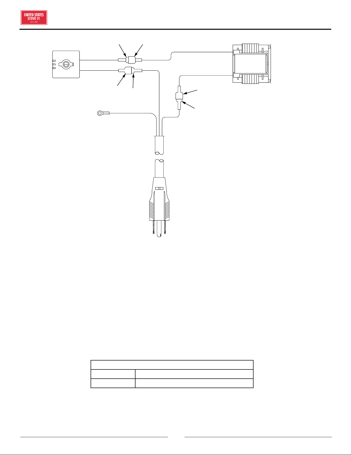
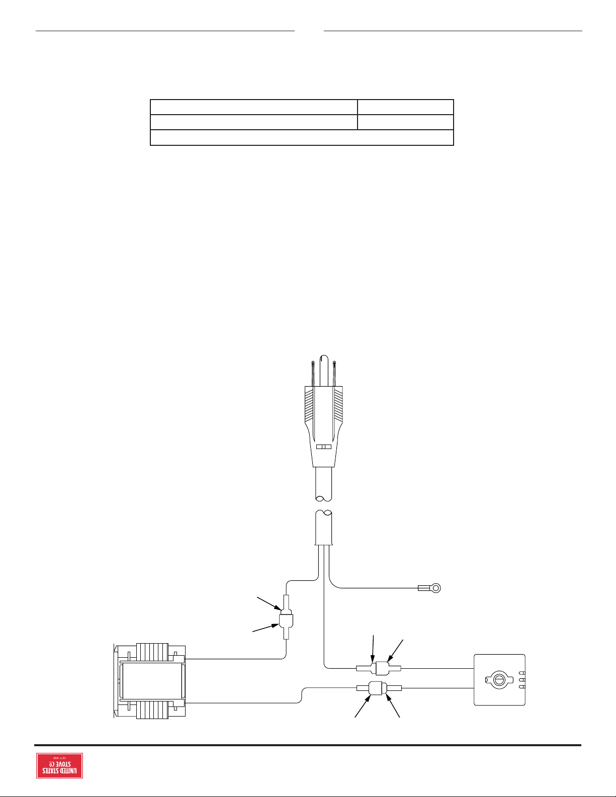
FEMALE
FEMALE
FEMALE
GREEN
WARNING! DO
NOT ROUTE THE
SUPPLY CORD
NEAR OR ACROSS
HOT SURFACES!
CAUTION!
THE BLOWER ASSEMBLY
MUST BE DISCONNECTED
FROM THE SOURCE OF
ELECTRICAL SUPPLY
BEFORE ATTEMPTING ANY
MAINTENANCE.
MALE
BLACK
BLACK
BLACK
WHITE
BLACK
WHITE
MALE
BLOWER
MOTOR
SUPPLY CORD
BLOWER
RHEOSTAT
ATTACH TO BACK OF
BLOWER HOUSING
MALE
WIRING DIAGRAM
For Parts Assistance Call: 800-750-2723 Ext 5051 or Email: parts@usstove.com
The information in this owner’s manual is specific to your unit. When ordering replacement parts the information
in this manual will help to ensure the correct items are ordered. Before contacting customer service write down the
model number and the serial number of this unit. That information can be found on the certification label attached
to the back of the unit. Other information that may be needed would be the part number and part description of the
item(s) in question. Part numbers and descriptions can be found in the “Repair Parts” section of this manual. Once
this information has been gathered you can contact customer service by phone 1-800-750-2723 Ext 5051 or Email
parts@usstove.com.
Model Information
Model Number
Serial Number
HOW TO ORDER REPAIR PARTS
© 2021 United States Stove Company
17
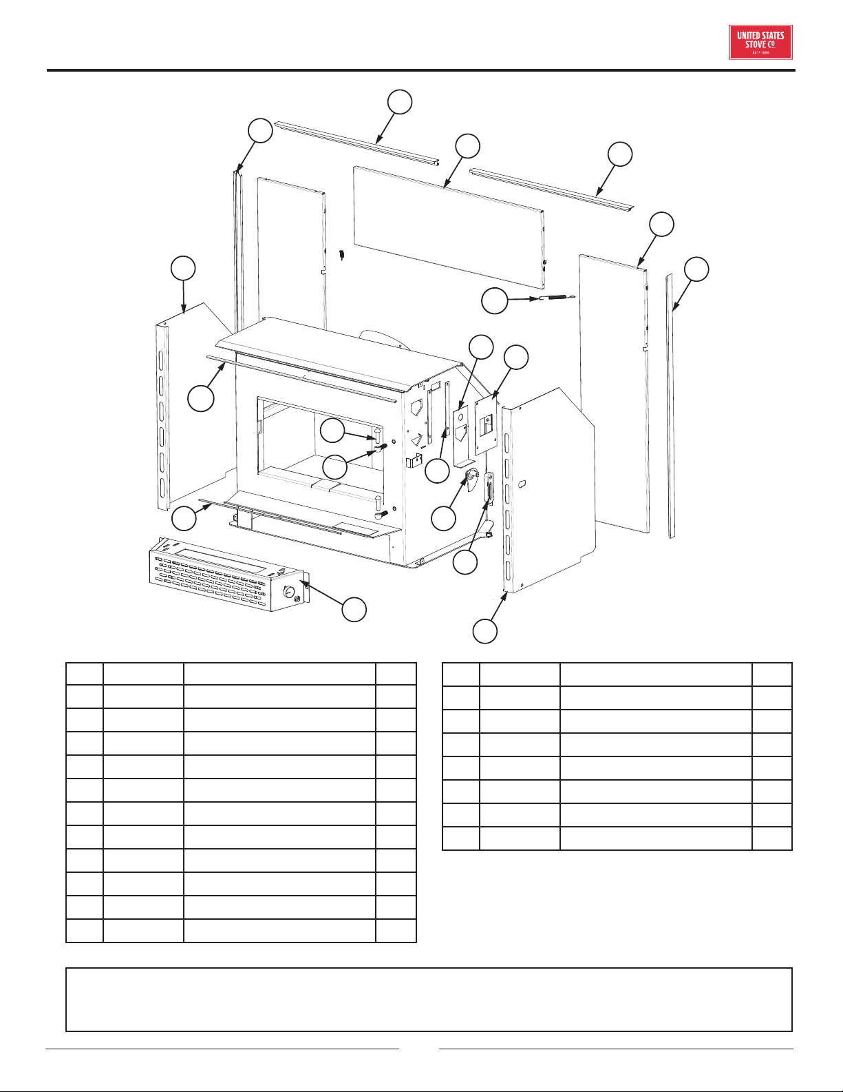
REPAIR PARTS
Key Part # Description Qty
1 892176 Top Trim 1
2 892177 Hearth Plate Trim 1
3 80857 Assembly, Blower 1
4 611008 Right Cabinet 1
5 893261 Damper Slide 1
6 29301 Slide Brace 2
7 893261 Wood Handle 1
8 29300 Cover 1
9 29298 Damper 1
10 611007 Left Cabinet 1
11 892294 Hinge Pin 2
12 40571 Hinge Block 2
13 83913 Extension Spring 2
14 26269 Top Surround 1
15 26270 Side Surround 2
16 891992-1 Surround Trim-R 1
17 891992-2 Surround Trim-L 1
18 891992-3 Surround Top Trim-L 1
19 891992-4 Surround Top Trim-R 1
10
1
13
8
15
16
18
19
17
14
9
7
4
5
6
2
3
12
11
IN ORDER TO MAINTAIN WARRANTY, COMPONENTS MUST BE REPLACED USING ORIGINAL
MANUFACTURERS PARTS PURCHASED THROUGH YOUR DEALER OR DIRECTLY FROM THE APPLIANCE
MANUFACTURER. USE OF THIRD PARTY COMPONENTS WILL VOID THE WARRANTY.
To order parts:
Call 1-800-750-2723 Ext 5051 or
Email to: parts@usstove.com
18
© 2021 United States Stove Company
IN ORDER TO MAINTAIN WARRANTY, COMPONENTS MUST BE REPLACED USING ORIGINAL
MANUFACTURERS PARTS PURCHASED THROUGH YOUR DEALER OR DIRECTLY FROM THE APPLIANCE
MANUFACTURER. USE OF THIRD PARTY COMPONENTS WILL VOID THE WARRANTY.
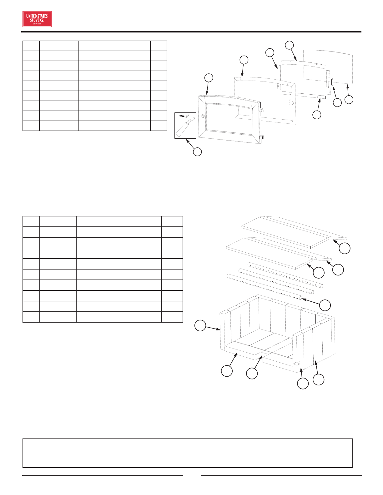
Key Part # Description Qty
1 891414 Half Firebrick 2
2 89066 Firebrick (4-1/2 x 9) 9
3 891989-2 Firebrick (1-1/4 x 2-1/4) 1
4 893010 Half Firebrick (Notched) 1
5 891989-1 Firebrick (3.33 x 9) 8
6 86963 Secondary Tube 3
7 88158 Ceramic Fiber Board (Front) 1
8 88159 Ceramic Fiber Board (Rear) 1
9 88160 Blanket Insulation 1
3
2
5
4
1
6
8
9
7
REPAIR PARTS
To order parts:
Call 1-800-750-2723 Ext 5051 or
Email to: parts@usstove.com
To order parts:
Call 1-800-750-2723 Ext 5051 or
Email to: parts@usstove.com
Key Part # Description Qty
1 893241-US Complete Door Handle 1
2 40887 Medium Arched Door 1
3 88324 1” Rope Gasket 1
4 29229 Side Glass Retainers 2
5 29227 Top Glass Retainer 1
6 893159 Clear Glass 1
7 29230 Gasket Clamp 1
8 29228 Bottom Glass Retainer 1
1
2
3
4
8
7
5
6
© 2021 United States Stove Company
19
It is recommended that your heating system is serviced regularly and that the appropriate Service Interval Record is
completed.
SERVICE PROVIDER
Before completing the appropriate Service Record below, please ensure you have carried out the service as described in
the manufacturer’s instructions. Always use the manufacturer's specified spare part when replacement is necessary.
Service 01 Date: ______________________
Engineer Name: ____________________________________
License No.: ________________________________________
Company: __________________________________________
Telephone No.: _____________________________________
Stove Inspected:
Chimney Swept:
Items Replaced: ____________________________________
Service 03 Date: ______________________
Engineer Name: ____________________________________
License No.: ________________________________________
Company: __________________________________________
Telephone No.: _____________________________________
Stove Inspected:
Chimney Swept:
Items Replaced: ____________________________________
Service 05 Date: ______________________
Engineer Name: ____________________________________
License No.: ________________________________________
Company: __________________________________________
Telephone No.: _____________________________________
Stove Inspected:
Chimney Swept:
Items Replaced: ____________________________________
Service 07 Date: ______________________
Engineer Name: ____________________________________
License No.: ________________________________________
Company: __________________________________________
Telephone No.: _____________________________________
Stove Inspected:
Chimney Swept:
Items Replaced: ____________________________________
Service 02 Date: ______________________
Engineer Name: ____________________________________
License No.: ________________________________________
Company: __________________________________________
Telephone No.: _____________________________________
Stove Inspected:
Chimney Swept:
Items Replaced: ____________________________________
Service 04 Date: ______________________
Engineer Name: ____________________________________
License No.: ________________________________________
Company: __________________________________________
Telephone No.: _____________________________________
Stove Inspected:
Chimney Swept:
Items Replaced: ____________________________________
Service 06 Date: ______________________
Engineer Name: ____________________________________
License No.: ________________________________________
Company: __________________________________________
Telephone No.: _____________________________________
Stove Inspected:
Chimney Swept:
Items Replaced: ____________________________________
Service 08 Date: ______________________
Engineer Name: ____________________________________
License No.: ________________________________________
Company: __________________________________________
Telephone No.: _____________________________________
Stove Inspected:
Chimney Swept:
Items Replaced: ____________________________________
SERVICE RECORD

20
© 2021 United States Stove Company
NOTES
20
© 2021 United States Stove Company
Il est recommandé que votre système de chauage est desservi régulièrement et que le Service Interval enregistrement approprié
est terminée.
FOURNISSEUR DE SERVICES
Avant de terminer l’enregistrement de service approprié ci-dessous, s’il vous plaît vous assurer que vous avez eectué le service tel
que décrit dans le les instructions du fabricant. Toujours utiliser pièce de rechange indiquée par le fabricant lors de remplacement
est nécessaire.
Service de 01 Date: ______________________
Nom de l’ingénieur: _________________________________
N° de licence.: ______________________________________
Compagnie: ________________________________________
N° de téléphone: ___________________________________
Poêle Inspecté:
Cheminée balayée:
Articles Remplacé: _________________________________
Service de 03 Date: ______________________
Nom de l’ingénieur: _________________________________
N° de licence.: ______________________________________
Compagnie: ________________________________________
N° de téléphone: ___________________________________
Poêle Inspecté:
Cheminée balayée:
Articles Remplacé: _________________________________
Service de 05 Date: ______________________
Nom de l’ingénieur: _________________________________
N° de licence.: ______________________________________
Compagnie: ________________________________________
N° de téléphone: ___________________________________
Poêle Inspecté:
Cheminée balayée:
Articles Remplacé: _________________________________
Service de 07 Date: ______________________
Nom de l’ingénieur: _________________________________
N° de licence.: ______________________________________
Compagnie: ________________________________________
N° de téléphone: ___________________________________
Poêle Inspecté:
Cheminée balayée:
Articles Remplacé: _________________________________
Service de 02 Date: ______________________
Nom de l’ingénieur: _________________________________
N° de licence.: ______________________________________
Compagnie: ________________________________________
N° de téléphone: ___________________________________
Poêle Inspecté:
Cheminée balayée:
Articles Remplacé: _________________________________
Service de 04 Date: ______________________
Nom de l’ingénieur: _________________________________
N° de licence.: ______________________________________
Compagnie: ________________________________________
N° de téléphone: ___________________________________
Poêle Inspecté:
Cheminée balayée:
Articles Remplacé: _________________________________
Service de 06 Date: ______________________
Nom de l’ingénieur: _________________________________
N° de licence.: ______________________________________
Compagnie: ________________________________________
N° de téléphone: ___________________________________
Poêle Inspecté:
Cheminée balayée:
Articles Remplacé: _________________________________
Service de 08 Date: ______________________
Nom de l’ingénieur: _________________________________
N° de licence.: ______________________________________
Compagnie: ________________________________________
N° de téléphone: ___________________________________
Poêle Inspecté:
Cheminée balayée:
Articles Remplacé: _________________________________
ENREGISTREMENT DE SERVICE
© 2021 United States Stove Company
19
AFIN DE MAINTENIR LA GARANTIE, LES COMPOSANTS DOIVENT ÊTRE REMPLACÉS PAR DES PIÈCES D’ORIGINE
ACHETÉES CHEZ VOTRE REVENDEUR OU DIRECTEMENT AUPRÈS DU FABRICANT DE L’APPAREIL. L’UTILISATION DE
COMPOSANTS TIERS ANNULERA LA GARANTIE.
PIÈCES DE RECHANGE
Clé Partie # Description Qté
1 891414 Demi-brique réfractaire 2
2 89066 Brique réfractaire (4-1 / 2 x 9) 9
3 891989-2 Brique réfractaire (1-1 / 4 x 2-1 / 4) 1
4 893010 Demi-brique réfractaire (entaillé) 1
5 891989-1 Brique réfractaire (3,33 x 9) 8
6 86963 Tube secondaire 3
7 88158 Panneau en fibre de céramique (avant) 1
8 88159 Panneau en fibre de céramique (arrière) 1
9 88160 Isolation de couverture 1
3
2
5
4
1
6
8
9
7
Pour commander des pièces:
Appelez le 1-800-750-2723 Ext 5051 ou
Envoyez un courriel à: parts@usstove.com
Pour commander des pièces:
Appelez le 1-800-750-2723 Ext 5051 ou
Envoyez un courriel à: parts@usstove.com
Clé Partie # Description Qté
1 893241-US
Poignée de porte
complète
1
2 40887 Porte cintrée moyenne 1
3 88324 Joint de corde de 1 po 1
4 29229
Retenues de verre
latérales
2
5 29227
Support de verre
supérieur
1
6 893159 Verre propre 1
7 29230 Collier de serrage 1
8 29228 Support de verre inférieur 1
1
2
3
4
8
7
5
6
18
© 2021 United States Stove Company
AFIN DE MAINTENIR LA GARANTIE, LES COMPOSANTS DOIVENT ÊTRE REMPLACÉS PAR DES PIÈCES D’ORIGINE
ACHETÉES CHEZ VOTRE REVENDEUR OU DIRECTEMENT AUPRÈS DU FABRICANT DE L’APPAREIL. L’UTILISATION DE
COMPOSANTS TIERS ANNULERA LA GARANTIE.
PIÈCES DE RECHANGE
Clé Partie # Description Qté
1 892176 Garniture supérieure 1
2 892177 Garniture de plaque de foyer 1
3 80857 Assemblage, ventilateur 1
4 611008 Cabinet droit 1
5 893261 Glissière d'amortisseur 1
6 29301 Accolade coulissante 2
7 893261 Manche en bois 1
8 29300 Couverture 1
9 29298 Amortisseur 1
10 611007 Cabinet gauche 1
11 892294 Axe De Charnière 2
12 40571 Bloc De Charnière 2
13 83913 ressort d'extension 2
14 26269 contour supérieur 1
15 26270 bordure latérale 2
16 891992-1 bordure intérieure droite 1
17 891992-2 bordure intérieure gauche 1
18 891992-3 bordure supérieure gauche 1
19 891992-4
entourer la garniture supérieure
droite
1
10
1
13
8
15
16
18
19
17
14
9
7
4
5
6
2
3
12
11
Pour commander des pièces:
Appelez le 1-800-750-2723 Ext 5051 ou
Envoyez un courriel à: parts@usstove.com
© 2021 United States Stove Company
17
SCHÉMA DE CÂBLAGE
Femme
Femme
Femme
Vert
Attention! Ne faites
pas passer le cordon
d’alimentation à
proximité ou sur des
surfaces chaudes
Mise en garde! Le
ventilateur doit être
déconnecté de la source
d’alimentation électrique
avant de tenter toute
opération de maintenance.
Mâle
Noire
Noire
Noire
Blanche
Noire
Blanche
Mâle
Moteur de la
souante
Cordon d’alimentation
Rhéostat
soueur
Fixation au boîtier du
ventilateur
Mâle
COMMANDE DE PIÈCES DE RECHANGE
Les informations contenues dans ce manuel du propriétaire sont spécifiques à votre appareil. Lors de la commande de pièces de
rechange, les informations contenues dans ce manuel vous aideront à vous assurer que les bons articles sont commandés. Avant
de contacter le service client, notez le numéro de modèle et le numéro de série de cet appareil. Cette information se trouve sur
l’étiquette de certification apposée à l’arrière de l’appareil. D’autres informations qui pourraient être nécessaires sont le numéro de
pièce et la description de l’article en question. Les références et les descriptions se trouvent dans la section «Pièces de réparation»
de ce manuel. Une fois ces informations recueillies, vous pouvez contacter le service client par téléphone au 1-800-750-2723,
poste 5051 ou par e-mail à parts@usstove.com.
Informations sur le modèle
Numéro de modèle
Numéro de série
POUR L’ASSISTANCE SUR LES PIÈCES, APPELEZ LE 8007502723, POSTE 5051 OU PAR
COURRIEL: PARTSUSSTOVE.COM
16
© 2021 United States Stove Company
AVERTISSEMENT:
• LES CENDRES POURRAIENT CONTENIR DES
EMBRES CHAUDS MÊME APRÈS DEUX JOURS SANS
FONCTIONNER LE POÊLE.
• LE CENDRIER PEUT DEVENIR TRÈS CHAUD. PORTEZ
DES GANTS POUR ÉVITER LES BLESSURES.
• NE JAMAIS BRÛLER LE POÊLE AVEC LE TRAPPE À
CENDRES OUVERT. CELA POURRAIT ENTRAÎNER
UNE SURCHAUFFE DU POÊLE. DES DOMMAGES
AU POÊLE ET MÊME UN INCENDIE PEUVENT EN
RÉSULTER.
• LES CENDRES NE DOIVENT PAS ÊTRE AUTORISÉES À
ACCUMULER PLUS DE DEUX À TROIS POUCES DANS
LA BOÎTE À FEU.
DÉTECTEURS DE FUMÉE ET DE CO
Le brûlage du bois produit naturellement des émissions
de fumée et du monoxyde de carbone (CO). Le CO est un
gaz poison lorsque l’exposition se fait à des concentrations
élevées pour une période de temps prolongée. Bien que les
systèmes de combustion modernes des chauages réduisent
de façon importante la quantité de CO émis par la cheminée,
l’exposition aux gaz dans des endroits fermés ou clos peut être
dangereuse. Assurez-vous que les joints d’étanchéité de votre
poêle et les joints de la cheminée soient en bon état et qu’ils
scellent correctement, évitant les expositions indésirables. Il
est recommandé que vous utilisiez des détecteurs de fumée et
de CO dans les zones où se trouve un potentiel de génération
de CO.
ENTRETIEN VERRE
• Inspectez et nettoyez régulièrement la vitre pour détecter
d’éventuelles fissures. Si vous en repérez, éteignez
immédiatement le poêle. N’abusez pas de la porte vitrée en
la claquant ou en la claquant. N’utilisez pas le poêle si le verre
est cassé.
• Si le verre de votre poêle se brise, remplacez-le uniquement
par le verre fourni par votre revendeur de chauage. Ne
remplacez jamais d’autres matériaux par le verre.
• Pour remplacer la vitre, retirez les vis retenant les moulures
en verre à l’intérieur de la porte. Retirez les moulures et
remplacez la pièce endommagée par une nouvelle. Eectuez
la procédure à l’envers après l’avoir remplacé. Lors du
remplacement de la vitre, vous devez changer le joint en verre
pour vous assurer de le garder scellé.
• Ne lavez jamais la vitre avec un produit qui pourrait rayer.
Utilisez un produit spécialisé, disponible dans les magasins
où les poêles à bois sont vendus. Le verre ne doit être lavé
qu’à froid.
ENTRETIEN DES JOINT
AVERTISSEMENT:
NE JAMAIS FAIRE FONCTIONNER LE POÊLE SANS JOINT
D’ÉTANCHÉITÉ OU AVEC UN CASSÉ. DES DOMMAGES
AU POÊLE OU MÊME UN INCENDIE PEUVENT EN
RÉSULTER.
La porte de cet appareil utilise un joint de corde de 1 po de
diamètre. Il est recommandé de changer le joint de porte (qui
rend la porte de votre poêle étanche à l’air) une fois par an, afin
d’assurer un bon contrôle de la combustion, une ecacité et
une sécurité maximales. Pour changer le joint de porte, retirez
simplement celui qui est endommagé. Nettoyez soigneusement
la rainure du joint disponible, appliquez un silicone haute
température vendu à cet eet et installez le nouveau joint.
Vous pouvez rallumer votre poêle environ 24 heures après avoir
terminé cette opération.
AVERTISSEMENT:
CE CHAUFFE-BOIS A BESOIN D’INSPECTION
ET DE RÉPARATION PÉRIODIQUES POUR UN
FONCTIONNEMENT APPROPRIÉ. IL EST CONTRE LES
RÈGLEMENTS FÉDÉRAUX DE FAIRE FONCTIONNER CE
CHAUFFE-BOIS D’UNE MANIÈRE INCOMPATIBLE AVEC
LES INSTRUCTIONS D’UTILISATION DE CE MANUEL.
RETRAIT DE L’INSERT À DES FINS
D’INSPECTION
ATTENTION:
LES PANNEAUX ENVIRONNANTS DE L'INSERT DU
FOYER PEUVENT ÊTRE RETIRÉS POUR INSPECTER
L'INSERT ET LE FOYER.
1. Si, pour une raison quelconque, vous devez retirer
l’encastrable pour l’inspection de l’appareil ou du foyer,
suivez ces règles.
2. Assurez-vous que l’appareil n’est pas en marche et est
complètement refroidi.
3. Retirez le contour en retirant les ressorts qui le retiennent
à l’appareil.
4. Débranchez le tuyau de gaz de combustion de l’appareil.
5. Faites glisser l’appareil pour eectuer l’inspection
ENTRETIEN DE LA CHEMINÉE
© 2021 United States Stove Company
15
ENTRETIEN DE LA CHEMINÉE
AVERTISSEMENT:
NE PAS SURCHARGER L’APPAREIL. VOUS SURFIRMEZ
SI UNE PIÈCE DE L’APPAREIL EST ROUGE. FERMER LA
PORTE ET FERMER IMMÉDIATEMENT LE VOLET POUR
RÉDUIRE L’ALIMENTATION EN AIR ET RALENTIR LE FEU.
AVERTISSEMENT:
LES FEUX LENTS POUR UNE UTILISATION PROLONGÉE
OU LA BRÛLURE DU BOIS VERT PEUVENT CAUSER
UNE ACCUMULATION EXCESSIVE DE CRÉOSOTE.
L’ALLUMAGE DE CRÉOSOTE OU LA SURCHAUFFE
POURRAIT CAUSER UN INCENDIE DE CHEMINÉE. LES
FEUX DE CHEMINÉE BRÛLENT EXTRÊMEMENT CHAUD
ET PEUVENT ALLUMER LES MATIÈRES COMBUSTIBLES
ENVIRONNANTES. EN CAS D’INCENDIE DE CHEMINÉE,
APPELEZ IMMÉDIATEMENT LE SERVICE DES
INCENDIES!
FORMATION DE CRÉOSOTE ET BESOIN
D’ENLÈVEMENT
Lorsque le bois est brûlé lentement, il produit du goudron et
d’autres vapeurs organiques, qui se combinent avec l’humidité
expulsée pour former de la créosote. Les vapeurs de créosote
se condensent dans le conduit de cheminée relativement frais
d’un feu à combustion lente. Par conséquent, des résidus de
créosote s’accumulent sur le revêtement du conduit de fumée.
Lorsqu’elle est allumée, cette créosote fait un feu extrêmement
élevé. Le raccord de cheminée et la cheminée doivent être
inspectés au moins une fois tous les deux mois pendant la
saison de chauage pour déterminer si une accumulation de
créosote s’est produite. Si la créosote s’est accumulée (3 mm
ou plus), elle doit être retirée pour réduire le risque d’incendie
de cheminée. Nous vous recommandons fortement d’installer
un thermomètre magnétique sur votre tuyau d’échappement
de fumée, à environ 18 po au-dessus du poêle. Ce thermomètre
indiquera la température de vos fumées d’échappement de
gaz dans le système d’évacuation des fumées. La température
idéale pour ces gaz se situe entre 275°F et 500°F. En dessous
de ces températures, l’accumulation de créosote est favorisée.
Au-dessus de 500°F, la chaleur est perdue car une trop grande
quantité est perdue dans l’atmosphère.
POUR ÉVITER LA CONSTRUCTION DE
CRÉOSOTE
• Brûlez toujours du bois sec. Cela permet des brûlures propres
et des températures de cheminée plus élevées, donc moins
de dépôt de créosote.
• Laissez le contrôle d’air complètement ouvert pendant
environ 5 min. chaque fois que vous rechargez le poêle pour le
ramener à des températures de fonctionnement appropriées.
La combustion secondaire ne peut avoir lieu que si le foyer est
susamment chaud.
• Vérifiez toujours le dépôt de créosote une fois tous les deux
mois et faites nettoyer votre cheminée au moins une fois par
an.
• En cas d’incendie de cheminée ou de créosote, fermez
immédiatement tous les registres. Attendez que le feu
s’éteigne et que le chaue-eau refroidisse, puis inspectez la
cheminée pour déceler tout dommage. Si aucun dommage
ne se produit, eectuez un nettoyage de cheminée pour vous
assurer qu’il ne reste plus de dépôts de créosote dans la
cheminée.
AVERTISSEMENT:
DE LA CRÉOSOTE OU DE LA SUIE PEUVENT
S’ACCUMULER DANS LA DOUBLURE DE CHEMINÉE
OU LA CHEMINÉE ET CAUSER UN INCENDIE DANS LA
MAISON / IMMEUBLE. INSPECTER LA CHEMINÉE ET
LA DOUBLURE DE CHEMINÉE DEUX FOIS PAR MOIS
PENDANT LA SAISON DE CHAUFFAGE ET NETTOYER SI
NÉCESSAIRE.
AVERTISSEMENT:
UN FEU DE CHEMINÉE PEUT CAUSER L’ALLUMAGE
DE GOUJONS MURAUX OU DE RAFTERS QUI ONT ÉTÉ
PRÉPOSÉS ÊTRE À UNE DISTANCE SÉCURITAIRE DE
LA CHEMINÉE. EN CAS D’INCENDIE DE CHEMINÉE,
FAITES INSPECTER VOTRE CHEMINÉE PAR UN EXPERT
QUALIFIÉ AVANT DE L’UTILISER À NOUVEAU.
ENLÈVEMENT DES CENDRES ET LEUR
DISPOSITION
Chaque fois que les cendres atteignent 3 à 4 pouces de
profondeur dans votre foyer ou cendrier, et lorsque le feu a brûlé
et refroidi, retirez les cendres en excès. Laissez un lit de cendres
d’environ 1 pouce de profondeur sur le fond de la chambre de
combustion pour aider à maintenir un lit de charbon de bois
chaud. Les cendres doivent être placées dans un récipient en
métal avec un couvercle hermétique. Le contenant fermé de
cendres doit être placé sur un sol incombustible ou sur le sol, à
l’écart de tout matériau combustible, en attendant l’élimination
finale. Les cendres doivent être conservées dans le récipient
fermé jusqu’à ce que toutes les cendres aient complètement
refroidi.
NE JAMAIS UTILISER CE PRODUIT SANS SURVEILLANCE
14
© 2021 United States Stove Company
INSTRUCTIONS D’UTILISATION DU BOIS
MISES EN GARDE:
• NE SURCHAUFFEZ PAS CET APPAREIL. UNE
SURCHAUFFE SE PRODUIT SI LA PORTE
D'ALIMENTATION EST LAISSÉE OUVERTE PENDANT
LE FONCTIONNEMENT. SI UNE PIÈCE DE L'APPAREIL
BRILLENT, VOUS SURCHARGEZ. RÉGLEZ LES
COMMANDES D'AIR À UN RÉGLAGE INFÉRIEUR POUR
RALENTIR LE FEU.
• N'ÉLEVEZ PAS LE FEU! CONSTRUISEZ LE FEU
DIRECTEMENT SUR LA BRIQUE. CET APPAREIL
N'A PAS ÉTÉ TESTÉ AVEC L'UTILISATION D'AUCUN
MOYEN POUR ÉLEVER LE FEU ET IL NE DOIT PAS
ÊTRE TENTÉ.
• NE JAMAIS METTRE DE BOIS AU-DESSUS DE LA
GARNITURE FIREBRICK DE LA FIREBOX.
FUMÉE VISIBLE
La quantité de fumée visible produite peut être une méthode
ecace pour déterminer l’ecacité du processus de combustion
aux paramètres donnés. La fumée visible est constituée de
combustible non brûlé et d’humidité sortant de votre poêle.
Apprenez à régler les paramètres d’air de votre unité spécifique
pour produire la plus petite quantité de fumée visible. Le bois
qui n’a pas été correctement séché et qui a une teneur élevée
en humidité produira un excès de fumée visible et brûlera mal.
CONDUITS D’AIR
Les conduits d’air assemblés dans cette unité sont conçus
pour orir un mélange précis d’air secondaire et assurer une
plus grande ecacité. Tout dommage ou détérioration de ces
conduits peuvent réduire l’ecacité de la combustion. Les
conduits d’air sont maintenus en position par des vis ou par des
goupilles de blocage. Localisez et enlevez-les des deux côtés du
conduit pour le retirer et le remettre en place.
FONCTIONNEMENT DE LA SOUFFLERIE
AVERTISSEMENT: RISQUE D'INCENDIE.
NE PAS RACCORDER LE CORDON D'ALIMENTATION
DU SOUFFLEUR À PROXIMITÉ OU À TRAVERS DES
SURFACES CHAUDES!
Le ventilateur à vitesse variable fait circuler l’air réchaué par
la chambre de combustion dans le salon pour répartir la chaleur
plus uniformément. Le bouton de commande du ventilateur est
situé sur le côté du boîtier du ventilateur. Tournez le bouton dans
le sens des aiguilles d’une montre pour mettre le ventilateur en
marche. La vitesse est contrôlée en tournant le bouton dans le
sens des aiguilles d’une montre pour des vitesses plus lentes
et dans le sens inverse des aiguilles d’une montre pour des
vitesses plus rapides. Pour arrêter le ventilateur, tournez le
bouton de commande de vitesse à fond dans le sens antihoraire.
Il est recommandé d’éteindre le ventilateur lorsque l’unité n’est
pas en fonctionnement. Le ventilateur doit être retiré au début
de chaque saison de «brûlure» et nettoyé par soufflage à l’air,
en éliminant toute poussière ou accumulation.
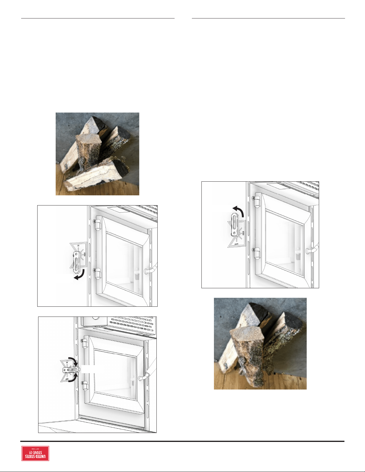
© 2021 United States Stove Company
13
INSTRUCTIONS D’UTILISATION DU BOIS
Tournez complètement le contrôle d’air vers le bas. Allumez le
journal et fermez la porte. Une fois que le bois d’allumage a brûlé
jusqu’à un lit de charbon de démarrage, chargez l’unité d’environ
12 à 13 lb de carburant pour la première charge de combustion
élevée.
12 à 13 lb
HIGH
HAUTE
Après la première charge de combustion élevée et le poêle est
bien réchaué, ajustez l’unité au besoin pour un réglage de
combustion moyen ou faible.
Pour une combustion moyenne, une fois que la charge de
combustible à combustion élevée est brûlée jusqu’à un lit de
charbon établi, chargez l’unité avec 14 à 15 lb de bois de corde
et fermez immédiatement la porte. Laissez la commande d’air
complètement ouverte (en position «HI») pendant 15 minutes.
Après 15 minutes, tournez la commande pneumatique en
position moyenne (à mi-chemin entre les positions «Low» et
«Hi»).
Pour un réglage de combustion faible une fois que la charge
de combustible à combustion élevée (ou moyenne) est brûlée
jusqu’à un lit de charbon établi, chargez l’unité avec 14 à 15 lb
de bois de corde et fermez immédiatement la porte. Laissez
la commande d’air complètement ouverte (en position «HI»)
pendant 15 minutes. Après 15 minutes, commencez à faire
tourner la commande pneumatique en position «Bas» (la
commande pneumatique est entièrement tournée vers le haut).
REMARQUE: ne fermez pas l’air trop rapidement.
MED
MOYEN
LOW
FAIBLE
14 à 15 lb
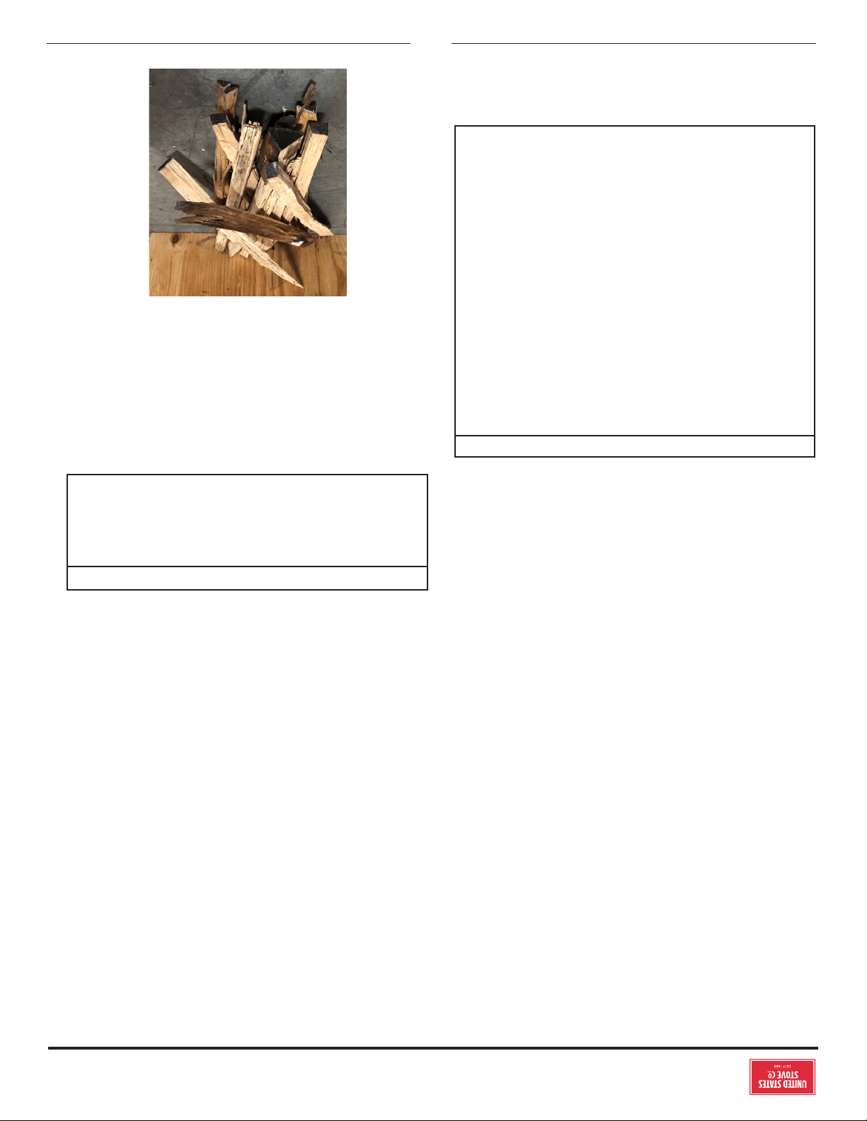
12
© 2021 United States Stove Company
INSTRUCTIONS D’UTILISATION DU BOIS
du combustible. La valeur calorifique inférieure est lorsque
l’eau quitte le processus de combustion sous forme de
vapeur, dans le cas des poêles à bois, l’humidité du bois brûlé
quitte le poêle sous forme de vapeur. Le pouvoir calorifique
supérieur est lorsque l’eau quitte le processus de combustion
complètement condensée. Dans le cas des poêles à bois, cela
supposerait que les gaz d’échappement sont à température
ambiante à la sortie du système, et donc les calculs utilisant
cette valeur de chauage considèrent la chaleur qui monte
dans la cheminée comme une énergie perdue. Par conséquent,
l’ecacité calculée en utilisant le pouvoir calorifique inférieur
du bois sera supérieure à l’ecacité calculée en utilisant le
pouvoir calorifique supérieur. La meilleure façon d’atteindre des
rendements optimaux est d’apprendre les caractéristiques de
combustion de votre appareil et de brûler du bois bien séché.
Des taux de combustion plus élevés ne sont pas toujours
les meilleurs taux de combustion par chauage; après avoir
établi un bon feu, un taux de combustion inférieur peut être
une meilleure option pour un chauage ecace. Un taux de
combustion inférieur ralentit le flux de chaleur utilisable hors
de la maison par la cheminée, et il consomme également moins
de bois.
LES PREMIERS FEUX POUR SÉCHER LA
PEINTURE
À CAUSE DES HAUTES TEMPÉRATURES ATTEINTES
LORS DU FONCTIONNEMENT, CET APPAREIL EST
REVÊTU D’UNE PEINTURE SPÉCIALE CONÇUE POUR LES
HAUTES TEMPÉRATURES. ELLE EXIGE UNE SÉRIE DE
FEUX À INTENSITÉ BASSE ET MOYENNE POUR SÉCHER
ENTIÈREMENT ET AINSI GARANTIR LA DURABILITÉ ET LA
VIE DE SERVICE.
ATTENTION:
LA PEINTURE DE VOTRE APPAREIL EST DURABLE MAIS
NE RESTERA PAS À LA MANIPULATION BRUTANTE OU À
L'ABUS. LA PEINTURE UTILISÉE PEUT DÉGAGER DE LA
FUMÉE ET / OU UNE ODEUR AU COURS DES PREMIERS
FEUX. CELA SE PRODUIT JUSQU'À CE QUE LA PEINTURE
SOIT DURCIE. LES ANIMAUX / LES PERSONNES
AVEC DES PROBLÈMES PULMONAIRES NE DOIVENT
PAS ÊTRE PRÉSENTS PENDANT LE PROCESSUS DE
GUÉRISON. FAITES D'ABORD DE PETITS FEUX POUR
AIDER CE PROCESSUS ET OUVRIR LES FENÊTRES ET
LES PORTES SI NÉCESSAIRE POUR ÉLIMINER LA FUMÉE
ET L'ODEUR. SI L'APPAREIL EST SURCHAUFFÉ, LA
PEINTURE SE DÉCOLORE. LORS DE L'INSTALLATION DE
VOTRE APPAREIL, PRENEZ SOIN DE LA MANIPULATION.
NETTOYER AVEC DU SAVON ET DE L'EAU LORSQUE
L'APPAREIL N'EST PAS UTILISÉ. N'UTILISEZ AUCUN
ACIDE, NETTOYANT ABRASIF OU SAVON À RATER CAR
CES SOLVANTS PORTENT ET DONNENT LE FINI.
Le séchage correct de la peinture à haute température exige
une série de trois feux initiaux. L’appareil devrait être refroidi
entre chaque feu. Les deux premiers feux devraient être des
petits feux à température basse (250˚F) pour une durée de 20
minutes chacun. Le troisième feu devrait être à une température
moyenne (500˚F à 700˚F) pendant 20 minutes. Aérez de
façon susante pour éliminer la fumée ou les odeurs causées
par ces feux.
Remarque: utilisez uniquement du bois de chauage solide!
Ne brûlez pas les ordures ou les liquides inflammables.
N’utilisez pas de charbon. Cet appareil n’est pas conçu
pour accueillir le débit d’air (tirage) requis pour brûler
correctement le charbon ou les produits du charbon. Ne pas
élever le feu à l’aide de grilles ou de fers. Construisez le feu
directement sur la brique réfractaire.
INSTRUCTIONS DE RAVITAILLEMENT
Ce poêle à bois a été certifié par l’US EPA pour répondre
aux strictes directives 2020. Pour garantir que cet appareil
produit les émissions minimales optimales, il est essentiel
que seul du bois de cordon bien séché soit brûlé (voir la
section «Recommandations de carburant» de ce manuel).
La combustion de bois humide non séché ne fait que nuire
à l’ecacité de vos poêles et entraîne une accumulation
accélérée de créosote dans votre cheminée. Soyez respectueux
de l’environnement et ne brûlez que du bois sec.
AVERTISSEMENT: RISQUE D'INCENDIE.
GARDER LA PORTE D'ALIMENTATION BIEN FERMÉE EN
TOUT TEMPS SAUF LORSQUE VOUS ENTRETENEZ LE
FEU. NE PAS FAIRE FONCTIONNER L'APPAREIL AVEC DU
VERRE CASSÉ, CELA ENTRAÎNERA UNE SITUATION DE
SURFLAMME.
Pour un démarrage à froid, placez 3 à 4 morceaux de papier
journal dans le foyer. Sur le papier journal, déposez 2 livres de
bois d’allumage dans un emplacement aléatoire pour assurer
la circulation d’air à travers le bois d’allumage. Sur le bois
d’allumage, placez environ 3 à 4 lb de petits morceaux de bois
de corde. REMARQUE: Utilisez des morceaux de bois plus
petits pendant le démarrage et un taux de combustion élevé
pour augmenter la température du poêle.
3 à 4 lb
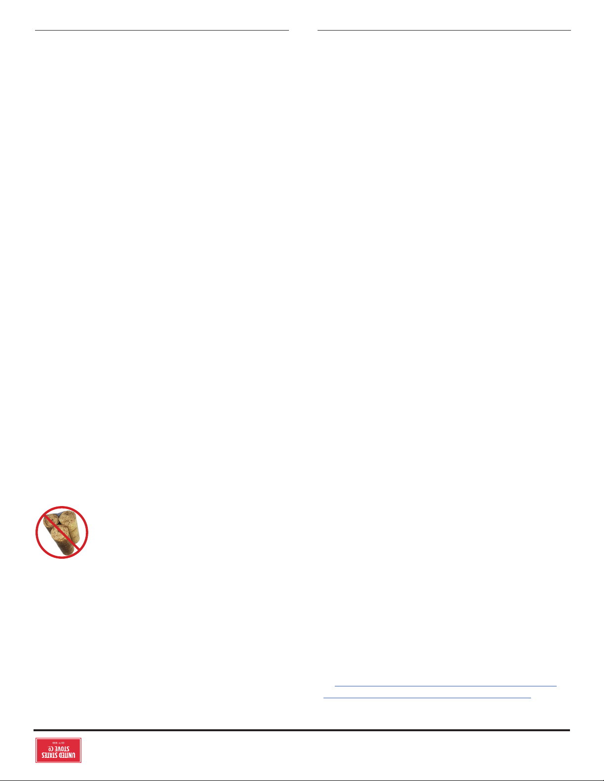
© 2021 United States Stove Company
11
INSTRUCTIONS D’UTILISATION DU BOIS
les caractéristiques de combustion de diverses essences de
bois: http://firewoodresource.com/firewood-btu-ratings/; ou
https://forestry.usu.edu/forest-products/wood-heating. Le
fonctionnement de ce poêle à bois d’une manière non conforme
au manuel du propriétaire annulera votre garantie et est
également contraire à la réglementation fédérale. Les déchets
et autres matériaux inflammables ne doivent pas être brûlés
dans votre poêle. NE BRÛLEZ PAS:
1. Des ordures;
2. Des déchets de tonte ou résidus de jardin;
3. Des matériaux contenant du caoutchouc, incluant les
pneus;
4. Matériaux contenant du plastique;
5. Des déchets de produits du pétrole, des peintures ou
diluants à peinture, ou des produits d’asphalte;
6. Matériaux contenant de l’amiante;
7. Débris de construction ou de démolition;
8. Traverses de voie ferrée ou bois traité sous pression;
9. Fumier ou restes d’animaux;
10. Bois de grève en eau salée ou autres matériaux
précédemment saturés par de l’eau salée;
11. Bois non séché; ou
12. Produits du papier, carton, contreplaqué, ou panneau
de particules. L’interdiction de brûlage de ces matériaux
n’interdit pas l’utilisation d’allume-feu composés de papier,
carton, sciure de bois, cire et substances similaires, aux
fins de démarrer le feu dans un chauage au bois modifié.
La combustion de ces matériaux peut entraîner la libération
de fumées toxiques ou rendre le radiateur inecace et
provoquer de la fumée. Le bois mort posé sur le sol forestier
doit être considéré comme humide et nécessite un temps de
séchage complet. Le bois mort sur pied peut généralement être
considéré comme environ 2/3 assaisonné. Les petits morceaux
de bois sèchent plus rapidement. Toutes les bûches de plus
de 6 po de diamètre doivent être fendues. Le bois ne doit pas
être stocké directement sur le sol. L’air devrait circuler dans les
bûches. Un espace d’air de 24 po à 48 po doit être laissé entre
chaque rangée de bûches, qui doivent être placées à l’endroit le
plus ensoleillé possible. La couche supérieure de bois doit être
protégée de l’élément mais pas des côtés. Un bon indicateur pour
savoir si le bois est prêt à brûler est de vérifier les extrémités
des pièces. Si des fissures rayonnent dans toutes les directions
à partir du centre, le bois doit être susamment sec pour
brûler. Si votre bois grésille dans le feu, même si la surface est
sèche, il se peut qu’il ne soit pas complètement durci et devrait
être séché plus longtemps. Il est EXTRÊMEMENT IMPORTANT
d’utiliser du BOIS SEC uniquement dans votre poêle à bois.
Le bois doit avoir séché pendant 9 à 15 mois, de sorte que la
teneur en humidité (en poids) soit réduite en dessous de 20%
du poids de la bûche. Il est très important de garder à l’esprit
que même si le bois a été coupé pendant un, deux ans ou même
plus, il n’est pas nécessairement sec s’il a été stocké dans de
mauvaises conditions. Dans des conditions extrêmes, il peut
pourrir au lieu de sécher. Ce point ne peut pas être surestimé;
la grande majorité des problèmes liés au fonctionnement d’un
poêle à bois est due au fait que le bois utilisé était trop humide
ou avait séché dans de mauvaises conditions. Ces problèmes
peuvent être:
• problèmes d’allumage
• accumulation de créosote provoquant des feux de cheminée
• faible rendement énergétique
• fenêtres noircies
• combustion de bûches incomplète
Ne brûlez pas de bûches fabriquées à partir
de sciure de bois imprégnée de cire ou de
bûches contenant des additifs chimiques. Les
bûches fabriquées à 100% de sciure compressée
peuvent être brûlées, mais soyez prudent en
brûlant trop de ces bûches en même temps. Commencez avec
une bûche fabriquée et voyez comment le poêle réagit. Vous
pouvez augmenter le nombre de bûches brûlées à la fois, mais
assurez-vous que la température ne dépasse jamais 475 ° F
(246 ° C) sur un thermomètre magnétique pour une installation
sur des tuyaux de poêle à paroi simple ou 900 ° F (482 ° C) sur
un thermomètre à sonde pour installation sur tuyau de poêle
à double paroi. Le thermomètre doit être placé à environ 18 po
(457 mm) au-dessus du poêle. Des températures plus élevées
peuvent entraîner une surchaue et endommager votre poêle.
TESTER VOTRE BOIS
• Lorsque le poêle est bien réchaué, placez un morceau de
bois fendu (environ cinq pouces de diamètre) parallèle à la
porte sur le lit de braises rouges.
• Gardez la commande d’air complètement ouverte et fermez
la porte. Si le bois s’enflamme dans les 90 secondes suivant
le moment où il a été placé dans le poêle, votre bois est
correctement séché. Si l’allumage prend plus de temps, votre
bois est humide.
• Si votre bois siffle et que de l’eau ou de la vapeur s’échappe aux
extrémités de la pièce, votre bois est trempé ou fraîchement
coupé (vert). N’utilisez pas ce bois dans votre poêle. De
grandes quantités de créosote pourraient se déposer dans
votre cheminée, créant des conditions potentielles pour un
feu de cheminée.
ALTÉRER AVERTISSEMENT
Ce chauage au bois a un taux de combustion minimum réglé à
la fabrication, et qui ne peut être modifié. La modification de ce
réglage ou une utilisation autre de ce chauage au bois qui ne
respecterait pas les directives du présent manuel contrevient
aux réglementations fédérales.
EFFICACITÉ
Les rendements peuvent être basés sur la valeur calorifique
inférieure (LHV) ou la valeur calorifique supérieure (HHV)
10
© 2021 United States Stove Company
INSTRUCTIONS D’UTILISATION DU BOIS
NE JAMAIS UTILISER CE PRODUIT SANS SURVEILLANCE
PRÉCAUTIONS DE SÉCURITÉ D'UTILISATION
• NE JAMAIS SURALLUMER CET APPAREIL EN
CONSTRUISANT DES INCENDIES EXCESSIVEMENT
CHAUDS, CE QUI PEUT EN RÉSULTER UN INCENDIE
DE MAISON / IMMEUBLE. VOUS SURCHARGEZ
L'APPAREIL SI IL COMMENCE À LUMINER OU À
DEVIENDRE ROUGE.
• NE PAS MODIFIER LA COMMANDE D'AIR DE
COMBUSTION DE CET APPAREIL AU-DELÀ DE LA
PLAGE DE RÉGLAGE NORMALE.
• NE JAMAIS CONSTRUIRE DES FEUX
EXCESSIVEMENT GRANDS DANS CE TYPE
D'APPAREIL, DES ENDOMMAGER LA BOÎTE À FEU OU
UNE FUITE DE FUMÉE POURRAIENT EN RÉSULTER.
• NE PAS CONSTRUIRE LE FEU TROP PRÈS DE LA
VITRE.
• CHAUD EN FONCTIONNEMENT. TENIR LES ENFANTS,
LES VÊTEMENTS ET LES MEUBLES À L'ÉCART. LE
CONTACT PEUT CAUSER DES BRÛLURES DE LA
PEAU. NE TOUCHEZ PAS L'APPAREIL JUSQU'À CE
QU'IL SOIT REFROIDI.
• FOURNISSEZ DE L'AIR ADÉQUAT POUR LA
COMBUSTION À LA PIÈCE O L'APPAREIL EST
INSTALLÉ.
• INSPECTER LA DOUBLURE DE CHEMINÉE TOUS
LES 60 JOURS. REMPLACER IMMÉDIATEMENT LA
DOUBLURE EN CAS DE ROULEMENT OU DE FUITE DE
FUMÉE DANS LA PIÈCE.
• LES TENTATIVES POUR ATTEINDRE DES TAUX
DE SORTIE DE CHALEUR QUI DÉPASSENT LES
SPÉCIFICATIONS DE CONCEPTION DU CHAUFFAGE
PEUVENT CAUSER DES DOMMAGES PERMANENTS
AU CHAUFFAGE.
• POUR ÉVITER DES BLESSURES, NE PERMETTEZ À
PERSONNE D'UTILISER CET APPAREIL QUI N'EST PAS
FAMILIAL AVEC SON FONCTIONNEMENT CORRECT.
NE PAS FAIRE FONCTIONNER CET APPAREIL SOUS
L'INFLUENCE D'ALCOOL OU DE DROGUES.
• SI UN COMPOSANT DE L'APPAREIL EST MANQUANT
OU ENDOMMAGÉ, CONTACTEZ IMMÉDIATEMENT
VOTRE CONCESSIONNAIRE. NE PAS FAIRE
FONCTIONNER CET APPAREIL AVEC DES PIÈCES
MANQUANTES OU ENDOMMAGÉES.
MISES EN GARDE: RISQUES D'INCENDIE MAISON
• NE CONSERVEZ PAS LE BOIS SUR UN PROTECTEUR
DE PLANCHER, SOUS LES TUYAUX DE POÊLE OU
N'IMPORTE O DANS LES DÉGAGEMENTS DES
SURFACES COMBUSTIBLES SPÉCIFIÉES POUR CET
APPAREIL.
• NE JAMAIS FAIRE FONCTIONNER AVEC DES TUBES
SECONDAIRES, DU CARTON DE FIBRE OU DE
L'ISOLANT ENLEVÉ.
ATTENTION:
LES ENFANTS DOIVENT ÊTRE ALERTÉS AUX DANGERS
LIÉS À DES TEMPÉRATURES DE SURFACE ÉLEVÉES.
NE LAISSEZ JAMAIS DE PETITS ENFANTS SANS
SUPERVISION LORSQU'ILS SE TROUVENT DANS
LA MÊME PIÈCE QUE L'APPAREIL PENDANT LE
FONCTIONNEMENT. POUR ÉVITER LES BRÛLURES,
PORTER TOUJOURS DES VÊTEMENTS DE PROTECTION,
DES GANTS DE PROTECTION EN CUIR ET UNE
PROTECTION DES YEUX LORS DU RAVITAILLEMENT
OU DE L'ENTRETIEN AU FEU. SOYEZ TOUJOURS
CONSCIENT DES SURFACES CHAUFFÉES. LA CHALEUR
RADIANT DE L'APPAREIL PEUT POTENTIELLEMENT
DÉCOLORER, FONDRE OU MÊME ALLUMER LES
MATÉRIAUX COMBUSTIBLES. GARDEZ TOUS LES
MATÉRIAUX COMBUSTIBLES BIEN ÉLOIGNÉS DU
CHAUFFAGE!
AVERTISSEMENT: RISQUE D'EXPLOSION
• N'UTILISEZ JAMAIS DE PRODUITS CHIMIQUES,
D'ESSENCE, DE CARBURANT DE LANTERNE DE TYPE
ESSENCE, DE KÉROSÈNE, DE LIQUIDE À BRIQUET
AU CHARBON OU DE LIQUIDES INFLAMMABLES
SIMILAIRES POUR ALLUMER OU «RAFRAÎCHIR» UN
INCENDIE DANS L'APPAREIL.
• GARDER TOUS LES LIQUIDES INFLAMMABLES, EN
PARTICULIER L'ESSENCE, HORS DE LA PROXIMITÉ
DE L'APPAREIL - QUE CE SOIT EN UTILISATION OU
EN STOCKAGE.
UTILISATION DU POÊLE À BOIS
Votre appareil de chauage a été conçu pour brûler uniquement
du bois naturel bien séché; aucun autre matériau ne doit être
brûlé. N’importe quel type de bois naturel bien séché peut
être utilisé dans votre poêle, mais certaines variétés ont
de meilleurs rendements énergétiques que d’autres. Des
rendements plus élevés et des émissions plus faibles résultent
généralement de la combustion de bois durs séchés à l’air, par
rapport aux résineux ou aux feuillus trop verts ou fraîchement
coupés. Les ressources suivantes peuvent aider à apprendre
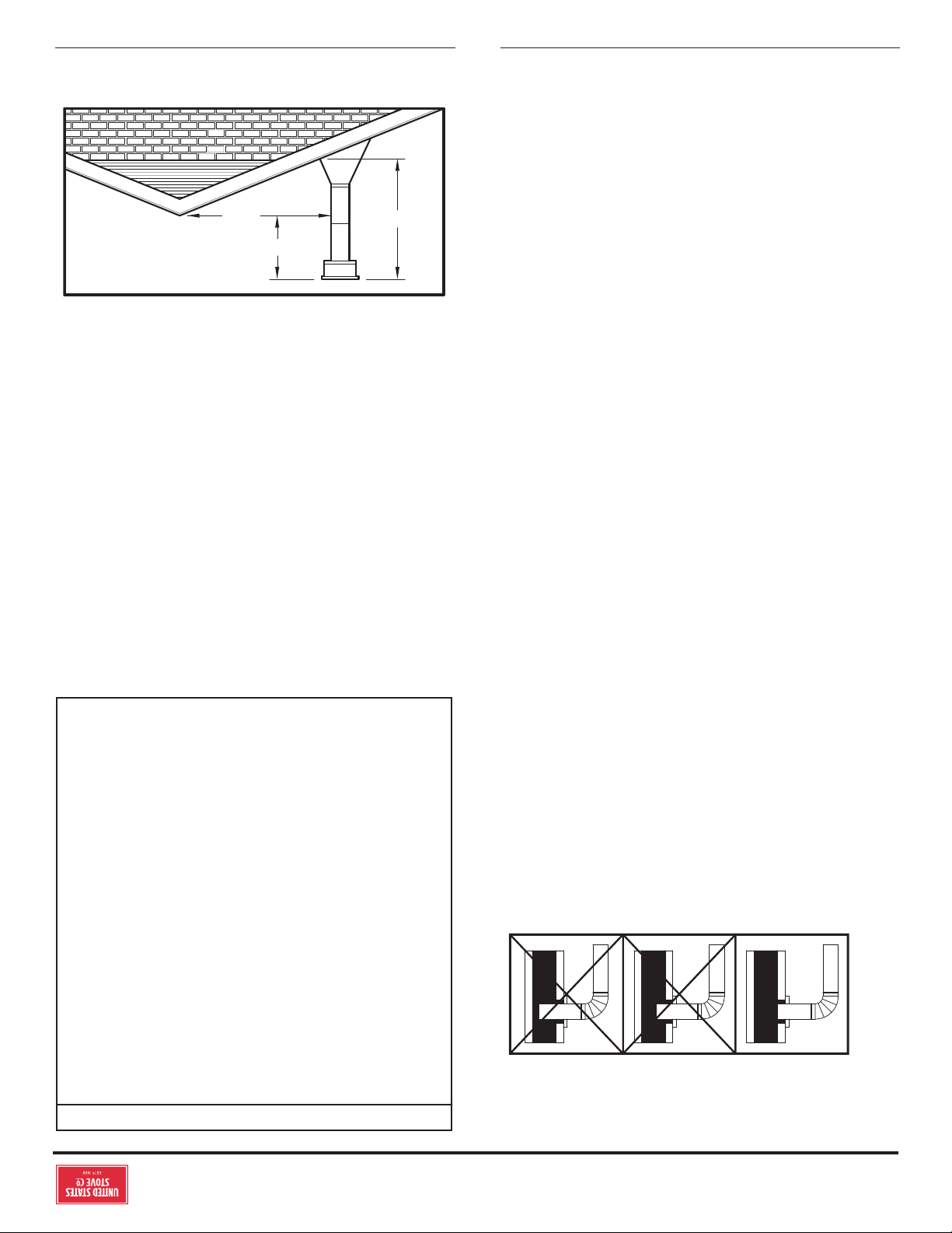
© 2021 United States Stove Company
9
dessus du toit et au moins 0,6 m au-dessus du point le plus
haut situé dans un rayon de 1,5 m autours du sommet de la
cheminée.
BON MAUVAIS MAUVAIS
IMPORTANCE D’UN TIRAGE ADÉQUAT
Le tirage est une force déplaçant l’air de l’appareil vers la
cheminée. La quantité de tirage dans votre cheminée dépend
de la longueur de la cheminée, son emplacement géographique
local, les obstructions à proximité et d’autres facteurs. Trop de
tirage peut causer des températures excessives dans l’appareil
et pourrait l’endommager. Un tirage inadéquat peut causer
des retours de fumée dans la pièce et causer l’obturation de la
cheminée. Un tirage inadéquat causera des fuites de fumée par
l’appareil dans la pièce, s’infiltrant par l’appareil, et les joints
du conduit de raccordement. Un brûlage incontrôlable ou une
température excessive indique un tirage excessif.
Les cheminées remplissent deux fonctions:
1. Comme un moyen d’épuiser la fumée et les gaz de
combustion qui sont le résultat de la combustion du
carburant.
2. La cheminée fournit un «tirage» qui permet à l’oxygène
d’être introduit en continu dans l’appareil, de sorte qu’une
combustion correcte est possible. Ce poêle repose sur un
tirage naturel pour fonctionner.
AVIS: Toujours fournir une source d’air frais dans la pièce où se
trouve le poêle. Si vous ne le faites pas, vous risquez de manquer
d’air dans d’autres appareils à combustion et de développer des
conditions dangereuses, un incendie ou la mort.
POINTS IMPORTANTS DE L’INSTALLATION
1. Choisissez le conduit/gaine de cheminée en fonction de la
taille de la buse de l’appareil. Cet insert exige un conduit de
0,125 m minimum de diamètre.
2. Ne jamais connectez cet appareil à un conduit de cheminée
déjà utilisé par un autre appareil.
3. Le conduit de cheminée doit respecter toutes les conditions
de hauteur minimale.
4. N’utilisez jamais un conduit de cheminée pour ventiler une
cave ou un sous-sol.
Contactez les autorités locales pour définir les méthodes
approuvées d’installation et déterminer la nécessité d’obtenir
un permis et/ou de réaliser une inspection.
ATTENTION:
• ASSUREZ-VOUS QUE VOTRE CHEMINÉE EST
CONSTRUITE EN TOUTE SÉCURITÉ ET EN BONNE
RÉPARATION. FAITES INSPECTER LA CHEMINÉE PAR
LE SERVICE DES INCENDIES OU UN INSPECTEUR
QUALIFIÉ. VOTRE COMPAGNIE D’ASSURANCE
DOIT ÊTRE EN MESURE DE RECOMMANDER UN
INSPECTEUR QUALIFIÉ.
• CANADA INSTALLATIONS EXIGE QUE CE FOYER DOIT
ÊTRE INSTALLÉ AVEC UN CHEMINÉE CONTINU DE 6
POUCES DE DIAMÈTRE S’ÉTENDANT DE L’INSERT DU
FOYER AU HAUT DE LA CHEMINÉE. LA DOUBLURE DE
CHEMINÉE DOIT ÊTRE CONFORME AUX EXIGENCES
DE CLASSE 3 DE CAN / ULC-S635, NORME POUR
LES SYSTÈMES DE DOUBLURE POUR CHEMINÉES
ET ÉVENTS DE MAÇONNERIE EXISTANTS OU
CONSTRUITS EN USINE, OU CAN / ULC-S640, NORME
POUR LES SYSTÈMES DE DOUBLURE POUR LES
NOUVELLES CHEMINÉES DE MAÇONNERIE.
• SCELLER EN PERMANENCE TOUTE OUVERTURE
ENTRE LA MAÇONNERIE DU CHEMINÉE ET LA
MAÇONNERIE DE FAÇADE.
CHEMINÉE DE MAÇONNERIE
Avant d’utiliser une cheminée de maçonnerie existante,
nettoyez la cheminée, inspectez le conduit/gaine et réalisez
toute réparation nécessaire afin de garantir une utilisation sans
danger. Cet appareil exige un conduit/gaine continu en acier
inoxydable installé entre la buse et le chapeau de la cheminée.
Réalisez les réparations avant la fixation de l’insert. Le tuyau
de connexion de l’insert et les accessoires nécessaires pour
raccorder directement à la cheminée de maçonnerie sont
détaillés dans les instructions d’installation. Si la cheminée doit
traverser un mur inflammable avant d’entrer dans le conduit
de cheminée principal, consultez un maçon qualifié ou un
négociant de cheminée pour déterminer le choix de matériaux
appropriés conformément aux normes en vigueur. L’installation
doit être conforme aux normes incendie et de construction et
à la dernière édition de NFPA 211. S’il y a une ouverture située
à la base du foyer prévue pour le nettoyage, il faut la fermer
complètement.
Règle 2-10-3
Faîtage
3 pi min.
2 pi min.
10 pi
INSTALLATION
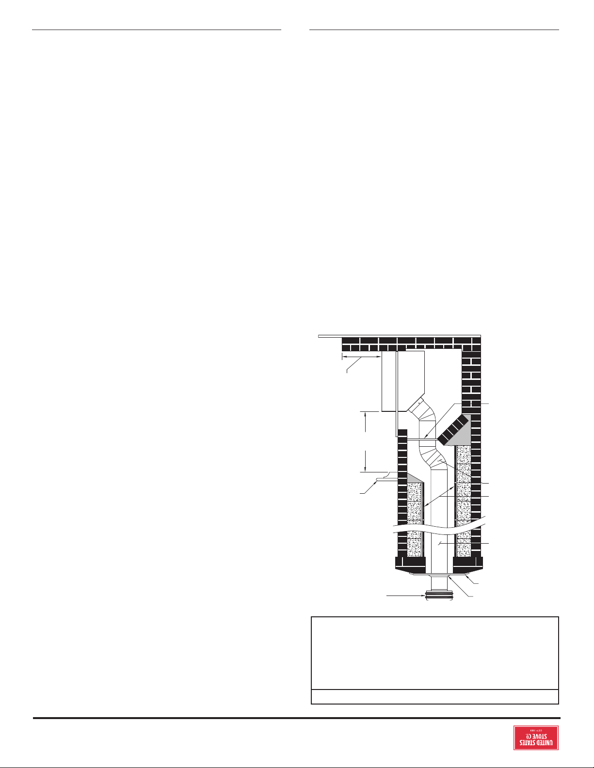
8
© 2021 United States Stove Company
AVERTISSEMENT:
RISQUE D’INCENDIE - NE LAISSEZ PAS DE MATÉRIAUX
INFLAMMABLES (TAPIS, MEUBLES, CARBURANTS)
SUR LA PLAQUE DE PROTECTION DU SOL. TOUS
LES MATÉRIAUX INFLAMMABLES DOIVENT ÊTRE
POSITIONNÉS EN DEHORS DU PÉRIMÈTRE DE
DÉGAGEMENT MINIMAL.
CHEMINÉE DE MAÇONNERIE
CHAMBRE SCELLÉE: CET ESPACE
DOIT ÊTRE SCELLÉ AVEC UN
MATÉRIAU NON COMBUSTIBLE
POUR EMPÊCHER L’ENTRÉE DE
FUMÉE DANS LES PIÈCES À VIVRE. IL
FAUT CEPENDANT PRÉVOIR DES
ACCOMMODATIONS POUR
L’INSPECTION ET LE NETTOYAGE
GAINE/DEVOIEMENT FLEXIBLE
DE 15 CM DE DIAMÉTRE
CONDUIT DE CHEMINÉE DE
MAÇONNERIE
COLLET DE SOLIN CHAPEAU DE PLUIE
LINTEAU
(INFLAMMABLE)
PLAQUE DE PROTECTION
DU SOL (RESPECTEZ LE
DÉGAGEMENT MINIMAL)
RESPECTEZ LE
DÉGAGEMENT
MINIMAL
SOLIN (NON COMBUSTIBLE)
AVEC JOINT DE SILICONE
GAINE EN ACIER INOXYDABLE
UL 1777: INSTALLÉE JUSQU’AU
CHAPEAU DE LA CHEMINÉE.
SUIVEZ LES INSTRUCTIONS
D’INSTALLATION DU
FABRICANT
1. Nettoyez l’ouverture du foyer et enfermez les cendres dans
un récipient métallique fermé..
2. Installez un conduit/gaine de cheminée continu en acier
inoxydable de diamètre minimal de 152 mm. La gaine
doit s’étendre jusqu’au sommet de la cheminée. Utilisez
uniquement des conduits/gaines qui répondent aux
normes de sécurité. Suivez les instructions d’installation
du conduit/gaine fournies par le fabricant.
3. Enlevez ou verrouillez le registre de foyer dans la position
ouverte. Observation: La plaque de maçonnerie pourrait
être enlevée pour accommoder le conduit/gaine de
cheminée si ceci n’aaiblit pas tout élément structurel du
foyer ou du conduit de cheminée, ni réduit la protection
des matériaux inflammables conformément aux normes
de construction. Consultez les autorités locales ou les
services incendie avant de faire ceci.
4. Enlevez l’appareil de sa palette, enlevez tous les emballages
et tout article stocké dans l’insert.
5. AVERTISSEMENT: Tout foyer dont les pièces ont été
retirées ou modifiées pour permettre l’installation de cet
appareil DOIT avoir une plaque d’avertissement installée
de façon permanente dans un endroit visible indiquant que
le foyer est impropre à l’utilisation avec du combustible
solide. Cette unité était livrée avec une étiquette
d’avertissement en métal. Fixez de façon permanente la
plaque d’avertissement à un endroit visible dans le foyer.
Après avoir choisi un emplacement visible dans le foyer,
fixez définitivement la plaque d’avertissement en la vissant
ou en la clouant. Remarque: Utilisez les trous de l’étiquette
pour marquer et pré-percer les trous nécessaires pour fixer
l’étiquette..
6. Positionnez l’appareil dans l’ouverture du foyer jusqu’à ce
que la lèvre supérieure de la chemise d’air soit alignée avec
la façade du foyer.
7. Nivelez l’appareil en ajustant les vis à l’arrière de l’appareil.
8. Connectez le conduit/gaine de cheminée à l’appareil en
utilisant un adaptateur en acier inoxydable installé à l’aide
d’un minimum de 3 vis autotaraudeuses. Le conduit/gaine
DOIT être attaché avec l’extrémité mâle (ou ondulée)
de l’adaptateur à l’intérieur de la buse de l’appareil pour
permettre la condensation et/ou le ruissellement de
créosote dans l’insert.
9. Cet appareil doit être connecté à un conduit/gaine en acier
inoxydable, conforme à la norme UL1777, et installé entre
la buse et le chapeau conformément aux spécifications
énumérées dans les pages précédentes.
TIRAGE DE CHEMINÉE
OBSERVATION: POUR CET APPAREIL, UNE MESURE DE
TIRAGE DE 0,126 [12,45] à 0,151 [14,94] (colonne d’eau en
cm, [Pa]) EST EXIGÉE AFIN D’OBTENIR UNE COMBUSTION
CORRECTE.
Le tirage est créé par la cheminée, et non PAS PAR
L’INSERT. L’échappement de fumée dans la maison ou
l’excès d’accumulation de condensation ou de créosote dans
la cheminée sont des avertissements que la cheminée ne
fonctionne pas convenablement. Corrigez ce problème avant
d’utiliser l’appareil. Les possibles causes de mauvais tirage sont
énumérées ci-dessous:
1. Le tuyau de connexion est peut être poussé trop
profondément à l’intérieur du conduit de cheminée arrêtant
ainsi le tirage ;
2. Si l’insert atteint des températures pas assez chaudes
durant son fonctionnement, de l’eau se condensera dans
le conduit de cheminée et retournera ainsi dans l’insert.
La formation de créosote sera rapide et pourrait bloquer le
conduit de cheminée. Utilisez cet appareil à un niveau de
feu assez haut pour garder le conduit de cheminée chaud
et empêcher ainsi cette condensation ;
3. Si le feu brûle bien mais crée quelquefois de la fumée
excessive ou des feux à combustion lente, cela pourrait
être causé par la position trop basse du sommet de la
cheminée comparéeà une autre partie de la maison ou un
arbre proche. Le vent qui passe au dessus d’une maison ou
un arbre retombe sur la cheminée rabattant ainsi la fumée.
Le sommet de la cheminée devrait être au moins 0,9 m au-
INSTALLATION
© 2021 United States Stove Company
7
m au-dessus du point le plus haut situé dans un rayon de
1,5 m autours du sommet de la cheminée. Voir section des
Connexions du conduit de cheminée de ce manuel.
3. Insert à dégagement nul. Ces cheminées et les conduits de
cheminée doivent respecter les minima de spécifications
et directives. Les inserts à dégagement zéro doivent être
répertoriés et appropriés pour l’utilisation de combustibles
solides. Le diamètre du conduit de cheminée doit mesurer
au minimum 17 cm pour accommoder une gaine de
cheminée continue en acier inoxydable installée entre la
buse de l’appareil et le sommet de la cheminée. Seules
les pièces détachables, qui sont facilement replacées
(c.-à-d. les pièces de protection, les panneaux, les portes
et les briques réfractaires latérales et celles situées à
l’arrière), peuvent être enlevées. Ces pièces doivent être
stockées précautionneusement si l’appareil est déplacé. Le
démontage de n’importe quelle pièce, qui rend la cheminée
inutilisable pour brûler des combustibles solides, implique
qu’une étiquette permanente soit apposée par l’installateur
afin d’indiquer que l’insert n’est plus approprié pour
brûler des combustibles solides à moins que les pièces
manquantes soient replacées et la cheminée restaurée à
son état original et certifié.
4. Les chapeaux de cheminée. Les chapeaux de conduit avec
grillage et pare-étincelles doivent pouvoir être déplacés
pour permettre l’inspection fréquente et le nettoyage
régulier. Sinon ils devraient être enlevés pour éviter le
bouchage. Consultez les autorités locales et les normes de
construction.
5. Le gaine de cheminée. La cheminée doit être appropriée
pour la combustion solide. Installez une gaine continue en
acier inoxydable entre la buse de l’appareil et le sommet de
la cheminée. La gaine doit être conforme à la norme UL1777.
6. Dégagements des matériaux inflammables. Le foyer et le
conduit de cheminée doivent être inspectés pour garantir
un dégagement susant avec des matériaux inflammables.
Ceci inclut le dessus, les côtés, la façade et l’arrière de
même que tout matériau inflammable situé aux alentours
du conduit de cheminée et du linteau. Votre inspecteur
local ou les services incendie devraient pouvoir indiquer si
une vieille cheminée respecte les normes actuelles et est
ainsi appropriée pour cette utilisation. Voir aussi schéma
1 et 2.
7. Conditions d’air. Cet appareil exige un approvisionnement
susant d’air pour fonctionner ecacement et de
façon sûre. Ce paramètre peut constituer une norme de
construction. Un approvisionnement insusant d’air
causera une mauvaise combustion, un fonctionnement
inecace, l’accumulation de créosote, un refoulement d’air
et de fumée dans les pièces à vivre. Si n’importe laquelle
des conditions suivantes est incontestablement présente,
une alimentation d’air doit être installée:
a. L’appareil actuel de chauage créé un refoulement de fumée,
des odeurs excessives dans les pièces à vivre ou fonctionne
inecacement ;
b. Ouvrir une fenêtre ou une porte réduit les problèmes ou
symptômes décrits ci-dessus ;
c. Le bâtiment est construit avec une barrière de vapeur
étanche, une installation hermétique des fenêtres ou est
équipé d’un extracteur motorisé ;
d. Condensation excessive sur les fenêtres durant l’hiver
e. Le bâtiment est installé avec un système de ventilation ;
f. Si, une fois installé, l’appareil de combustion solide ne
tire pas de façon constante, présente une combustion faible
ou inecace, un refoulement d’air ou des fumées de retour
lors de la recharge en combustible.
LES CONDITIONS DE TIRAGE
AVERTISSEMENT:
RISQUE D’INCENDIE - UN TIRAGE EXCESSIF PEUT
CAUSER LA SURCHAUFFE ET UN INCENDIE. N’UTILISEZ
PAS CET APPAREIL AVEC UN TIRAGE DE CONDUIT DE
CHEMINÉE DÉPASSANT 0,15 CM DE COLONNE D’EAU.
(0,1 PA).
Le conduit de cheminée est un élément critique pour un
fonctionnement correct et ecace de n’importe quel appareil
de chauage. Les appareils de chauage ne créent pas le tirage,
il est fourni par le conduit de cheminée. Cet appareil exige un
tirage de 0,125 cm de colonne d’eau (0,1 Pa) au niveau de la
buse.
Pour obtenir un bon tirage, votre conduit de cheminée doit
respecter trois conditions ; une hauteur minimale de 4,5
m.,mesurée entre le dessus du foyer et le sommet de la
cheminée, une hauteur minimale de 0,9 m au-dessus du point
de pénétration du conduit dans le toit, et une hauteur minimale
de 0,6 m au-dessus du point le plus haut situé dans un rayon de
1,5 m autours du sommet de la cheminée.
La cheminée doit également présenter un profil transversal
minimum et maximum. Pour cette raison, un conduit/gaine de
cheminée continu en acier inoxydable, installé entre la buse de
l’appareil et le sommet de la cheminée, est exigé. Un adaptateur
en acier inoxydable est recommandé pour attacher la gaine/
conduit d’acier inoxydable à la buse. La partie mâle (ou ondulée)
de l’adaptateur doit être installée à l’intérieur de la buse pour
permettre à la condensation ou la créosote présente dans la
gaine/conduit de retourner dans l’insert. La gaine/conduit de
cheminée et/ou les adaptateurs doivent être attachés de façon
permanente en utilisant au moins trois vis à chaque connexion.
Il est plus dicile d’atteindre et conserver les températures
de fonctionnement optimal pour les conduits de cheminée
installés à l’extérieur de la maison ou sur un mur extérieur. Cela
pourrait causer l’accumulation de créosote, moins de tirage, le
refoulement d’air et des problèmes de performance de l’appareil.
Ce type d’installation devrait donc être évité.
INSTALLATION
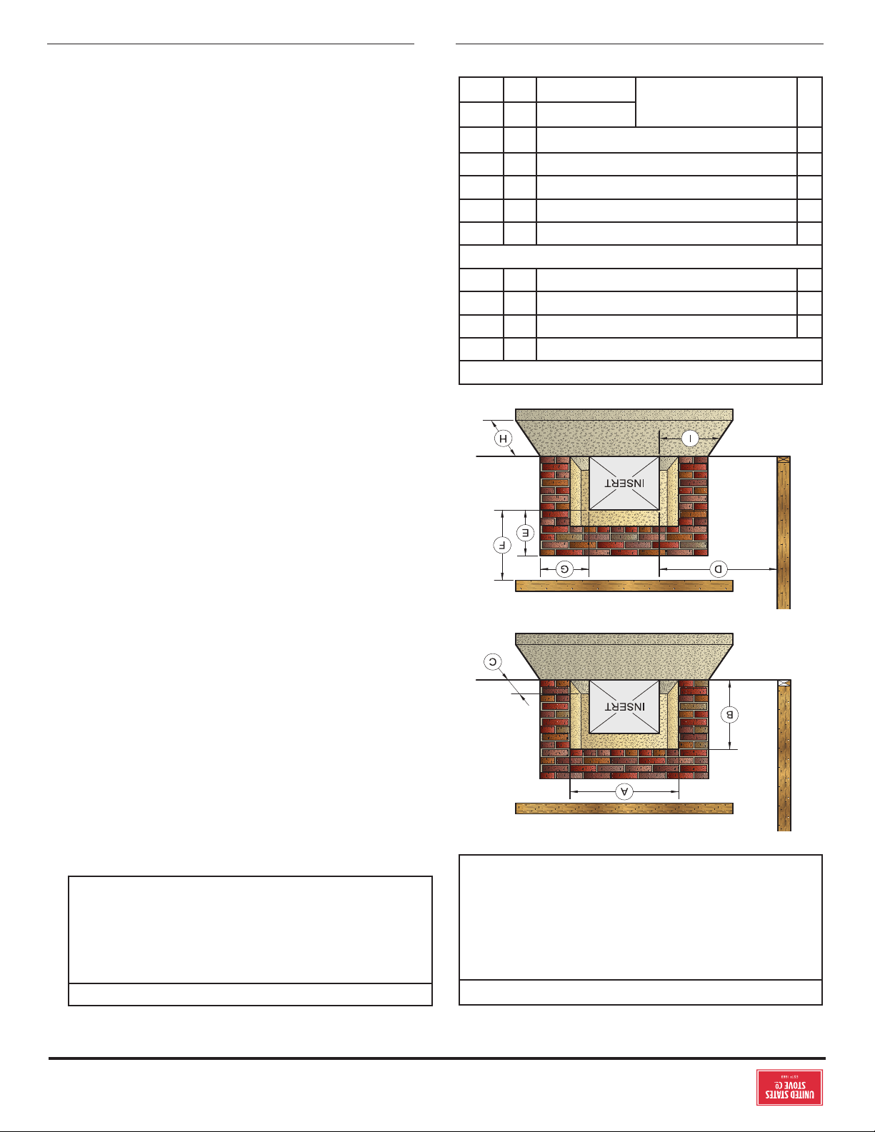
6
© 2021 United States Stove Company
DÉGAGEMENTS AUX COMBUSTIBLES
AVERTISSEMENT: RISQUE D'INCENDIE
RESPECTEZ LES DÉGAGEMENTS MINIMAUX AUX
COMBUSTIBLES INDIQUÉS DANS CE MANUEL ET
SUR LES ÉTIQUETTES FIXÉES À L'APPAREIL. NE
PAS STOCKER DE BOIS, TOUT TYPE DE VAPEURS OU
DE LIQUIDES INFLAMMABLES, PLACER MEUBLES,
TAPIS, TAPIS, VÊTEMENTS OU AUTRES OBJETS
COMBUSTIBLES DANS LA ZONE DE DÉGAGEMENT.
LINTEAU
MUR LATERAL
LINTEAU
MUR LATERAL
Dimensions d’ouverture du foyer
po mm
A Hauteur Minimum 29 737
B Largeur Minimum 23 585
C Profondeur Minimum 14 356
Dégagements des matériaux inflammables
D Min. Distance à la paroi latérale 9 229
E Min. Distance à la partie supérieure 14 356
F Min. Distance jusqu’au manteau 19 483
G Min. Distance à la garniture latérale 9 229
H Min. Protecteur de plancher avant 17 432
I
Min. Côté protecteur de
plancher
USA 6 153
CAN 8 204
AIR DE COMBUSTION EXTÉRIEUR
ATTENTION:
BRANCHEZ TOUJOURS CET APPAREIL À UNE CHEMINÉE
ÉVENTÉE À L'EXTÉRIEUR. NE JAMAIS VENTILER DANS
UNE AUTRE PIÈCE, UN ESPACE DE CHENILLES, UN
GRENIER OU À L'INTÉRIEUR D'UN BÂTIMENT. NE PAS
RACCORDER CET APPAREIL À UN FUMÉ DE CHEMINÉE
SERVANT UN AUTRE APPAREIL
Votre appareil lui-même ne crée pas de courant d’air. Le tirage
est assuré par la cheminée. Pour aider à fournir le tirage requis,
un kit d’air frais (4FAK) est disponible à l’achat auprès de votre
revendeur de poêles local. Lorsqu’il est installé correctement,
le kit 4FAK est conçu pour fournir le tirage nécessaire au bon
fonctionnement. Pour obtenir un tirage adéquat, votre cheminée
doit répondre aux trois exigences de hauteur minimale détaillées
dans la figure 8. Un tirage minimum de 0,05 w.c. (mesuré dans
la colonne d’eau) est nécessaire pour un tirage correct afin
d’éviter les soufflages de dos, les déversements de fumée et
pour maximiser les performances. Des jauges pour mesurer le
tirage sont facilement disponibles dans les magasins de poêles
et sont économiques à louer ou à acheter. Des facteurs tels
que le vent, la pression barométrique, les arbres, le terrain et la
température de la cheminée peuvent avoir un eet négatif sur le
tirage. Le fabricant ne peut être tenu responsable des facteurs
externes conduisant à une rédaction moins qu’optimale. Si
vous avez un problème avec un tirage insusant, vous devez
contacter un entrepreneur en chauage et en refroidissement
agréé pour obtenir de l’aide pour résoudre le problème.
LA CONDITION DE LA CHEMINÉE ET LES
CONDITIONS DE DÉGAGEMENT NUL
Une cheminée de maçonnerie doit respecter des normes
minimales, la norme NFPA 211, ou l’équivalent pour une
installation sûre. Contactez un professionnel, un installateur
accrédité, l’inspecteur des autorités locales ou les pompiers
pour plus d’informations sur les conditions d’installation.
Votre compagnie d’assurances devrait pouvoir recommander
un inspecteur qualifié. Les inspections doivent couvrir les
vérifications suivantes:
1. La condition de la cheminée et du conduit de cheminée. La
cheminée de maçonnerie et le conduit de cheminée doivent
être inspectés avant l’installation de cet appareil. Ils ne
doivent pas présenter de fissures, de mortier de mauvaise
qualité, de dépôts de créosote, d’obstruction ou tout autre
preuve de détérioration. N’importe lequel de ces problèmes
devra être réparé avant l’installation. N’ENLEVEZ PAS LES
BRIQUES ou LE MORTIER de la cheminée existante lors de
l’installation de cet appareil.
2. Taille du conduit de cheminée. Le diamètre minimum du
conduit de cheminée est 152 mm. Maintenez une hauteur
minimum de conduit de cheminée (mesurée du dessus de
l’appareil au sommet de la cheminée) de 4,5 m. Les conduits
doivent dépasser le toit par au moins 0,9 m et au moins 0,6
INSTALLATION
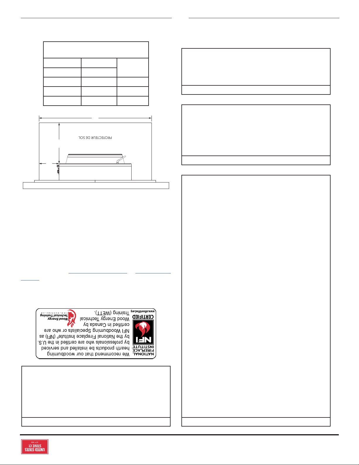
© 2021 United States Stove Company
5
INSTALLATION
AVIS DE SÉCURITÉ:
• SI CE POÊLE N'EST PAS INSTALLÉ CORRECTEMENT,
UN INCENDIE PEUT EN RÉSULTER. POUR
RÉDUIRE LES RISQUES D'INCENDIE, SUIVEZ LES
INSTRUCTIONS D'INSTALLATION.
• CONSULTEZ VOTRE DÉPARTEMENT MUNICIPAL
DU BÂTIMENT OU LES AGENTS DES INCENDIES AU
SUJET DES PERMIS, RESTRICTIONS ET EXIGENCES
D'INSTALLATION DANS VOTRE RÉGION.
• UTILISEZ DES DÉTECTEURS DE FUMÉE DANS LA
PIÈCE O VOTRE POÊLE EST INSTALLÉ.
• GARDEZ LES MEUBLES ET LES DRAPS BIEN
ÉLOIGNÉS DU POÊLE.
• NE JAMAIS UTILISER D'ESSENCE, DE CARBURANT
DE LANTERNE DE TYPE ESSENCE, DE KÉROSÈNE,
DE LIQUIDE POUR BRIQUET AU CHARBON OU
DE LIQUIDES SIMILAIRES POUR ALLUMER OU
«RAFRAÎCHIR» UN FEU DANS CE CHAUFFAGE.
GARDER TOUS CES LIQUIDES BIEN ÉLOIGNÉ DU
CHAUFFAGE PENDANT SON UTILISATION.
• EN CAS D'INCENDIE DE CHEMINÉE, METTEZ LES
CONTRÔLES D'AIR EN POSITION FERMÉE, QUITTEZ
LE BÂTIMENT ET APPELEZ IMMÉDIATEMENT LE
SERVICE DES INCENDIES!
• NE BRANCHEZ AUCUN CONDUIT OU SYSTÈME DE
DISTRIBUTION D'AIR.
• UNE SOURCE D'AIR FRAIS DANS LA PIÈCE OU
L'ESPACE CHAUFFÉ SERA FOURNIE EN CAS DE
BESOIN.
• N'INSTALLEZ PAS CET APPAREIL DANS UNE MAISON
MOBILE, UNE MAISON MANUFACTURÉE, UNE
REMORQUE OU UNE TENTE (AUCUNE EXCEPTION
PAR HUD NORME FÉDÉRALE: 24 CFR CH.XX).
ATTENTION:
NE PAS RACCORDER UN APPAREIL DE BRÛLAGE AU BOIS
À UN ÉVENT À GAZ EN ALUMINIUM DE TYPE B. CE N'EST
PAS SÛR. UTILISER DE LA MAÇONNERIE APPROUVÉE
OU UNE CHEMINÉE D'APPAREIL DE CHAUFFAGE DE
BÂTIMENT HOMOLOGUÉE UL 103 HT (É.-U.). UTILISEZ
UNE CHEMINÉE DE 6 ”DE DIAMÈTRE, ASSEZ ÉLEVÉE
POUR CRÉER UN TIRAGE SUFFISANT.
ATTENTION:
FOURNISSEZ DE L'AIR DE COMBUSTION ADÉQUAT À LA
PIÈCE O L'APPAREIL EST INSTALLÉ. LA RESTRICTION
DE L'AIR DE COMBUSTION ENTRAÎNERA UN FEU
PARAÎTRE QUI CAUSE UNE ACCUMULATION DE SUIE OU
DE CRÉOSOTE ET RÉDUIT GRANDEMENT L'EFFICACITÉ.
ATTENTION:
VÉRIFIEZ QUE L'APPAREIL EST CORRECTEMENT
INSTALLÉ AVANT DE TIRER POUR LA PREMIÈRE
FOIS. CET APPAREIL DOIT ÊTRE INSTALLÉ PAR UN
INSTALLATEUR QUALIFIÉ POUR ASSURER UNE
INSTALLATION CORRECTE ET SÛRE. N'UTILISEZ
JAMAIS DE COMPROMIS TEMPORAIRES OU DE
CHANGEMENT PENDANT L'INSTALLATION.
US Stove recommande fortement que votre poêle soit installé
par un technicien qualifié NFI (US) ou WETT (Canada). Pour
trouver l’installateur qualifié le plus proche, accédez à: https://
nficertified.org; or https://www.wettinc.ca/
PLAQUE DE PROTECTION DU SOL
Un plancher solide incombustible, en béton ou en maçonnerie
pleine, doit s’étendre de 6 ”(153 mm) de chaque côté du corps
de l’appareil et de 17” (432 mm) devant la face de l’appareil.
Lorsque le revêtement de sol combustible se situe dans ces
dimensions minimales, il doit être recouvert d’un protecteur
de sol homologué, avec une valeur R d’au moins 1,4. Vérifiez les
codes du bâtiment locaux si vous souhaitez finir le revêtement
de sol avec des carreaux de sol en céramique coulés.
C
B
Spécifications minimales de protection de plancher
A
PROTECTEUR DE SOL
Clé po mm
A 17 432
B *6 *153
C
38 USA 966
42 CAN 1067
* = Les installations canadiennes
nécessitent 8 po (204 mm)
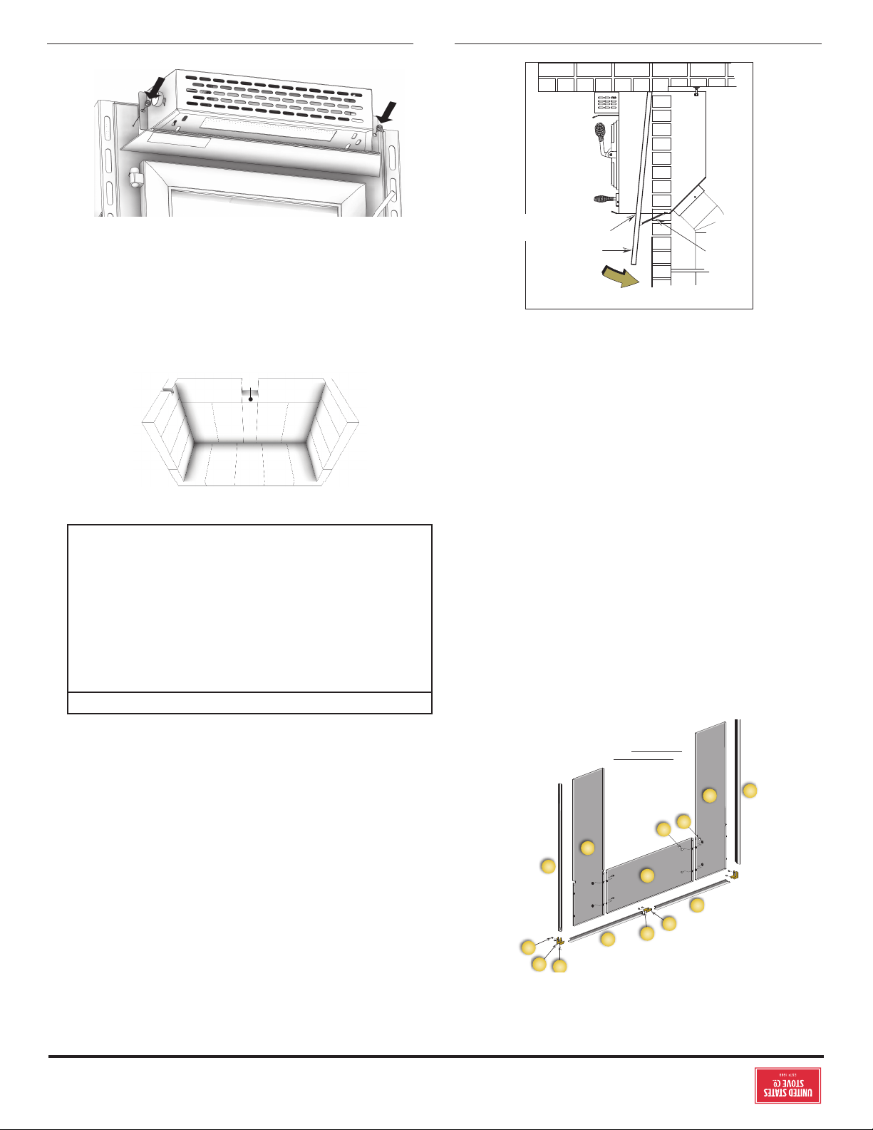
4
© 2021 United States Stove Company
INSTRUCTIONS DE MONTAGE
POUR L’ASSISTANCE TECHNIQUE, APPELEZ: 8007502723 EXT 5050
ASSEMBLEZ L’HABILLAGE
a
q
b
f
e
g
h
c
d
j
k
m
n
p
SURROUND ASSEMBLY
VIEW FROM BACK
ASSEMBLAGE DE
L’HABILLAGE - VUE DE
DERRIÈRE
1. Posez les panneaux avec le côté face vers le bas sur un tapis
ou toute autre surface douce afin de protéger la finition des
pièces lors de leur assemblage. L’habillage consiste de deux
panneaux latéraux, un panneau supérieur et de bandes
décoratives.
2. Boulonnez le panneau supérieur (a) aux panneaux latéraux
(b et q) de sorte que les surfaces supérieures affleurent
l’une à l’autre à l’aide des éléments c et d.
3. Assemblez le cadre de garniture. La garniture se compose
d’une pièce latérale gauche (f) et droite (e) et d’une pièce
supérieure fendue (gauche h, droite g). Ceux-ci sont reliés
par des connecteurs d’angle (m, n, & p) et deux connecteurs
centraux droits (j & k). Ceux-ci glissent dans le canal à
l’arrière du cadre et sont fixés avec deux vis de réglage (p)
dans chaque pièce.
4. Les bandes décoratives glissent sur l’habillage et sont
fixées à la base de chaque côté avec une vis à métal.
5. L’habillage, une fois assemblé, est alors glissé par dessus
l’appareil. Des entailles dans les deux panneaux latéraux
accommodent des encoches situées en haut de l’appareil.
SPRING
SURROUND
Slots in surround
slide of rebox top
Figure 6. Surround Installation
Installation de l’habillage
RESSORT
HABILLAGE
Entailles dans
l’habillage glissent sur
le dessus de l’insert
6. L’habillage est tenu en place grâce à deux ressorts situés en
haut à chaque coin de l’appareil (figure 6).
7. Connectez le cordon d’alimentation de la soufflerie à la
prise.
8. Les briques réfractaires rallongent la vie de votre insert
et rayonne la chaleur de façon plus égale. Si des briques
réfractaires ont été enlevées pour positionner l’appareil, il
faut les replacer avant d’allumer l’appareil. Voir figure 7 pour
la bonne orientation et le positionnement correct. Installez
en premier la rangée de briques située à l’arrière suivie
par celle de chaque côté et enfin les briques réfractaires
situées entre chaque côté.
INSTALLATION DE BRIQUES
RÉFRACTAIRES
ATTENTION: RISQUE D’INCENDIE !
• REMPLACER LES BRIQUES À FEU AVANT DE TIRER
LE POÊLE À BOIS. POSITIONNEZ LES BRIQUES DE
FEU POUR AUCUN ESPACE NE RESTE ENTRE LES
BRIQUES.
• NE JAMAIS FAIRE FONCTIONNER CET APPAREIL
AVEC UNE BRIQUE MANQUE OU FISSURÉE.
• GARDER LES MEUBLES ET AUTRES MATÉRIAUX
COMBUSTIBLES LOIN DU POÊLE ET À L'EXTÉRIEUR
DES DÉGAGEMENTS MINIMUM.
A
A A AD
E
A
A A A A
B
B
B
C C
F
G
B
B
B
INSTALLATION DU VENTILATEUR
Retirez l’assemblage de la soufflante de l’emballage et vérifiez
qu’il n’est pas endommagé. Informez votre revendeur en cas de
dommages.
Montez solidement le ventilateur sur le radiateur avec les deux
(2) vis et rondelles fournies.
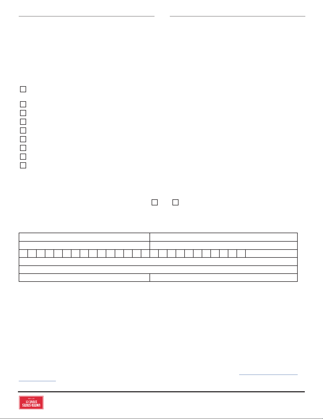
© 2021 United States Stove Company
3
LISTE DE CONTRÔLE D’INSTALLATION
S’il te plaît imprime
Nom du client: Numéro de Téléphone
Adresse:
Modèle:
Numéro de série:
Nom de la société d’installation: Numéro de Téléphone:
Nom du technicien d’installation: Numéro de Licence:
Votre poêle à bois ne doit être installé que par un installateur qualifié. Un installateur qualifié NFI peut être trouvé à www.nficertified.
org/public/find-an-nfi-pro/
ASSISTANCE TECHNIQUE
1-800-750-2723 poste 5050
Texte au 423-301-5624
Envoyez un e-mail à: customerservice@usstove.com
LISTE DE CONTRÔLE DE MISE EN SERVICE
Cette liste de contrôle doit être remplie intégralement par la personne qualifiée qui installe cet appareil. Conservez cette page pour
référence future.
Le fait de ne pas installer et mettre en service selon les instructions du fabricant et de remplir cette liste de contrôle annulera la
garantie.
DESCRIPTION DU TRAVAIL
Emplacement de l’appareil installé: ___________________________________________________________________________________________
Système de cheminée: nouveau système de cheminée
Oui Non si oui, marque ______________________________________
Si non, date d’inspection du système de cheminée existant: ____________________________________________________________________
MISE EN SERVICE
Confirmer l’installation du tapis de foyer conformément aux instructions d’installation ...............................................................................
Confirmer le bon placement des pièces internes ..........................................................................................................................................................
Vérifier la solidité du joint de porte et de l’étanchéité de la porte ............................................................................................................................
Confirmer les dégagements aux combustibles selon les instructions d’installation de ce manuel ..............................................................
Vérifier le fonctionnement des commandes pneumatiques .....................................................................................................................................
Confirmer que tous les tuyaux de fumée et le système de cheminée sont sécurisés et scellés ....................................................................
Confirmez que le poêle tire correctement lorsqu’il est allumé .................................................................................................................................
Assurez-vous qu’un avertisseur de CO est installé conformément aux codes du bâtiment locaux et qu’il est fonctionnel .................
Expliquer le fonctionnement en toute sécurité, l’utilisation appropriée du carburant, le nettoyage et les exigences d’entretien
courant .......................................................................................................................................................................................................................................
Déclaration d’achèvement: En tant que personne qualifiée responsable des travaux ci-dessus, je confirme que l’appareil en tant que
travail associé a été installé conformément aux instructions du fabricant et en suivant les codes de construction et d’installation
applicables.
Signé: _____________________________________________ Nom en lettres moulées ____________________________ Date: ________________
Propriétaire du domicile: CONSERVEZ CETTE INFORMATION POUR RÉFÉRENCE FUTURE
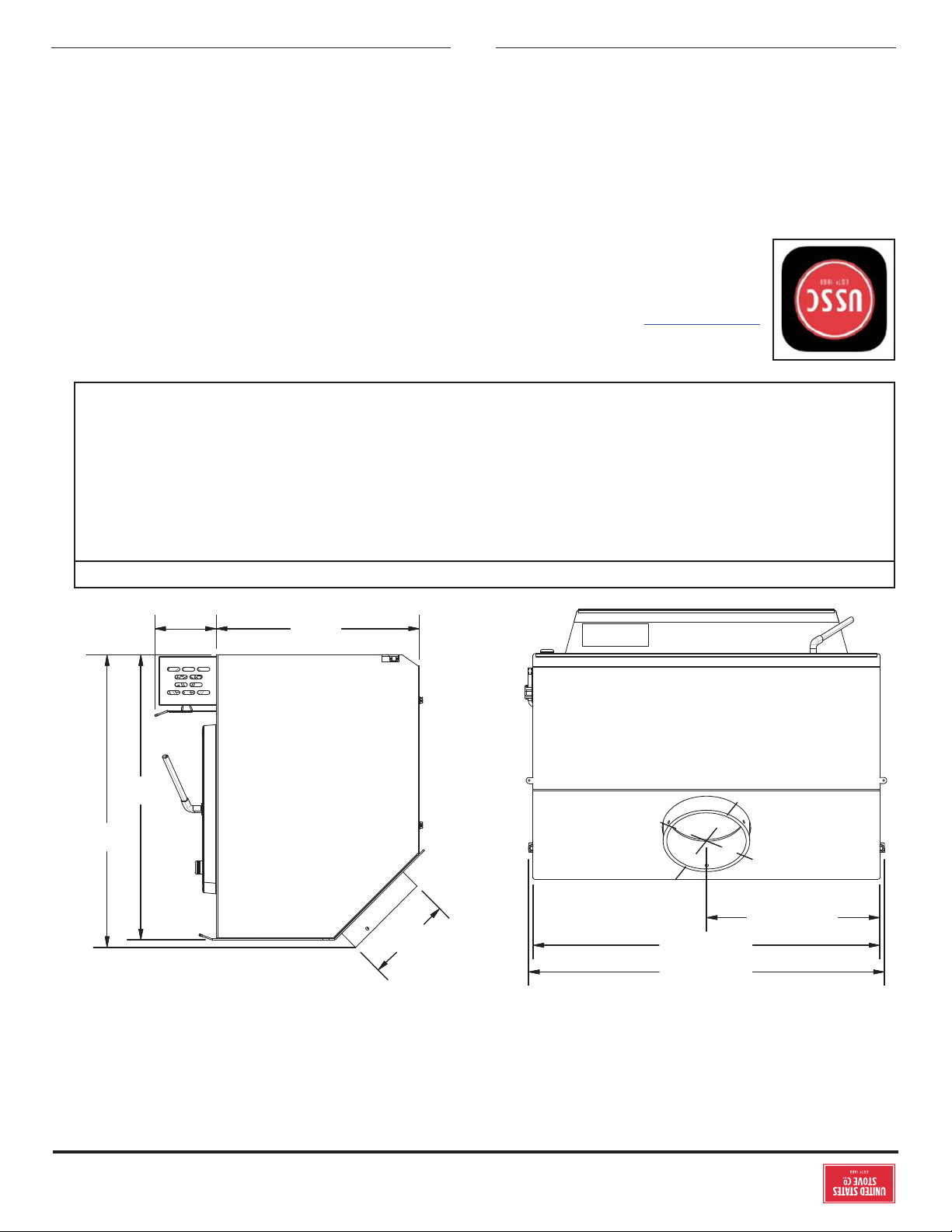
2
© 2021 United States Stove Company
Les instructions relatives à l’installation de votre poêle à bois sont conformes aux normes UL 1482-2011 (R2015) et ULC-628-93.
Ce manuel décrit l’installation et l’utilisation du chauage au bois USSC, US1800E. Ce poêle est conforme aux limites d’émissions de
bois imposées par la US Environmental Protection Agency pour les poêles à bois vendus après le 15 mai 2020. Dans des conditions
de test spécifiques, il a été démontré que ce poêle produisait de la chaleur à des débits allant de 9 487 à 33 050 Btu / h (* 1,8 g / h
et une ecacité de 65,5%). Remarque: Les cotes de BTU mentionnées ci-dessus sont basées sur le protocole de test de l’EPA sur le
bois d’oeuvre dimensionné doublement dimensionnel Nos BTU annoncés sont basés sur la première heure de fonctionnement avec
du bois de chauage brûlant à un taux de combustion élevé.pas être supérieure à 5-8 cm.
27-1/8” (691 mm)
26-1/2” (673 mm)
13-1/4” (337 mm)
6.1”
(155 mm)
21-3/4”
(553 mm)
22-3/8”
(568 mm)
15-1/2”
(394 mm)
4-11/16”
(119 mm)
AVERTISSEMENTS:
• CHAUD DURANT LE FONCTIONNEMENT. MAINTENEZ LES ENFANTS, LES VÊTEMENTS ET LE MOBILIER ÉLOIGNÉS.
TOUT CONTACT PEUT ENTRAÎNER DES BRÛLURES.
• N’UTILISEZ PAS DE PRODUITS CHIMIQUES NI DE FLUIDES POUR DÉMARRER LE FEU.
• NE LAISSEZ PAS LE POÊLE SANS SURVEILLANCE LORSQUE LA PORTE EST LÉGÈREMENT OUVERTE.
• NE BRÛLEZ PAS DE DÉCHETS NI DE FLUIDES INFLAMMABLES TELS QUE L’ESSENCE, LE NAPTHA OU L’HUILE POUR
MOTEUR.
• NE CONNECTEZ PAS LE POÊLE À UN CONDUIT OU CIRCUIT DE DISTRIBUTION D’AIR.
• FERMEZ TOUJOURS LA PORTE APRÈS L’ALLUMAGE.
INTRODUCTION
Pour le service client, veuillez appeler:
1-800-750-2723 poste 5050 ou;
Texte au 423-301-5624 ou;
Écrivez-nous à:
customerservice@usstove.com
Remarque: enregistrez votre produit en ligne sur
www.usstove.com ou téléchargez l’application
gratuite dès aujourd’hui. Cette application est
disponible uniquement sur l’App Store pour iPhone
et iPad. Rechercher US Stove. Conservez votre reçu
avec vos dossiers pour toute réclamation.
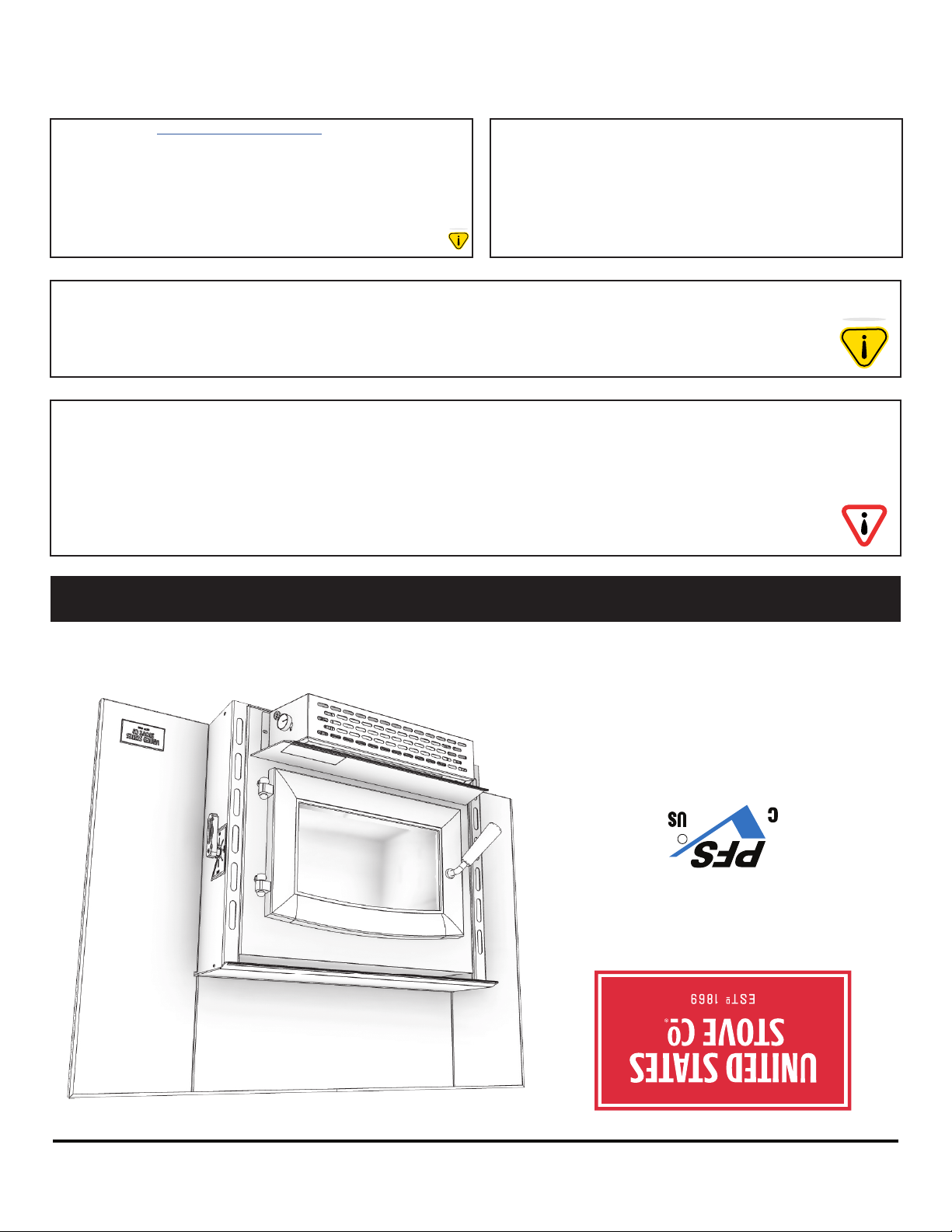
* Toutes les images de ce manuel sont à des fins d’illustration uniquement. Le produit réel peut varier.
© 2021 United States Stove Company, 227 Industrial Park Rd., South Pittsburg, TN 37380 Ph. 800-750-2723
CE MANUEL EST SUJET À MODIFICATION SANS PRÉAVIS.
Manuel d’instructions et d’utilisation du propriétaire
AGENCE AMÉRICAINE DE PROTECTION
DE L’ENVIRONNEMENT
Certifié conforme aux normes d’émissions
de particules 2020.
AVIS DE SÉCURITÉ: Si ce radiateur n’est pas correctement installé, un incendie peut en
résulter. Pour votre sécurité, suivez les instructions d’installation. N’utilisez jamais de
compromis de fortune lors de l’installation de ce radiateur. Contactez les responsables locaux
du bâtiment ou des pompiers pour connaître les permis, les restrictions et les exigences
d’installation dans votre région. NE JAMAIS UTILISER CE PRODUIT SANS SURVEILLANCE.
MISE EN GARDE! Veuillez lire l’intégralité de ce manuel avant d’installer ou d’utiliser votre
nouveau radiateur. Le non-respect des instructions peut entraîner des dommages matériels,
des blessures corporelles ou même la mort. Une installation incorrecte pourrait annuler votre
garantie!
Conservez ces instructions dans un endroit sûr pour référence ultérieure.
AVERTISSEMENT SUR LA PROPOSITION 65 DE LA
CALIFORNIE:
Ce produit peut vous exposer à des produits chimiques, y compris
le monoxyde de carbone, qui est connu dans l’État de Californie
pour provoquer le cancer, des anomalies congénitales et / ou
d’autres troubles de la reproduction. Pour plus d’informations,
visitez www.P65warnings.ca.gov
Numéro De Modèle:
US1800E
Testé selon les méthodes EPA ALT-125, ASTM
E2515, ASTM E3053 et CSA B415
Certifié: UL 1482-2011 (R2015), ULC-628-93
N’utilisez pas cet appareil dans un mobile home, une
maison préfabriquée, une caravane ou une tente.
R
Rapport No: F19-552