Loading ...
Loading ...
Loading ...
8
SUPPLIER GRADE
BP Enerpar SE100
Conoco Pale Paraffi n 22
Mobile D.T.E. Oil Light
G & G Oil Circulating 22
Imperial Oil Voltesso-35
Shell Canada Transformer-10
Texaco Diala-Oil-AX
Woco Premium 100
E-1 SHAFT SEAL SERVICE:
Disconnect power, remove screws and lockwashers, and
vertically lift motor assembly from body. Clean out body if
necessary. Clean and examine impeller for pitting or wear.
The impeller is threaded onto the shaft and to remove,
unscrew impeller, holding shaft with a large screwdriver.
CAUTION: - Handle seal parts with extreme care. DO
NOT scratch or mar lapped surfaces.
To expose shaft seal (1) disassemble volute and
impeller as outlined in above paragraph. Remove
rotating member (1b) from shaft (See Fig. 4). Examine all
seal parts and especially contact faces. Inspect seal for
signs of wear such as uneven wear pattern on stationary
members, chips and scratches on either seal face. DO
NOT interchange seal components, replace the entire
shaft seal (1). If replacing seal, remove stationary (1a) by
prying out with fl at screw driver.
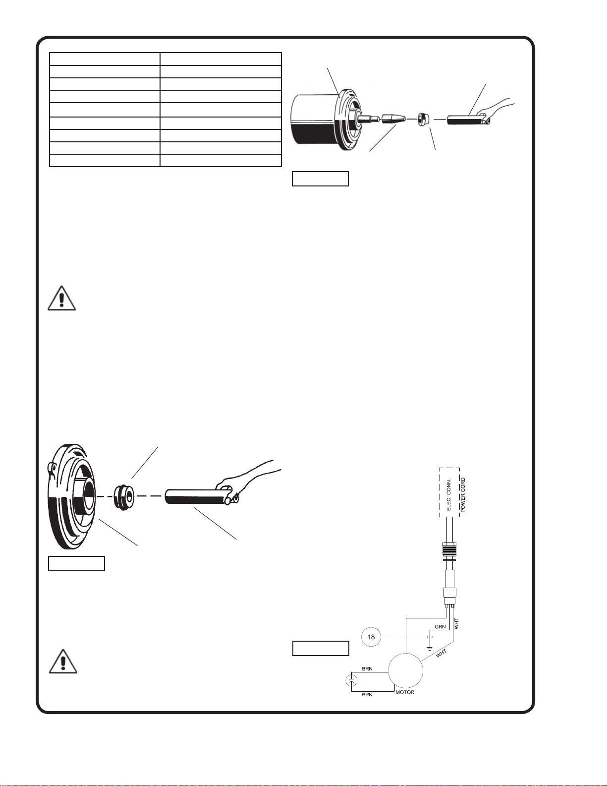
Clean and oil seal cavities in lower motor housing. Lightly
oil (DO NOT use grease) outer surface of stationary
member (1a). Press stationary member (1a) fi rmly into
lower motor housing, using a seal pusher, nothing but the
seal pusher is to come in contact with seal face (See Fig. 5).
IMPORTANT ! - DO NOT hammer on the seal pusher- it
will damage the seal face.
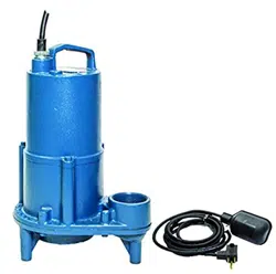
Make sure the stationary member is in straight. Slide a
bullet (see parts list-seal tool kit) over motor shaft. Lightly
oil (DO NOT use grease) shaft, bullet and inner surface of
bellows on rotating member (1b) See Fig. 6. With lapped
surface of rotating member (1b) facing inward toward
stationary member (1a), slide rotating member (1b) over
bullet and onto shaft, using seal pusher, until lapped faces
of (1a) and (1b) are together (See Fig. 4).
It is extremely important to keep seal faces clean during
assembly. Dirt particles lodged between these faces will
cause the seal to leak. Place spring (1b) over shaft and in
place on rotating member (1c), making sure it is seated.
Slide retaining ring (1a) over shaft and let rest on spring
(1b).
Before installing impeller, inspect threads on shaft and
impeller to assure that they are clean. Apply a thread-
locking compound to shaft threads and screw impeller
onto shaft and tighten. Rotate impeller to check for
binding. Install motor housing assembly on pump body.
Apply thread locking compound to each cap screw, thread
into body with lockwashers, and torque to 11 ft. lbs. Check
for free rotation of impeller. Assemble impeller and volute
replace oil
SECTION: F REPLACEMENT PARTS
Seal Pusher
Lower Motor Housing
Stationary Member
(1d) Polished Face Out
Rotating Member
(1c)
Motor & Lower Motor
Housing
Bullet
Seal Pusher
FIGURE 5
FIGURE 6
SINGLE PHASE - 115 VOLTS
MANUAL & AUTOMATIC
FIGURE 7
Loading ...
Loading ...
Loading ...