Loading ...
Loading ...
Loading ...
5
SECTION B: GENERAL INFORMATION
B-1) To The Purchaser:
Congratulations! You are the owner of one of the fi nest
pumps on the market today. Barnes® Pumps are products
engineered and manufactured of high quality components.
Over one hundred years of pump building experience
along with a continuing quality assurance program com-
bine to produce a pump which will stand up to the toughest
applications.
Check local codes and requirements before installation.
Servicing should be performed by knowledgeable pump
service contractors or authorized service stations.
The pump is packaged ready for installation and no con-
nections or adjustments are necessary except for attaching
discharge piping and plugging in service cord.
B-2) Receiving:
Upon receiving the pump, it should be inspected for dam-
age or shortages. If damage has occurred, fi le a claim
immediately with the company that delivered the pump.
If the manual is removed from the crating, do not lose or
misplace.
B-3) Storage:
Short Term- Barnes Pumps are manufactured for effi cient
performance following long inoperative periods in storage.
For best results, pumps can be retained in storage, as
factory assembled, in a dry atmosphere with constant
temperatures for up to six (6) months.
Long Term- Any length of time exceeding six (6) months,
but not more than twenty four (24) months. The units
should be stored in a temperature controlled area, a roofed
over walled enclosure that provides protection from the
elements (rain, snow, wind blown dust, etc..), and whose
temperature can be maintained between +40 deg. F and
+120 deg. F. Pump should be stored in its original shipping
container and before initial start up, rotate impeller by hand
to assure seal and impeller rotate freely.
B-4) Service Centers:
For the location of the nearest Barnes Service Center,
check your Barnes representative or Crane Pumps
& Systems, Inc., Service Department in Piqua, Ohio,
telephone (937) 778-8947 or Crane Pumps & Systems
Canada, Inc., Bramton, Ontario, (905) 457-6223.
SECTION C: INSTALLATION
C-1) Location:
These pumping units are self-contained and are
recommended for use in a sump or basin. The sump or
basin shall be vented in accordance with local plumbing
codes. This pump is designed to pump effl uent or
wastewater, nonexplosive and noncorrosive liquids and
shall NOT be installed in locations classifi ed as hazardous
in accordance with the National Electrical Code (NEC),
ANSI/NFPA 70 or the Canadian Electrical Code. Never
install the pump in a trench, ditch, or hole with a dirt
bottom; the legs will sink into the dirt and the suction will
become plugged.
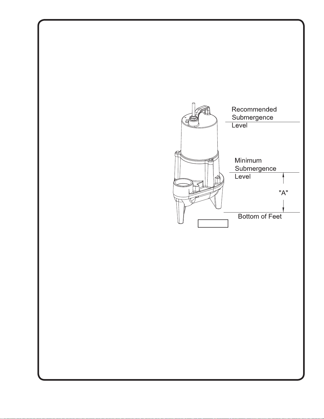
C-1.1) Submergence:
The pump should always be operated in the submerged
condition. The minimum sump liquid level should never be
less than A Dimension, A = 6.50 inches on SEV Series and
A=4.50 inches on EHV Series above the pump bottom.
The recommended level should not drop below the top of
the motor housing (see Fig. 1).
C-2) Discharge:
Discharge piping should be as short as possible. Both a
check valve and a shut-off valve are recommended for
each pump being used. The check valve is used to prevent
backfl ow into the sump. Excessive backfl ow can cause
fl ooding and/or damage to the pump. The shut-off valve
is used to stop system fl ow during pump or check valve
servicing.
C-3) Liquid Level Controls
Figure 2 shows a typical installation for any submersible
pump using a level control mounted to the discharge piping
with a piggy-back plug.
General Comments:
1) Never work in the sump with the power on.
2) Level controls are factory set for a pumping differential
of 9 inches. If that is the cycle desired, simply circle the
discharge pipe with the pipe mounting strap, feed the
end through the worm drive, and tighten with a
screwdriver. Be certain that the level control cannot
hang up or foul in its swing. Also, make certain the
pump impeller is still submerged when the level control
is in the “OFF” mode.
FIGURE 1
Loading ...
Loading ...
Loading ...