
Owner's Manual
[RI:IFTSMANo
20.5 HP
ELECTRIC START
42" MOWER
AUTOMATIC
LAWN TRACTOR
Model No.
917.270861
• Safety
•Assembly
• Operation
• Maintenance
• Repair Parts
CAUTION:
Read and follow all Safety Rules
and Instructions before operat-
ing this equipment.
For answers to your questions
about this product, Call:
1-800-659'5917
Sears Craftsman Help Line
5 am- 5 pm, Mon- Sat
Sears, Roebuck and Co., Hoffman Estates, 11.60179
Visit our Craftsman website:www.sears,com/craftsman
Warranty ............................................... 2
Safety Rules .......................... :.............. 2
Product Specifications .......................... 5
Assembly .............................................. 8
Operation ............................................ 11
Maintenance Schedule ...................... 18
Maintenance ....................................... 18
Service and Adjustments .................... 22
Storage ............................................... 28
Troubleshooting ................................. 29
Repair Parts ........................................ 34
Parts Ordering ..................... Back Cover
LIMITED TWO YEAR WARRANTY ON CRAFTSMAN RIDING EQUIPMENT
For two (2) years from the date of purchase, if this Craftsman Riding Equipment is
maintained, lubricated and tuned up according to the instructions in the owner's
manual, Sears will repair or replace, free of charge, any parts found to be defective in
material or workmanship.
This Warranty does not cover:
• Expendable items which become worn during normal use, such as blades, spark
plugs, air cleaners, belts, etc.
• Tire replacement or repair caused by punctures from outside objects, such as nails,
thorns, stumps, or glass.
• Repairs necessary because of operator abuse, negligence, improper storage or
accident or the failure to maintain the equipment according to the instructions
contained in the owner's manual.
• Riding equipment used for commercial or rental purposes.
LIMITED 90 DAY WARRANTY ON BA]-I-ERY
For ninety (90) days from date of purchase, if any battery included with this riding
equipment proves defective in material or workmanship and our testing determines the
battery will not hold a charge, Sears will replace the battery at no charge. In-home
warranty service on your Craftsman riding equipment is available at no charge for 30
days from the date of purchase. Please contact your nearest service center. After 30
days from the date of purchase, warranty service is available by taking your Craftsman
riding equipment to your nearest Sears Service Center. (In-home warranty service will
still be available after 30 days from the date of purchase but a standard trip charge will
apply). This warranty applies only while this product is in the United States. This
Warranty gives you specific legal rights, and you may also have other rights which may
vary from state to state.
Sears, Roebuck and Co., D/817 WA, Hoffman Estates, IL 60179
IMPORTANT: This cutting machine is
capable of amputating hands and feet
and throwing objects. Failure to observe
the following safety instructions could •
result in serious injury or death.
GENERAL OPERATION
• Read, understand, and follow all
instructions in the manual and on the
machine before starting.
• Only allow responsible adults, who are
familiar with the instructions, to
operate the machine.
2
Clear the area of objects such as
rocks, toys, wire, etc., which could be
picked up and thrown by the blade.
Be sure the area is clear of other
people before mowing. SLop machine
if anyone enters the area.
Never carry passengers.
Do not mow in reverse unless abso-
lutely necessary. Always look down
and behind before and while backing.
Be aware of the mower discharge
direction and do not point it at anyone.
Do not operate the mower without
either the entire grass catcher or the
guard in place.
• Slow down before turning.
• Never leave a running machine
unattended. Always turn off blades, set
parking brake, stop engine, and
remove keys before dismounting.
• Turn off blades when not mowing.
• Stop engine before removing grass
catcher or unclogging chute.
• Mow only in daylight or good artificial
light.
• Do not operate the machine while
under the influence of alcohol or
drugs.
• Watch for traffic when operating near
or crossing roadways.
• Use extra care when loading or
unloading the machine into a trailer or
truck.
SLOPE OPERATION
Slopes are a major factor related to loss-
of-control and tipover accidents, which
can result in severe injury or death. All
slopes require extra caution. If you
cannot back up the slope or if you feel
uneasy on it, do net mow it.
DO:
• Mow up and down slopes, not across.
• Remove obstacles such as rocks, tree
limbs, etc.
• Watch for holes, ruts, or bumps.
Uneven terrain could overturn the
machine. Tall grass can hide ob-
stacles.
• Use slow speed. Choose a low gear
so that you will not have to stop or shift
while on the slope.
• Follow the manufacturer's recommen-
dations for wheel weights or counter-
weights to improve stability.
• Use extra care with grass catchers or
other attachments These can change
the stability of the machine.
• Keep all movement on the slopes slow
and gradual. Do not make sudden
changes in speed or direction.
• Avoid starting or stopping on a slope. If
tires lose traction, disengage the
blades and proceed slowly straight
down the slope.
DO NOT"
• Do not turn on slopes unless neces-
sary, and then, turn slowly and
gradually downhill, if possible.
• Do not mow near drop-offs, ditches, or
embankments. The mower could
suddenly turn over if a wheel is over
the edge of a cliff or ditch, or if an edge
caves in.
• Do not mow on wet grass. Reduced
traction could cause sliding.
• Do nottry to stabilize the machine by
putting your foot on the ground.
• Do not use grass catcher on steep
slopes.
CHILDREN
Tragic accidents can occur if the operator
is not alert to the presence of children.
Children are often attracted to the
machine and the mowing activity. Never
assume that children will remain where
you last saw them,
• Keep children out of the mowing area
and under the watchful care of another
responsible adult.
• Be alert and turn machine off if
children enter the area
• Before and when backing, look behind
and down for small children.
• Never carry children. They may fall off
and be seriously injured or interfere
with safe machine operation.
• Never allow children to operate the
machine.
• Use extra care when approaching
blind corners, shrubs, trees, or other
objects that may obscure vision.
SERVICE
• Use extra care in handling gasoline
and other fuels. They are flammable
and vapors are explosive.
- Use only an approved container.
- Never remove gas cap or add fuel
with the engine running. Allow
engine to cool before refueling. Do
not smoke.
- Never refuel the machine indoors.
- Never store the machine or fuel
container inside where there is an
open flame, such as a water heater.
• Never run a machine inside a closed
area.
• Keep nuts and bolts, especially blade
attachment bolts, tight and keep
equipment in good condition,
• Never tamper with safety devices.
Check their proper operation regularly.
3
• Keep machine free of grass, leaves, or
other debris build-up. Clean oil or fuel
spillage. Allow machine to cool before
storing.
• Stop and inspect the equipment if you
strike an object. Repair, if necessary,
before restarting.
• Never make adjustments Or repairs
with the engine running.
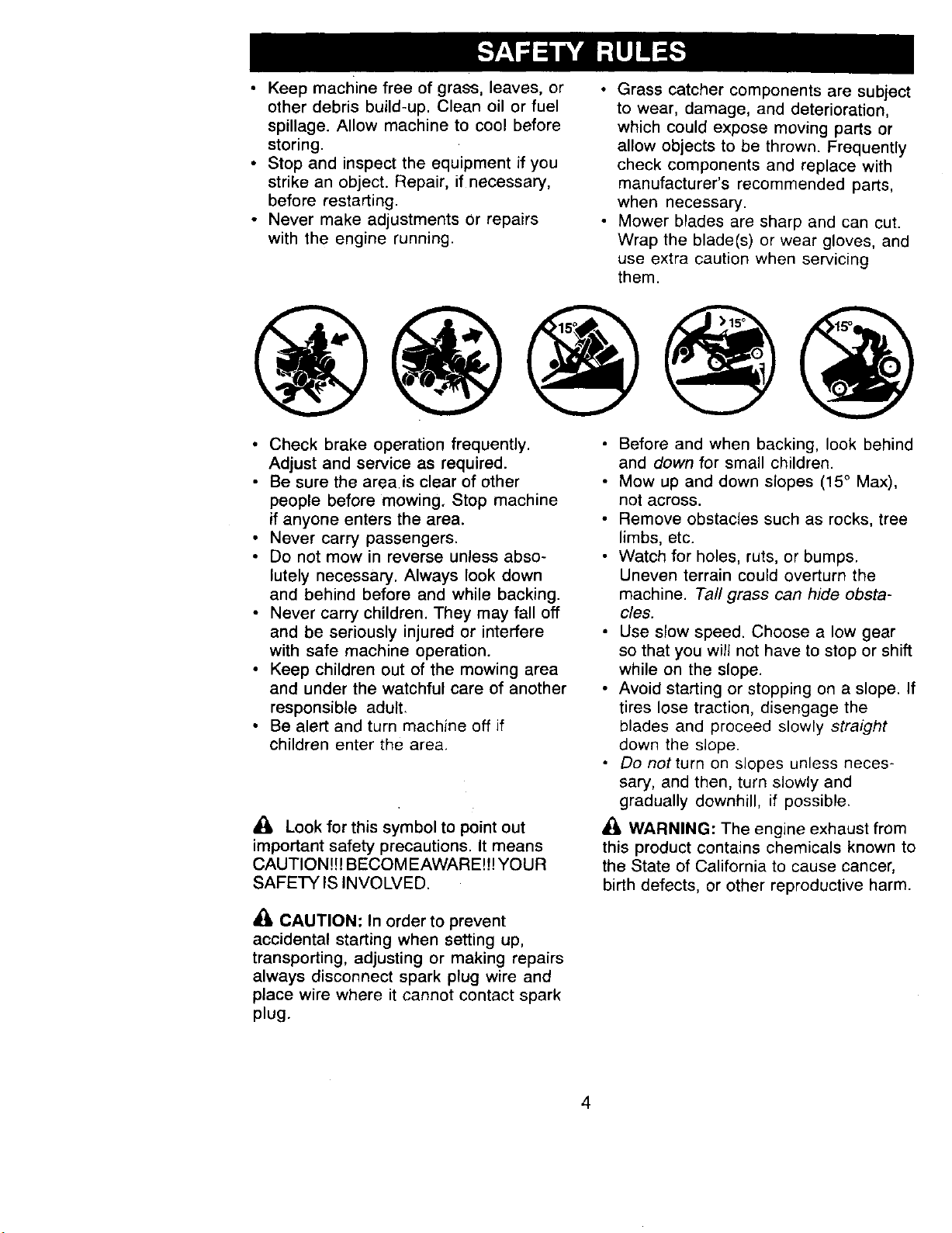
• Grass catcher components are subject
to wear, damage, and deterioration,
which could expose moving parts or
allow objects to be thrown. Frequently
check components and replace with
manufacturer's recommended parts,
when necessary.
• Mower blades are sharp and can cut.
Wrap the blade(s) or wear gloves, and
use extra caution when servicing
them.
@@@@@
• Check brake operation frequently.
Adjust and service as required.
• Be sure the area is clear of other
people before mowing, Stop machine
if anyone enters the area.
• Never carry passengers.
• Do not mow in reverse unless abso-
lutely necessary. Always look down
and behind before and while backing.
• Never carry children. They may fall off
and be seriously injured or interfere
with safe machine operation.
• Keep children out of the mowing area
and under the watchful care of another
responsible adult.
• Be alert and turn machine off if
children enter the area.
Look for this symbol to point out
important safety precautions. It means
CAUTION!!! BECOM EAWARE!7! YOUR
SAFETY IS INVOLVED.
d_ CAUTION: In order to prevent
accidental starting when setting up,
transporting, adjusting or making repairs
always disconnect spark plug wire and
place wire where it cannot contact spark
plug.
• Before and when backing, look behind
and down for small children.
• Mow up and down slopes (15 ° Max),
not across.
• Remove obstacles such as rocks, tree
limbs, etc.
• Watch for holes, ruts, or bumps.
Uneven terrain could overturn the
machine. Tall grass can hide obsta-
cles.
• Use slow speed. Choose a low gear
so that you will not have to stop or shift
while on the slope.
• Avoid starting or stopping on a slope. If
tires lose traction, disengage the
blades and proceed slowly straight
down the slope•
Do not turn on slopes unless neces-
sary, and then, turn slowly and
gradually downhill, if possible.
WARNING: The engine exhaust from
this product contains chemicals known to
the State of California to cause cancer,
birth defects, or other reproductive harm.
4
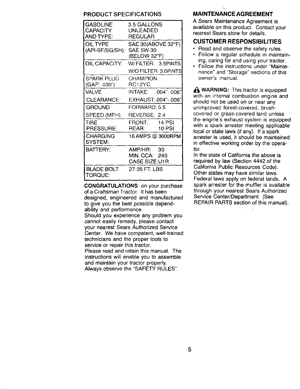
PRODUCT SPECIFICATIONS
GASOLINE
CAPACITY
AND TYPE:
OILTYPE
API-SF/SG/SH):
OIL CAPACITY:
!SPARK PLUG:
I(GAP: .030")
'VALVE
CLEARANCE:
GROUND
SPEED (MPH):
TIRE
PRESSURE:
CHARGING
SYSTEM:
BA'I-I-ERY: AMP/HR: 30
MIN. CCA: 240
CASE SIZE:U1R
BLADE BOLT 27-35 FT. LBS
TORQUE:
3.5 GALLONS
UNLEADED
REGULAR
SAE 30(ABOVE 32°F
SAE 5W-30
(BELOW 32°F)
W/FILTER: 3.5PINTS
W/O FILTER: 3.0PINTS
CHAMPION
RC12YC
INTAKE: .004"-.006"
EXHAUST:.004"-.006'
FORWARD: 5.5
REVERSE: 2.4
FRONT: 14 PSI
REAR: 10 PSI
16 AMPS @ 3600RPM
CONGRATULATIONS on your purchase
of a Craftsman Tractor. It has been
designed, engineered and manufactured
to give you the best possible depend-
ability and performance.
Should you experience any problem you
cannot easily remedy, please contact
your nearest Sears Authorized Service
Center. We have competent, well-trained
technicians and the proper tools to
service or repair this tractor.
Please read and retain this manual. The
instructions will enable you to assemble
and maintain your tractor properly.
Always observe the "SAFETY RULES".
MAINTENANCEAGREEMENT
A Sears Maintenance Agreement is
available on this product. Contact your
nearest Sears store for details.
CUSTOMER RESPONSIBILITIES
• Read and observe the safety rules.
• Follow a regular schedule in maintain-
ing, caring for and using your tractor.
• Follow the instructions under "Mainte-
nance" and "Storage" sections of this
owner's manual.
WARNING: This tractor is equipped
with an internal combustion engine and
should not be used on or near any
unimproved forest-covered, brush-
covered or grass-covered land unless
the engine's exhaust system is equipped
with a spark arrester meeting applicable
local or state laws (if any). If a spark
arrester is used, it should be maintained
in effective working order by the opera-
tor.
In the state of California ihe above is
required by law (Section 4442 of the
California Public Resources Code).
Other states may have similar laws.
Federal laws apply on federal lands. A
spark arrester for the muffler is available
through your nearest Sears Authorized
Service Center/Department (See
REPAIR PARTS section of this manual).
5
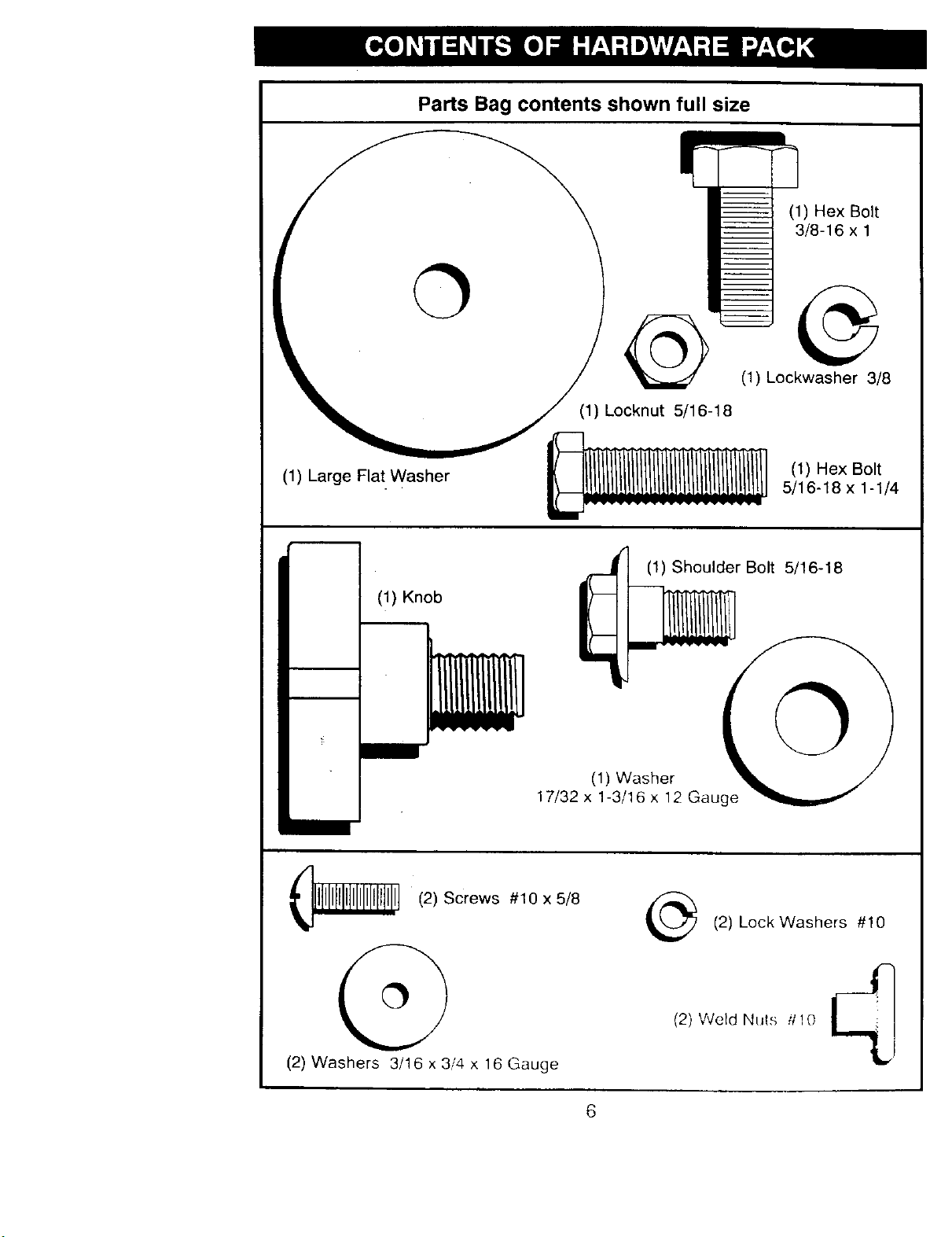
Parts Bag contents shown full size
I_/,exBol * '
3/8-16 x 1
k "_--_ / _ (1)Lockwasher 3/8
(1) Locknut 5/16-1 8
(1) Large Flat Washer [l_ii[1L _ (1)Hex Bolt
_11 III 5/16-18 x 1-1/4
/
(1) Knob
N
rJ (1) Shoulder Bolt 5/16-18
17/32x1-3/16x12Gauge _
I_ _ (2)Screws #10x5/8
(2) Washers 3/16x3i4x16Gauge
(2) Lock Washers #10
J7
ii ;
(2) Weld Nuts i110 _'_l i I
6
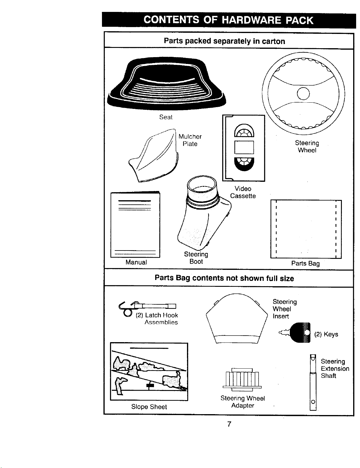
Parts packed separately in carton
Seat
Mulcher
Plate
_F
EC]
Steering
Wheel
Video
Cassette
Manual
Steering
Boot
I
I '
Parts Bag
Parts Bag contents not shown full size
(2) Latch Hook
Assemblies
S*eer,n41111
Wheel
Insert
(2) Keys
Slope Sheet
n I_ n
Steering Wheel
Adapter
Steering
Extension
Shaft
7
Your new tractor has been assembled at the factory with exception of those parts left
unassembled for shipping purposes. To ensure safe and proper operation of your
tractor all parts and hardware you assemble must be tightened securely. Use the
correct tools as necessary to insure proper tightness. Review the video cassette before
you begin.
TOOLS REQUIRED FOR ASSEMBLY
A socket wrench set will make assembly
easier. Standard wrench sizes you need
are listed below.
(1) 9/16"wrench (1) Pliers
(2) 1/2" wrench (1) Utility knife
(1) 3/4" socket with
drive ratchet
(1) Tire pressure gauge
(1) Phillips screwdriver
When right or left hand is mentioned in
this manual, it means, from your point of
view, when you are in the operating
position (seated behind the steering
wheel).
TO REMOVE TRACTOR FROM
CARTON
UNPACK CARTON
• Remove all accessible loose parts and
parts boxes from shipping carton
• Cut, from top to bottom, along lines on
all four corners of shipping carton, and
lay panels flat
• Remove mower and packing materi-
als.
• Check for any additional loose parts or
boxes and remove.
BEFORE ROLLING TRACTOR OFF
SKID
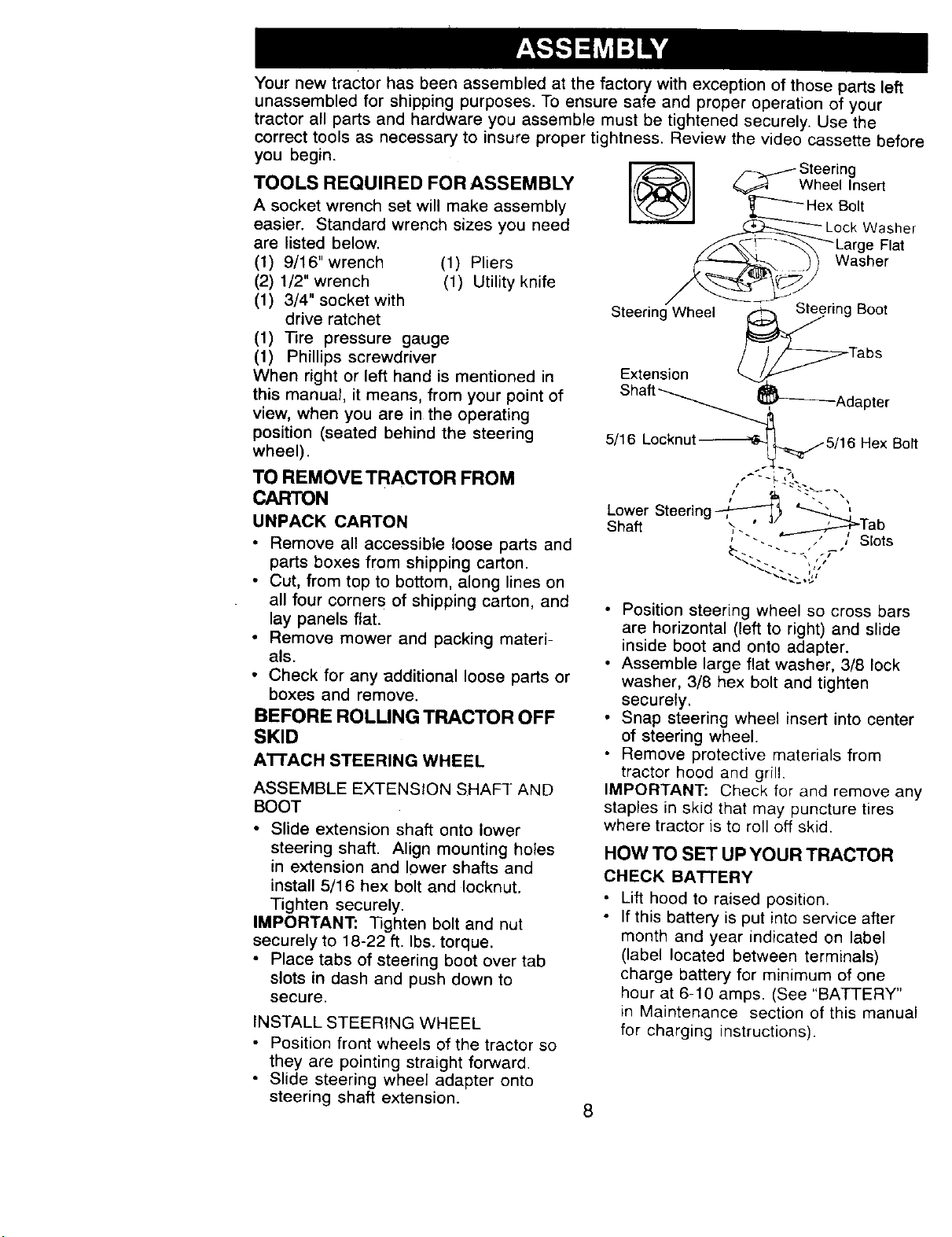
A'B'ACH STEERING WHEEL
ASSEMBLE EXTENSION SHAFT AND
BOOT
• Slide extension shaft onto lower
steering shaft. Align mounting holes
in extension and lower shafts and
install 5/16 hex bolt and Iocknut.
Tighten securely.
IMPORTANT: 13ghten bolt and nut
securely to 18-22 ft. Ibs. torque.
• Place tabs of steering boot over tab
slots in dash and push down to
secure.
INSTALL STEERING WHEEL
• Position front wheels of the tractor so
they are pointing straight forward.
• Slide steering wheel adapter onto
steering shaft extension.
Steering
Wheel Insert
ex Bolt
LCkrgeW_:_;t r
Washer
Steering Wheel Steering Boot
Extension _/
Shaft _.
5/16 Locknut _
Tabs
}'_Adapter
_.,--5/16 Hex Bolt
Lower Steering _ I
Shah :..' !ab
"-. , _ SEots
• Position steering wheel so cross bars
are horizontal (left to right) and slide
inside boot and onto adapter.
• Assemble large flat washer, 3/8 lock
washer, 3/8 hex bolt and tighten
securely.
• Snap steering wheel insert into center
of steering wheel.
• Remove protective materials from
tractor hood and grill.
IMPORTANT: Check for and remove any
staples in skid that may puncture tires
where tractor is to roll off skid.
HOW TO SET UP YOUR TRACTOR
CHECK BATTERY
• Lift hood to raised position.
• If this battery is put into service after
month and year indicated on label
(label located between terminals)
charge battery for minimum of one
hour at 6-10 amps. (See "BATTERY"
in Maintenance section of this manual
for charging instructions).
8
• Label
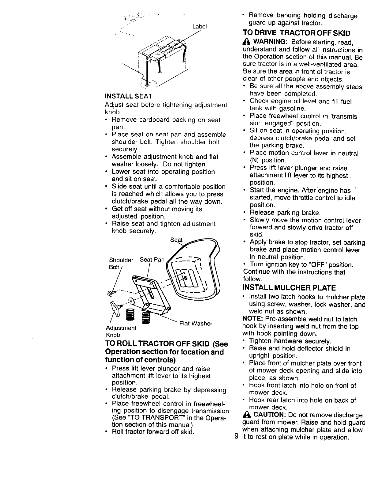
INSTALLSEAT
Adjust seat before tightening adjustment
knob.
• Remove cardboard packing on seat
pan.
• Place seat on seat pan and assemble
shoulder bolt. Tighten shoulder bolt
securely.
• Assemble adjustment knob and flat
washer loosely. Do not tighten.
• Lower seat into operating position
and sit on seat.
• Slide seat until a comfortable position
is reached which allows you to press
clutch/brake pedal all the way down.
• Get off seat without moving its
adjusted position.
• Raise seat and tighten adjustment
knob securely.
Seat
Shoulder Seat Pan
Bolt
Adjustment
Knob
TO ROLLTRACTOR OFF SKID (See
Operation section for location and
function of controls)
• Press lift lever plunger and raise
attachment lift lever to its highest
position.
• Release parking brake by depressing
clutch/brake pedal.
• Place freewheel control in freewheel-
ing position to disengage transmission
(See "TO TRANSPORT' in the Opera-
tion section of this manual).
• Roll tractor forward off skid.
• Remove banding holding discharge
guard up against tractor.
TO DRIVE TRACTOR OFF SKID
WARNING: Before starting, read,
understand and follow all instructions in
the Operation section of this manual. Be
sure tractor is in a well-ventilated area.
Be sure the area in front of tractor is
clear of other people and objects.
• Be sure all the above assembly steps
have been completed.
• Check engine oil level and fill fuel
tank with gasoline.
• Place freewheel control in 'transmis-
sion engaged" position.
• Sit on seat in operating position,
depress clutch/brake pedal and set
the parking brake.
• Place motion control lever in neutral
(N) position.
• Press lift lever plunger and raise
attachment lift lever to its highest
position.
• Start the engine. After engine has '
started, move throttle control to idle
position.
• Release parking brake.
• Slowly move the motion control lever
forward and slowly drive tractor off
skid.
• Apply brake to stop tractor, set parking
brake and place motion control lever
in neutral position.
• Turn ignition key to "OFF" position.
Continue with the instructions that
follow.
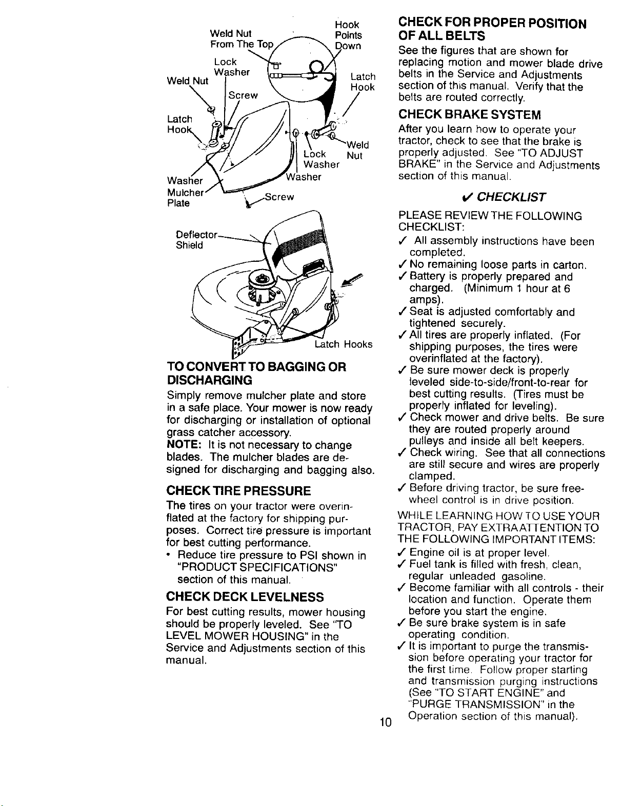
INSTALL MULCHER PLATE
• Install two latch hooks to mulcher plate
using screw, washer, lock washer, and
weld nut as shown.
NOTE: Pre-assemble weld nut to latch
hook by inserting weld nut from the top
with hook pointing down.
• Tighten hardware securely.
• Raise and hold deflector shield in
upright position.
• Place front of mulcher plate over front
of mower deck opening and slide into
place, as shown.
• Hook front latch into hole on front of
mower deck.
• Hook rear latch into hole on back of
mower deck.
A(_ CAUTION: Do not remove discharge
guard from mower. Raise and hold guard
when attaching mulcher plate and allow
9 it to rest on plate while in operation.
Weld Nut
From The T¢
Lock
Washer
Weld Nut
Latch
Hook_,
Washer
PlateMUlcher ',_f/Screw
Hook
Points
Latch
Hook
/
)ck Nut
Washer
Shield
Latch Hooks
TO CONVERT TO BAGGING OR
DISCHARGING
Simply remove mulcher plate and store
in a safe place. Your mower is now ready
for discharging or installation of optional
grass catcher accessory.
NOTE: It is not necessary to change
blades. The mulcher blades are de-
signed for discharging and bagging also.
CHECK TIRE PRESSURE
The tires on your tractor were overin-
flated at the factory for shipping pur-
poses. Correct tire pressure is important
for best cutting performance.
• Reduce tire pressure to PSI shown in
"PRODUCT SPECIFICATIONS"
section of this manual.
CHECK DECK LEVELNESS
For best cutting results, mower housing
should be properly leveled. See 'q-O
LEVEL MOWER HOUSING" in the
Service and Adjustments section of this
manual.
CHECK FOR PROPER POSITION
OF ALL BELTS
See the figures that are shown for
replacing motion and mower blade drive
belts in the Service and Adjustments
section of this manual. Verify that the
belts are routed correctly.
CHECK BRAKE SYSTEM
After you learn how to operate your
tractor, check to see that the brake is
properly adjusted. See "TO ADJUST
BRAKE" in the Service and Adjustments
section of this manual.
10
V" CHECKLIST
PLEASE REVIEWTHE FOLLOWING
CHECKLIST:
/ All assembly instructions have been
completed.
,/No remaining loose parts in carton.
,/Battery is properly prepared and
charged. (Minimum 1 hour at 6
amps).
,/Seat is adjusted comfortably and
tightened securely.
,/All tires are properly inf[ated. (For
shipping purposes, the tires were
everinflated at the factory).
•/ Be sure mower deck is properly
leveled side-to-side/front-to-rear for
best cutting results. (Tires must be
properly inflated for leveling).
,/Check mower and drive belts. Be sure
they are routed properly around
pulleys and inside all belt keepers.
/ Check wiring. See that all connections
are still secure and wires are properly
clamped.
/ Before driving tractor, be sure free-
wheel control is in drive position.
WHILE LEARNING HOW TO USE YOUR
TRACTOR. PAY EXTRAAT[ENTION TO
THE FOLLOWING IMPORTANT ITEMS:
J" Engine oil is at proper level.
,/Fuel tank is filled with fresh, clean,
regular unleaded gasoline.
,/Become familiar with all controls - their
location and function. Operate them
before you start the engine.
,/Be sure brake system is in safe
operating condition.
•/ It is important to purge the transmis-
sion before operating your tractor for
the first time. Follow proper starting
and transmission purging instructions
(See "TO START ENGINE" and
"PURGE TRANSMISSION" in the
Operation section of this manual).
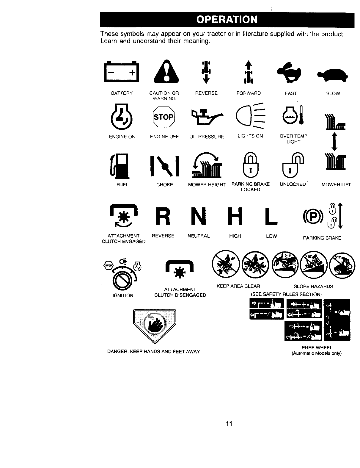
Thesesymbolsmayappearonyourtractororin literaturesuppliedwiththeproduct.
Learnandunderstandtheir meaning.
BATTERY CAUTION OR
WARNING
REVERSE FORWARD FAST SLOW
ENGINE ON ENGINE OFF OIL PRESSURE
FUEL CHOKE MOWER HEIGHT
LIGHTS ON
®
PARKING BRAKE
LOCKED
OVI_TEMPI
UNLOCKED MOWER LIFT
N H L
ATTACHMENT REVERSE NEUTRAL HIGH LOW PARKING BRAKE
CLUTCH ENGAGED
ATTACHMENT KEEP AREA CLEAR SLOPE HAZARDS
IGNITION CLUTCH DISENGAGED
DANGER, KEEP HANDS AND FEET AWAY
(SEE SAFETY RULES SECTION)
FREE WHEEL
(Automatic Models only)
11
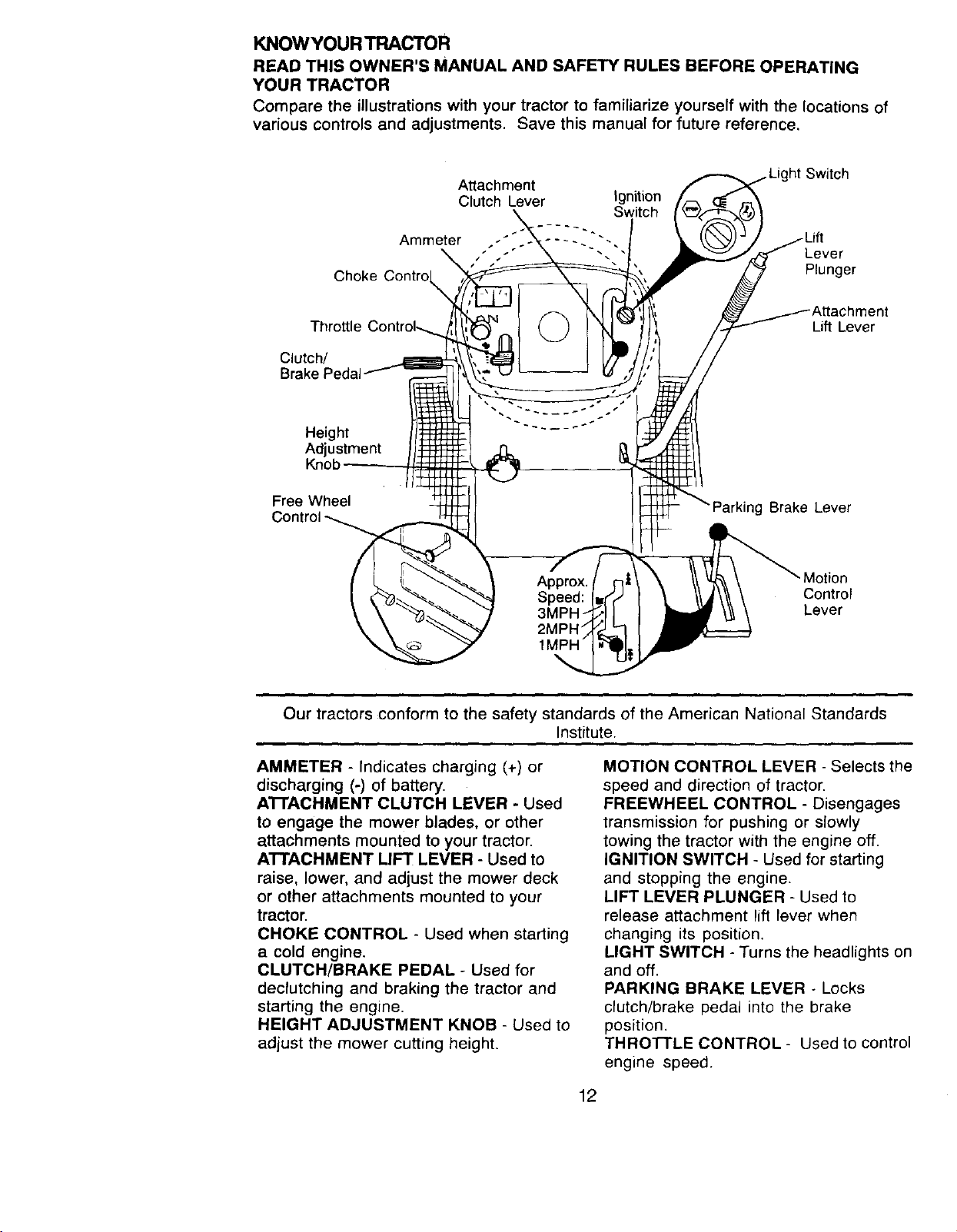
KNOWYOUR TRACTOR
READ THIS OWNER'S MANUAL AND SAFETY RULES BEFORE OPERATING
YOUR TRACTOR
Compare the illustrations with your tractor to familiarize yourself with the locations of
various controls and adjustments. Save this manual for future reference,
Attachment
Clutch Lever
Ammeter
Choke Contro
ignition
Switch
Switch
Lever
Plunger
Thro_le
Clutch/
Brake
Lift Lever
Height
Adjustment
Knob
Free Wheel
ig Brake Lever
Motion
Control
Lever
Our tractors conform to the safety standards of the American National Standards
Institute.
AMMETER - Indicates charging (+) or
discharging (-) of battery.
A'I-FACHMENT CLUTCH LEVER - Used
to engage the mower blades, or other
attachments mounted to your tractor.
ATTACHMENT LIFT LEVER - Used to
raise, lower, and adjust the mower deck
or other attachments mounted to your
tractor.
CHOKE CONTROL - Used when starting
a cold engine.
CLUTCH/BRAKE PEDAL - Used for
declutching and braking the tractor and
starting the engine.
HEIGHT ADJUSTMENT KNOB - Used to
adjust the mower cutting height.
MOTION CONTROL LEVER - Selects the
speed and direction of tractor.
FREEWHEEL CONTROL - Disengages
transmission for pushing or slowly
towing the tractor with the engine off.
IGNITION SWITCH - Used for starting
and stopping the engine.
LIFT LEVER PLUNGER - Used to
release attachment lift lever when
changing its position.
LIGHT SWITCH - Turns the headlights on
and off.
PARKING BRAKE LEVER - Locks
clutch/brake pedal into the brake
position.
THROTTLE CONTROL - Used to control
engine speed.
12
The operation of any tractor can result in foreign objects thrown into
the eyes, which can result in severe eye damage. Always wear safety
glasses or eye shields while operating your tractor or performing any
adjustments or repairs. We recommend a wide vision safety mask
over spectacles or standard safety glasses.
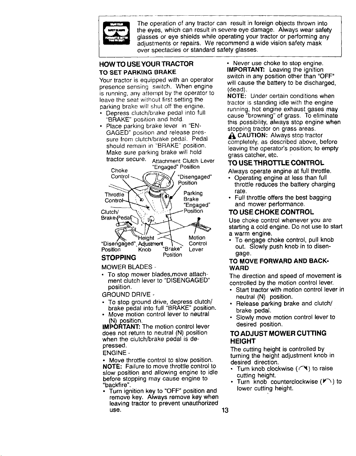
HOW TO USE YOUR TRACTOR
TO SET PARKING BRAKE
Your tractor is equipped with an operator
presence sensing switch. When engine
is running, any attempt by the operator to
leave the seat without first setting the
parking brake will shut off the engine.
• Depress clutch/brake pedal into full
"BRAKE" position and hold.
• Place parking brake lever in "EN-
GAGED" position and release pres-
sure from clutch/brake pedal. Pedal
should remain in "BRAKE" position.
Make sure parking brake will hold
tractor secure. Attachment Clutch Lever
Choke "Engaged" Position
'-
Position
STOPPING
"Disengaged"
Position
/
Parking
Brake
"Engaged"
.------Position
Motion
Control
Knob "Brake" Lever
Position
MOWER BLADES -
• To stop mower blades,move attach-
ment clutch lever to "DISENGAGED"
position.
GROUND DRIVE -
• To stop ground drive, depress clutch/
brake pedal into full "BRAKE" position.
• Move motion control lever to neutral
(N) position.
IMPORTANT: The motion control lever
does not return to neutral (N) position
when the clutch/brake pedal is de-
pressed.
ENGINE -
• Move throttle control to slow position.
NOTE: Failure to move throttle control to
slow position and allowing engine to idle
before stopping may cause engine to
"backfire".
• Turn ignition key to "OFF" position and
remove key. Always remove key when
leaving tractor to prevent unauthorized
use.
• Never use choke to stop engine.
IMPORTANT: Leaving the ignition
switch in any position other than "OFF"
will cause the battery to be discharged,
(dead).
NOTE: Under certain conditions when
tractor is standing idle with the engine
running, hot engine exhaust gases may
cause "browning" of grass. To eliminate
this possibility, always stop engine when
stopping tractor on grass areas.
CAUTION: Always stop tractor
completely, as described above, before
leaving the operator's position; to empty
grass catcher, etc.
TO USE THROTTLE CONTROL
Always operate engine at full throttle.
• Operating engine at less than full
throttle reduces the battery charging
rate.
• Full throttle offers the best bagging
and mower performance.
TO USE CHOKE CONTROL
Use choke control whenever you are
starting a cold engine. Do not use to start
a warm engine.
• To engage choke control, pull knob
out. Slowly push knob in to disen-
gage.
TO MOVE FORWARD AND BACK-
WARD
The direction and speed of movement is
controlled by the motion control lever,
• Start tractor with motion control lever ir
neutral (N) position.
Release parking brake and clutch/
brake pedal.
• Slowly move motion control lever to
desired position.
TO ADJUST MOWER CUFFING
HEIGHT
The cutting height is controlled by
turning the height adjustment knob in
desired direction.
• Turn knob clockwise (¢-_1) to raise
cutting height.
• Turn knob counterclockwise (_-'_)to
lower cutting height.
13
The cutting height range is approxi-
mately 1-1/2" to 4". The heights are
measured from the ground to the blade
tip with the engine not runnirig. These
heights are approximate and may vary
depending upon soil conditions, height
of grass and types of grass being
mowed.
• The average lawn should be cut to
approximately 2-1/2 inches during the
cool season and to over 3 inches
during hot months, For healthier and
better looking lawns, mow often and
after moderate growth.
• For best cutting performance, grass
over 6 inches in height should be
mowed twice. Make the first cut
relatively high; the second to desired
height.
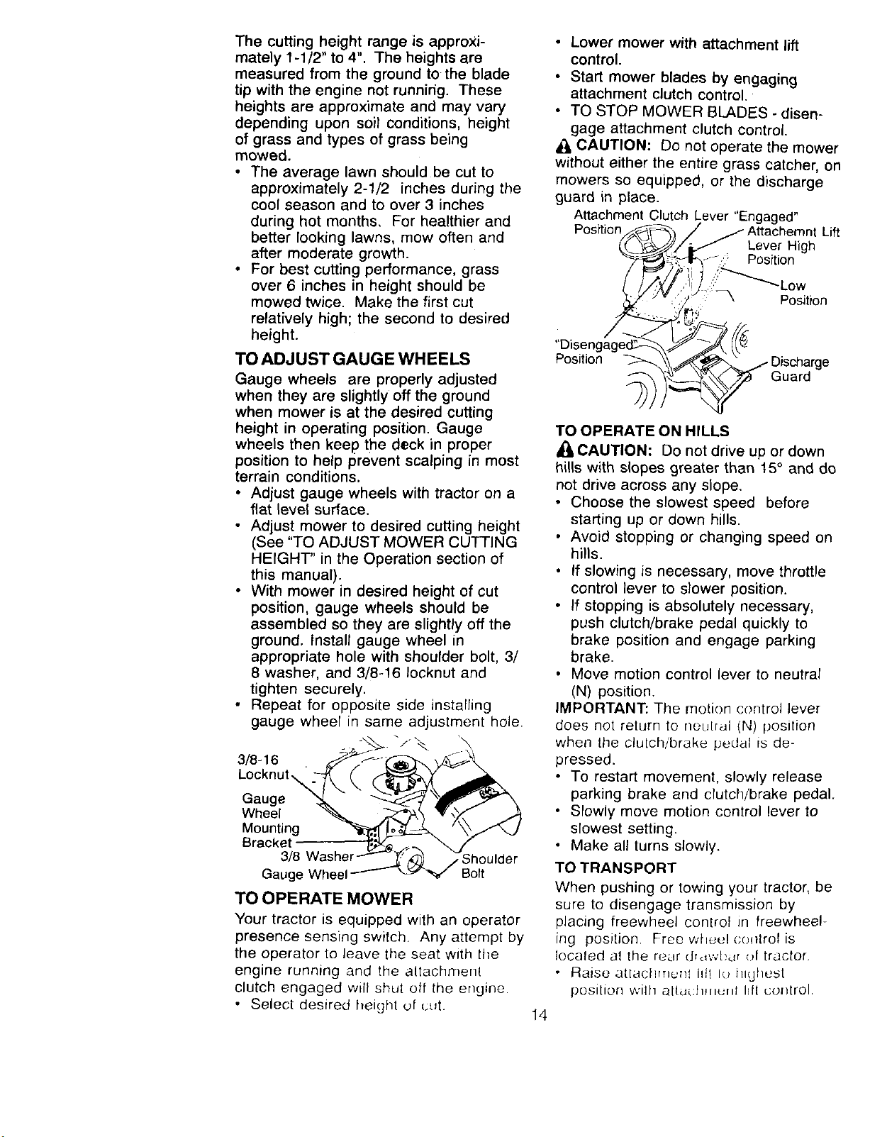
TO ADJUST GAUGE WHEELS
Gauge wheels are properly adjusted
when they are slightly off the ground
when mower is at the desired cutting
height in operating position. Gauge
wheels then keep the deck in proper
position to help prevent scalping in most
terrain conditions.
• Adjust gauge wheels with tractor on a
flat level surface.
• Adjust mower to desired cutting height
(See "TO ADJUST MOWER CUTTING
HEIGHT" in the Operation section of
this manual),
• With mower in desired height of cut
position, gauge wheels should be
assembled so they are slightly off the
ground. Install gauge wheel in
appropriate hole with shoulder bolt, 3/
8 washer, and 3/8-16 Iocknut and
tighten securely.
• Repeat for opposite side installing
gauge wheel in same adjustment hole.
3/8-16
Locknut_
Gauge
Wheel
Mounting
Bracket
Gauge Wheel
_z/Shoulder
Bolt
TO OPERATE MOWER
Your tractor is equipped with an operator
presence sensing switch. Any attempt by
the operator to leave the seat with the
engine running and the altachment
clutch engaged will shut off the engine.
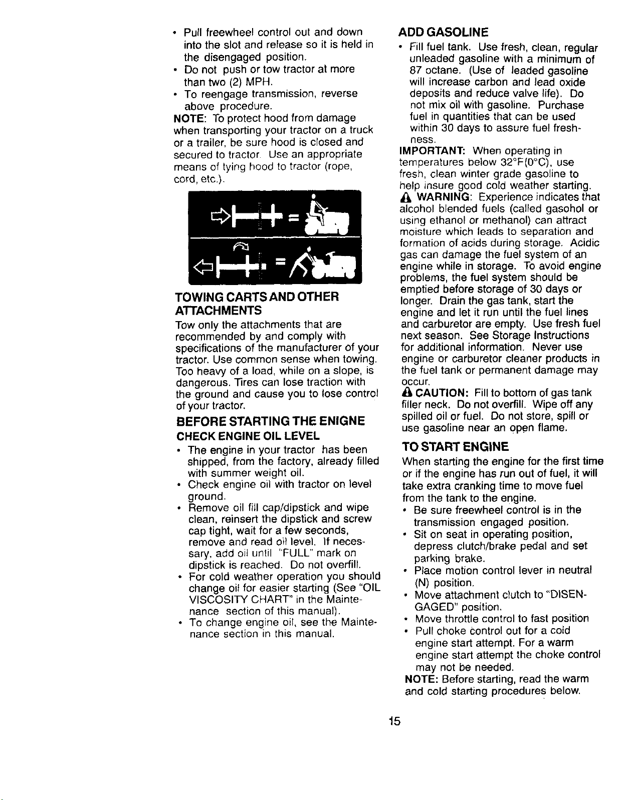
• Select desired height of cut.
• Lower mower with attachment lift
control.
• Start mower blades by engaging
attachment clutch control.
• TO STOP MOWER BLADES - disen-
gage attachment clutch control.
_, CAUTION: Do not operate the mower
without either the entire grass catcher, on
mowers so equipped, or the discharge
guard in place.
Attachment Clutch Lever "Engaged"
Position t Lift
Lever High
Position
f;i_Lo w
:' _ Position
Position
Guard
14
TO OPERATE ON HILLS
A_-CAUTION: Do not drive up or down
hills with slopes greater than 15° and do
not drive across any slope.
• Choose the slowest speed before
starting up or down hills.
• Avoid stopping or changing speed on
hills.
If slowing is necessary, move throttle
control lever to slower position.
• If stopping is absolutely necessary,
push clutch/brake pedal quickly to
brake position and engage parking
brake.
Move motion control lever to neutral
(N) position.
IMPORTANT: The motion control lever
does not return to netJtral (N) position
when the clutch/brake pedal is de-
pressed.
• To restart movement, slowly release
parking brake and clutch/brake pedal.
• Slowly move motJon control lever to
slowest setting.
• Make all turns slowly.
TO TRANSPORT
When pushing or towing your tractor, be
sure to disengage transmission by
placing freewheel control Jr] freewheel-
ing position. Free whuu! co+]trol is
focaled at the reur (Jrd;'./[)dr ()l tractor.
• Raise attachtHu_t idt I,._highest
posllion will] altuuhmutd hft col_trol.
• Pull freewheel control out and down
into the slot and release so it is held in
the disengaged position.
• Do not push or tow tractor at more
than two (2) MPH.
• To reengage transmission, reverse
above procedure.
NOTE: To protect hood from damage
when transporting your tractor on a truck
or a trailer, be sure hood is closed end
secured to tractor. Use an appropriate
means of tying hood to tractor (rope,
cord, etc.).
TOWING CARTS AND OTHER
ATTACHMENTS
Tow only the attachments that are
recommended by and comply with
specifications of the manufacturer of your
tractor. Use common sense when towing.
Too heavy of a load, while on a slope, is
dangerous. Tires can lose traction with
the ground and cause you to lose control
of your tractor.
BEFORE STARTING THE ENIGNE
CHECK ENGINE OIL LEVEL
• The engine in your tractor has been
shipped, from the factory, already filled
with summer weight oil.
• Check engine oil with tractor on level
ground.
• Remove oil fill cap/dipstick and wipe
clean, reinsert the dipstick and screw
cap tight, wait for a few seconds,
remove and read oil level. If neces-
sary, add oil until "FULL" mark on
dipstick is reached. Do not overfill.
• For cold weather operation you should
change oil for easier starting (See "OIL
VISCOSITY CHART" in the Mainte-
nance section of this manual).
• To change engine oil, see the Mainte-
nance section in this manual.
ADDGASOLINE
• Fill fuel tank. Use fresh, clean, regular
unleaded gasoline with a minimum of
87 octane. (Use of leaded gasoline
will increase carbon and lead oxide
deposits and reduce valve life). Do
not mix oil with gasoline. Purchase
fuel in quantities that can be used
within 30 days to assure fuel fresh-
ness.
IMPORTANT: When operating in
temperatures below 32°F(0°C), use
fresh, clean winter grade gasoline to
help insure good cold weather starting.
_, WARNING: Experience indicates that
alcohol blended fuels (called gasohol or
using ethanol or methanol ) can attract
moisture which leads to separation and
formation of acids during storage. Acidic
gas can damage the fuel system of an
engine while in storage. To avoid engine
problems, the fuel system should be
emptied before storage of 30 days or
longer. Drain the gas tank, start the
engine and let it run until the fuel lines
and carburetor are empty. Use fresh fuel
next season. See Storage Instructions
for additional information. Never use
engine or carburetor cleaner products in
the fuel tank or permanent damage may
Occur.
CAUTION: Fill to bottom of gas tank
filler neck. Do not overfill. Wipe off any
spilled oil or fuel. Do not store, spill or
use gasoline near an open flame.
TO START ENGINE
When starting the engine for the first time
or if the engine has run out of fuel, it will
take extra cranking time to move fuel
from the tank to the engine.
• Be sure freewheel control is in the
transmission engaged position,
° Sit on seat in operating position,
depress clutch/brake pedal and set
parking brake.
• Place motion control lever in neutral
(N) position.
• Move attachment clutch to "DISEN-
GAGED" position.
Move throttle control to fast position
• Pull choke Control out for a cold
engine start attempt. For a warm
engine start .attempt the choke control
may net be needed.
NOTE: Before starting, read the warm
and cold starting procedure s below.
15
• Insert key into ignition and turn key
clockwise to "START" position and
release key as soon as engine starts.
Do not run starter continuously for
more than fifteen seconds per minute.
If the engine does not start after
several attempts, push choke control
in, wait a few minutes and try again, if
engine still does not start, pull the
choke control out and retry.
WARM WEATHER STARTING (50 ° F and
above)
• When engine starts, slowly push
choke control in until the engine
begins to run smoothly. If the engine
starts to run roughly, pull the choke
control out slightly for a few seconds
and then continue to push the control
in slowly.
• The attachments and ground drive can
now be used. if the engine does not
accept the load, restart the engine and
allow it to warm up for one minute
using the choke as described above.
COLD WEATHER STARTING (50 ° F and
below)
• When engine starts, slowly push
choke controt in until the engine
begins to run smoothly. Continue to
push the choke control in small steps
allowing the engine to accept small
changes in speed and load, until the
choke control is fully in. if the engine
starts to run roughly, pull the choke
control out slightly for a few seconds
and then continue to push the control
in slowly. This may require an engine
warm-up period from several seconds
to several minutes, depending on the
temperature.
AUTOMATIC TRANSMISSION WARM UP
• Before driving the unit in cold weather,
the transmission should be warmed up
as follows:
• Be sure the tracior is on level
ground.
• Place the motion control lever in
neutral. Release the parking brake
and let the clutch/brake
slowly return to operating position.
• Allow one minute for transmission to
warm up. This can be done during
the engine warm up period.
• The attachments can be used during
the engine warm-up period after the
transmission has been warmed up
and may require the choke control be
pulled out slightly.
NOTE: if at a high altitude (above 3000
feet) or in cold temperatures (below 32
F) the carburetor fuel mixture may need
to be adjusted for best engine perfor-
mance. See "TO ADJUST CARBURE-
TOR" in the Service and Adjustments
section of this manual.
PURGE TRANSMISSION
CAUTION: Never engage or disen-
gage freewheel lever while the engine is
running.
To ensure proper operation and perfor-
mance, it is recommended that the
transmission be purged before operating
tractor for the first time. This procedure
will remove any trapped air inside the
transmission which may have developed
during shipping of your tractor.
IMPORTANT: Should your transmission
require removal for service or replace-
ment, it should be purged after reinstalla-
tion before operating the tractor.
• Place tractor safely on level surface
with engine off and parking brake set.
• Disengage transmission by placing
freewheel control in freewheeling
position (See "TO TRANSPORT" in
this section of manual).
• Sitting in the tractor seat, start engine.
After the engine is running, move
throttle control to slow position. With
motion control lever in neutral iN)
position, slowly disengage clutch/
brake pedal.
• Move motion control lever to full
forward position and ho_d for five (5)
seconds. Move lever to full reverse
position and hold for five (5) seconds.
Repeat this procedure three (3) times.
NOTE: During this procedure there will
be no movement of drive wheels. The air
is being removed from hydraulic drive
system.
• Move motion control lever to neutral
iN) position. Shut- oft engine and set
parking brake.
• Engage transmission by placing
freewheel control in driving position
(See "TO TRANSPORT" in this section
of manual).
16
• Sitting in the tractor seat, start engine.
After the engine is running, move
throttle control to half (1/2) speed. With
motion control lever in neutral (N)
position, slowly disengage clutch/
brake pedal.
• Slowly move motion control lever
forward, after the tractor moves
approximately five (5) feet, slowly
move motion control lever to reverse
position. After the tractor moves
approximately five (5) feet return the
motion control lever to the neutral (N)
position. Repeat this procedure with
the motion control lever three (3)
times.
• Your tractor is now purged and now
ready for normal operation.
MOWING TIPS
• Mower should be properly leveled for
best mowing performance. See "TO
LEVEL MOWER HOUSING" in the
Service and Adjustments section of
this manual.
• The left hand side of mower should be
used for trimming.
• Drive so that clippings are discharged
onto the area that has been cut. Have
the cut area to the right of the tractor.
This will result in a more even distribu-
tion of clippings and more uniform
cutting.
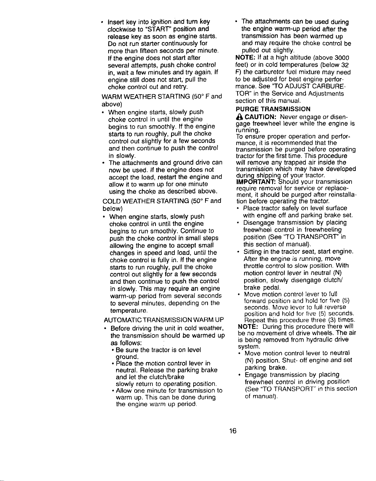
• When mowing large areas, start by
turning to the right so that clippings will
discharge away from shrubs, fences,
driveways, etc. After one or two
rounds, mow in the opposite direction
making left hand turns until finished.
• If grass is extremely tall, it should be
mowed twice to reduce load and
possible fire hazard from dried
clippings. Make first cut relatively
high; the second to the desired height.
• Do not mew grass when it is wet. Wet
grass will plug mower and leave
undesirable clumps. Allow grass to
dry before mowing.
• Always operate engine at full throttle
when mowing to assure better mowing
performance and proper discharge of
material. Regulate ground speed by
selecting a low enough gear to give
the mower cutting performance as well
as the quality of cut desired.
• When operating attachments, select a
ground speed that will suit the terrain
and give best performance of the
attachment being used.
f
1
MULCHING MOWING TIPS
IMPORTANT: For best performance,
keep mower housing free of built-up
grass and trash. Clean after each use.
• The special mulching blade will recut
the grass clippings many times and
reduce them in size so that as they fall
onto the lawn they will disperse into
the grass and not be noticed. Also, the
mulched grass will biodegrade quickly
to provide nutrients for the lawn.
Always mulch with your highest
engine (blade) speed as this will
provide the best recutting action of the
blades.
• Avoid cutting your lawn when it is wet.
Wet grass tends to form clumps and
interferes with the mulching action.
The best time to mow your lawn is the
early afternoon. At this time the grass
has dried and the newly cut area will
not be exposed to the direct sun.
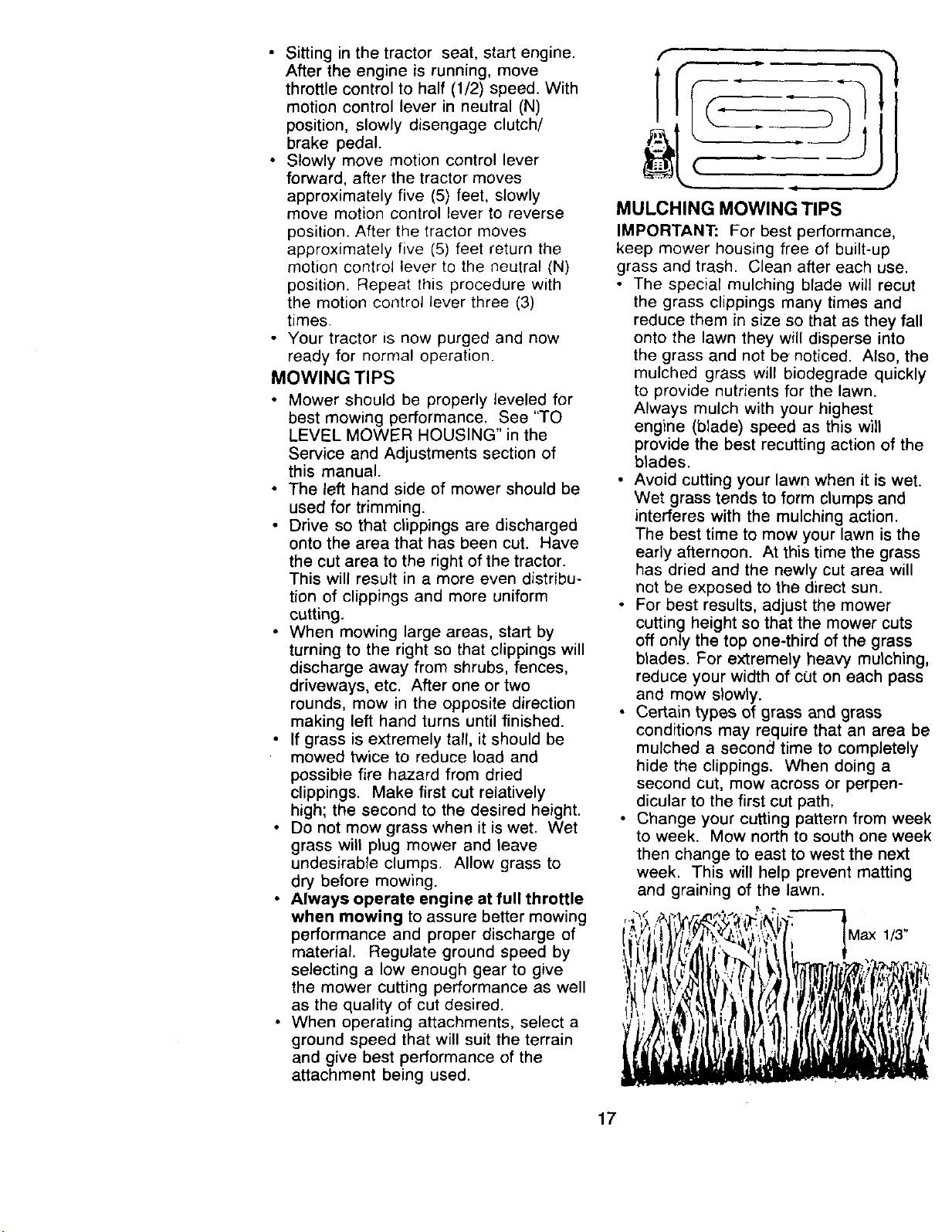
• For best results, adjust the mower
cutting height so that the mower cuts
off only the top one-third of the grass
blades. For extremely heavy mulching,
reduce your width of cut on each pass
and mow slowly.
• Certain types of grass and grass
conditions may require that an area be
mulched a second time to completely
hide the clippings. When doing a
second cut, mow across or perpen-
dicular to the first cut path,
• Change your cutting pattern from week
to week. Mow north to south one week
then change to east to west the next
week. This will help prevent matting
and graining of the lawn.
1/3"
17
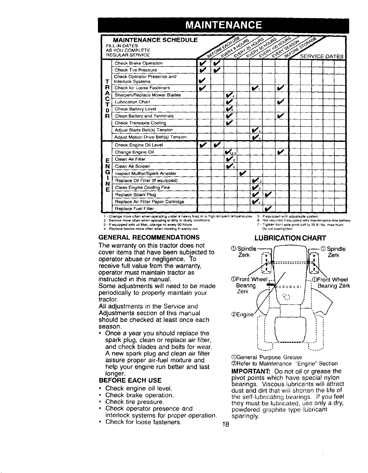
MAINTENANCE SCHEDULE _,_._/_/_ _,'_'_=_o'_ '_
i Check Brake Operation
Check Tire Pressure
Check Operator Presence and
T Interlock Systems
g Check for Loose Fasteners
A Sharpen/Replace Mower Blades
T Lubrication Chart
O Check Battery Level
a Clean Battery and Terminals
Cbeck Transaxle Cooling
Adjust Blade Belt(s) Tension
Adjust Motion Drive Belt(s) Tension
Check Engine Oil Level
Change Engine Oil
E i Clean Air Filter
N i Clean Air Screen
G Inspect Muffler/Spark Arrestor
N, Replace Oil Filter (If equipped)
Clean Engine Coo,ling Fins
Replace Spark Plug
Replace Air Filter Paper Cartridge
Replace Fuel Filter
v'
! Change more often when operating Under a heavy load or in hJgh ambient temperatures 5 If equipped wrth adiustable system
2 - Se p*,ice more orlon when o_eratlng it1 ditty or dusty conditions¸ 6. Not required Jf equlpped with maintenance.fl'ee batlery,
3 - If equipped with oil fi_er, change oil every, 50 hours • . Tighten front &xle pivot bob to 35 fl .Ibs maximum
4 - Rsplace blades more of_en whett mowing _n s_ldy soi_ De not overtighten
GENERAL RECOMMENDATIONS
The warranty on this tractor does not
cover items that have been subjected to
operator abuse or negligence. To
receive full value from the warranty,
operator must maintain tractor as
instructed in this manual.
Some adjustments will need to be made
periodically to properly maintain your
tractor.
All adjustments in the Service and
Adjustments section of this manual
should be checked at least once each
season.
• Once a year you should replace the
spark plug, clean or replace air filter,
and check blades and belts for wear,
A new spark plug and clean air filter
assure proper air-fuel mixture and
help your engine run better and last
longer.
BEFORE EACH USE
• Check engine oil level.
• Check brake operation.
• Check tire pressure.
• Check operator presence and
interlock systems for proper operation.
• Check for loose fasteners.
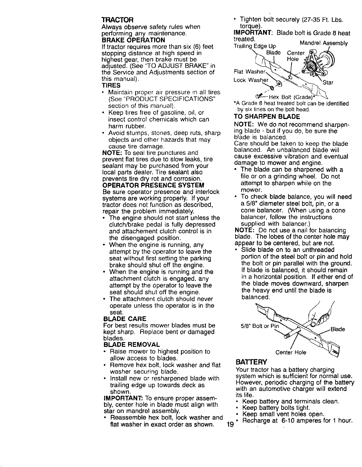
LUBRICATION CHART
Zerk Zerk
OFr0nt Wheel
Bearing
Zerk
Bearing Zerk
18
QGeneral Purpose Grease
@Refer to Maintenance "Engine" Section
IMPORTANT: Do not oil or grease the
pivot points which have special nylon
bearings. Viscous lubricants will attract
dust and dirt that will shorten the life of
the self-lubricating bearings. If you feel
they must be lubricated, use only a dry,
powdered graphite type lubricant
sparingly.
TRACTOR
Always observe safety rules when
performing any maintenance.
BRAKE OPERATION
If tractor requires more than six (6) feet
stopping distance at high speed in
highest gear, then brake must be ,
adjusted. (See "TO ADJUST BRAKE' in
the Service and Adjustments section of
this manual).
TIRES
• Maintain proper air pressure in all tires
(See "PRODUCT SPECIFICATIONS"
section of this manual).
• Keep tires free of gasoline, oil, or
insect control chemicals which can
harm rubber.
• Avoid stumps, stones, deep ruts, sharp
objects and other hazards that may
cause tire damage.
NOTE; To seal tire punctures and
prevent flat tires due to slow leaks, tire
sealant may be purchased from your
local parts dealer. Tire sealant also
prevents tire dry rot and corrosion.
OPERATOR PRESENCE SYSTEM
Be sure operator presence and interlock
systems are working properly. If your
tractor does not function as described,
repair the problem immediately.
• The engine should not start unless the
clutch/brake pedal is fully depressed
and attachement clutch control is in
the disengaged position.
• When the engine is running, any
attempt by the operator to leave the
seat without first setting the parking
brake should shut off the engine.
• When the engine is running and the
attachment clutch is engaged, any
attempt by the operator to leave the
seat should shut off the engine.
• The attachment clutch should never
operate unless the operator is in the
seat.
BLADE CARE
For best results mower blades must be
kept sharp. Replace bent or damaged
blades.
BLADE REMOVAL
• Raise mower to highest position to
allow access to blades.
• Remove hex bolt, lock washer and flat
washer securing blade.
• Install new or resharpened blade with
trailing edge up towards deck as
shown.
IMPORTANT: To ensure proper assem-
bly, center hole in blade must align with
star on mandrel assembly.
• Reassemble hex bolt, lock washer and
flat washer in exact order as shown.
• Tighten bolt securely (27-35 Ft. Lbs.
torque).
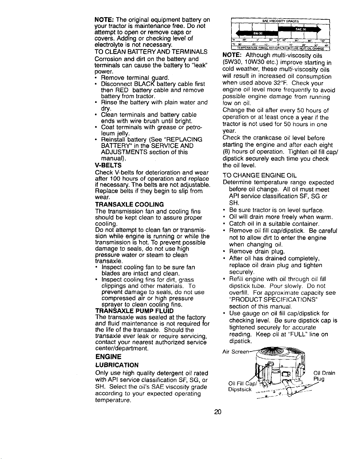
IMPORTANT: Blade bolt is Grade 8 heat
treated.
Mandrel Assembly
Trailing Edge Up
Blade Center
Hole
Flat Washer
Lock Washel
_---Hex Bolt (Grad_
*A Grade 8 heat treated bolt can be identified
by six lines on the bolt head.
TO SHARPEN BLADE
NOTE: We do not recommend sharpen-
ing blade - but if you do, be sure the
blade is balanced.
Care should be taken to keep the blade
balanced. An unbalanced blade will
cause excessive vibration and eventual
damage to mower and engine.
• The blade can be sharpened with a
file or on a grinding wheel. Do not
attempt to sharpen while on the
mower.
• To check blade balance, you will need
a 5/8" diameter steel bolt, pin, or a
cone balancer. (When using a cone
balancer, follow the instructions
supplied with balancer.)
NOTE: Do not use a nail for balancing
blade. The lobes of the center hole may
appear to be centered, but are not.
• Slide blade on to an unthreaded
portion of the steel bolt or pin and hold
the bolt or pin parallel with the ground.
If blade is balanced, it should remain
in a horizontal position. If either end of
the blade moves downward, sharpen
the heavy end until the blade is
balanced.
5/8" Boft_. _
...... _aoe
BATI'ERY
Your tractor has a battery charging
system which is sufficient for normal use.
However, periodic charging of the battery
with an automotive charger will extend
its life.
i Keep battery and terminals clean.
Keep battery bolts tight.
Keep small vent holes open.
19 ° Recharge at 6-10 amperes for 1 hour.
NOTE: The original equipment battery on
your tractor is maintenance free, Do not
attempt to open or remove caps or
covers. Adding or checking level of
electrolyte is not necessary.
TO CLEAN BATTERYAND TERMINALS
Corrosion and dirt on the battery and
terminals can cause the battery to "leak"
power.
• Remove terminal guard.
• Disconnect BLACK battery cable first
then RED battery cable and remove
battery from tractor.
• Rinse the battery with plain water and
dry.
• Clean terminals and battery cable
ends with wire brush until bright.
• Coat terminals with grease or petro-
leum jelly.
• Reinstall battery (See "REPLACING
BATTERY" in the SERVICE AND
ADJUSTMENTS section of this
manual).
V-BELTS
Check V-belts for deterioration and wear
after 100 hours of operation and replace
if necessary. The belts are not adjustable.
Replace belts if they begin to slip from
wear.
TRANSAXLE COOLING
The transmission fan and cooling fins
should be kept clean to assure proper
cooling.
Do not attempt to clean fan or transmis-
sion while engine is running or while the
transmission is hot. To prevent possible
damage to seals, do not use high
pressure water or steam to clean
transaxle.
Inspect cooling fan to be sure fan
blades are intact and clean.
Inspect cooling fins for dirt, grass
clippings and other materials. To
prevent damage to seals, do not use
compressed air or high pressure
sprayer to clean cooling fins.
TRANSAXLE PUMP FLUID
The transaxle was sealed at the factory
and fluid maintenance is not required for
the life of the transaxle. Should the
transaxle ever leak or require servicing,
contact your nearest authorized service
center/department.
ENGINE
LUBRICATION
Only use high quality detergent oil rated
with API service classification SF, SG, or
SH. Select the oil's SAE viscosity grade
according to your expected operating
temperature.
SAlE VISCOSITY GRADES
NOTE: Although multi-viscosity oils
(5W30, 10W30 etc.) improve starting in
cold weather, these multi-viscosity oils
will result in increased oil consumption
when used above 32°E Check your
engine oil level more frequently to avoid
possible engine damage from running
low on oil.
Change the oil after every 50 hours of
operation or at least once a year if the
tractor is not used for 50 hours in one
year.
Check the crankcase oil level before
starting the engine and after each eight
(8) hours of operation. Tighten oil fill cap/
dipstick securely each time you check
the oil level.
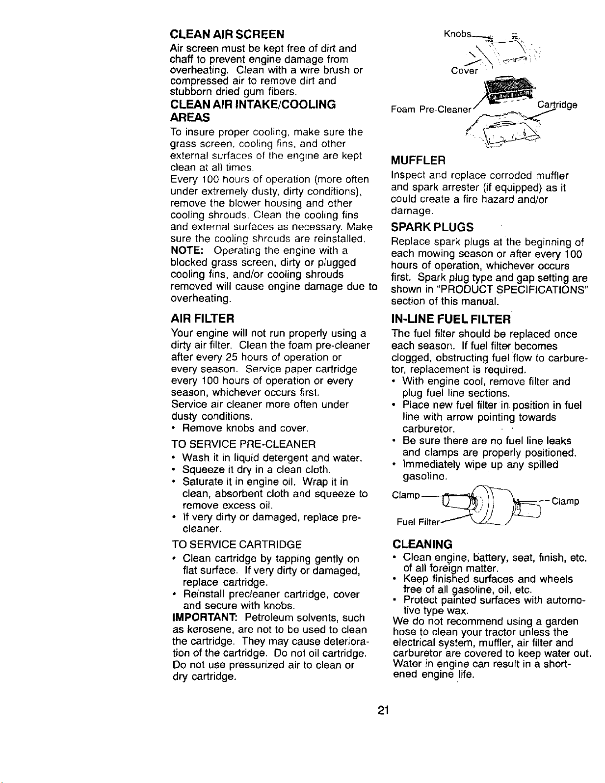
TO CHANGE ENGINE OIL
Determine temperature range expected
before oil change. All oil must meet
API service classification SF, SG or
SH.
• Be sure tractor is on level surface.
• Oil will drain more freely when warm.
• Catch oil in a suitable container.
• Remove oil fill cap/dipstick. Be careful
not to allow dirt to enter the engine
when changing oil.
• Remove drain plug.
• After oil has drained completely,
replace oil drain plug and tighten
securely.
• Refill engine with oil through oil fill
dipstick tube. Pour slowly. Do not
overfill. For approximate capacity see
"PRODUCT SPECIFICATIONS"
section of this manual.
• Use gauge on oil fill cap/dipstick for
checking level. Be sure dipstick cap is
tightened securely for accurate
reading. Keep oil at "FULL" line on
dipstick.
Air Scre_
Oil Drain
2O
CLEAN AIR SCREEN
Air screen must be kept free of dirt and
chaff to prevent engine damage from
overheating. Clean with a wire brush or
compressed air to remove dirt and
stubborn dried gum fibers.
CLEAN AIR INTAKE/COOLING
AREAS
To insure proper cooling, make sure the
grass screen, cooling fins, and other
external surfaces of tile engine are kept
clean at all times.
Every 100 hours of operation (more often
under extremely dusty, dirty conditions),
remove the blower housing and other
cooling shrouds. Clean the cooling fins
and external surfaces as necessary. Make
sure the cooling shrouds are reinstalled.
NOTE: Operating the engine with a
blocked grass screen, dirty or plugged
cooling fins, and/or cooling shrouds
removed will cause engine damage due to
overheating.
AIR FILTER
Your engine will not run properly using a
dirty air filter. Clean the foam pre-cleaner
after every 25 hours of operation or
every season. Service paper cartridge
every 100 hours of operation or every
season, whichever occurs first.
Service air cleaner more often under
dusty conditions.
• Remove knobs and cover.
TO SERVICE PRE-CLEANER
• Wash it in liquid detergent and water.
• Squeeze it dry in a clean cloth.
• Saturate it in engine oil. Wrap it in
clean, absorbent cloth and squeeze to
remove excess oil.
• If very dirty or damaged, replace pre-
cleaner.
TO SERVICE CARTRIDGE
• Clean cartridge by tapping gently on
flat surface. If very dirty or damaged,
replace cartridge.
• Reinstall precleaner cartridge, cover
and secure with knobs.
IMPORTANT: Petroleum solvents, such
as kerosene, are not to be used to clean
the cartridge. They may cause deteriora-
tion of the cartridge. Do not oil cartridge.
Do not use pressurized air to clean or
dry cartridge.
Kn°bs_s _ "
Cover
_Cartridge
Foam Pre-Cleaner .__..._,.=._...,_,f._
/ :
MUFFLER
Inspect and replace corroded muffler
and spark arrester (if equipped) as it
could create a fire hazard and/or
damage.
SPARK PLUGS
Replace spark plugs at the beginning of
each mowing season or after every 100
hours of operation, whichever occurs
first. Spark plug type and gap setting are
shown in "PRODUCT SPECIFICATIONS"
section of this manual.
IN-LINE FUEL FILTER
The fuel filter should be replaced once
each season. If fuel filter becomes
clogged, obstructing fuel flow to carbure-
tor, replacement is required.
• With engine cool, remove filter and
plug fuel line sections.
• Place new fuel filter in position in fuel
line with arrow pointing towards
carburetor.
• Be sure there are no fuel line leaks
and clamps are properly positioned.
• Immediately wipe up any spilled
gasoline.
Cl;u_lPF_ CIamp
CLEANING
• Clean engine, battery, seat, finish, etc.
of all foreign matter.
• Keep finished surfaces and wheels
free of all gasoline, oil, etc.
Protect painted surfaces with automo-
tive type wax.
We do not reCommend using a garden
hose to clean your tractor unless the
electrical system, muffler, air filter and
carburetor are covered to keep water out.
Water in engine can result in a short-
ened engine life.
21
4
_:_CAUTION: Before performing any service or adjustments:
Depress clutch/brake pedal fully and set parking brake.
Place motion control lever in neutral (N) position.
Place attachment clutch in "DISENGAGED" position.
Turn ignition key "OFF" and remove key.
Make sure the blades and all moving parts have completely stopped.
Disconnect spark plug wire from spark plug and place wire where it cannot
come in contact with plug.
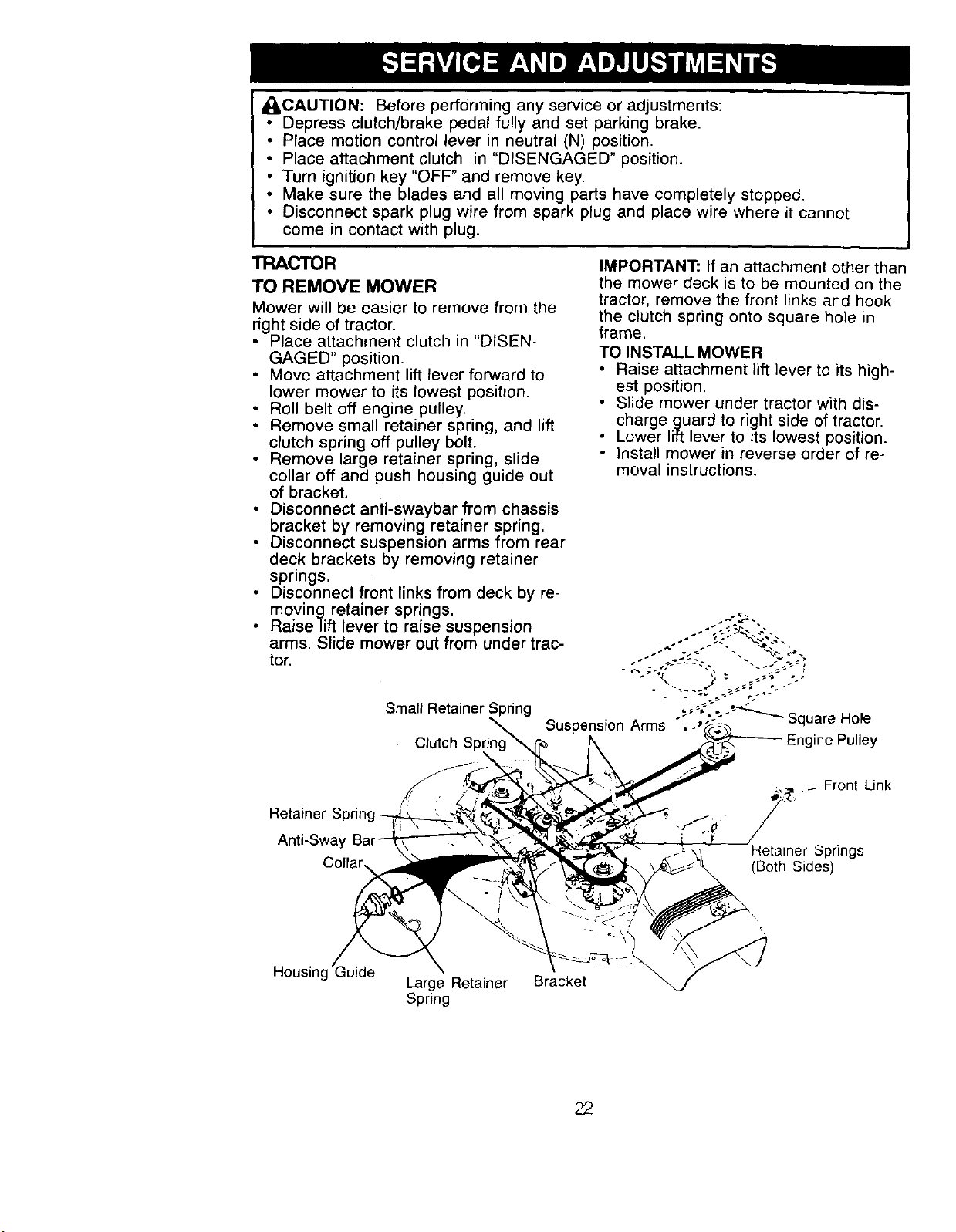
TRACTOR
TO REMOVE MOWER
Mower will be easier to remove from the
right side of tractor.
• Place attachment clutch in "DISEN-
GAGED" position.
• Move attachment lift lever forward to
lower mower to its lowest position.
• Roll belt off engine pulley.
• Remove small retainer spring, and lift
clutch spring off pulley bolt.
• Remove large retainer spring, slide
collar off and push housing guide out
of bracket.
• Disconnect anti-swaybar from chassis
bracket by removing retainer spring.
• Disconnect suspension arms from rear
deck brackets by removing retainer
springs.
Disconnect front links from deck by re-
moving retainer springs.
• Raise/ift lever to raise suspension
arms. Slide mower out from under trac-
tor.
Small Retainer Spring
Clutch
IMPORTANT: If an attachment other than
the mower deck is to be mounted on the
tractor, remove the front links and hook
the clutch spring onto square hole in
frame.
TO INSTALL MOWER
• Raise attachment lift ]ever to its high-
est position.
• Slide mower under tractor with dis-
charge guard to right side of tractor.
• Lower lift lever to its lowest position.
• Install mower in reverse order of re-
moval instructions.
Retainer S
Anti-Sway
_Front Link
_tainer Springs
(Both Sides)
Housing
Large Retainer Bracket
Spring
22
TO LEVEL MOWER HOUSING
Adjust the mower while tractor is parked
on level ground or driveway. Make sure
tires are properly inflated (See "PROD-
UCT SPECIFICATIONS" section of this
manual). If tires are over or
underinflated, you will not properly
adjust your mower.
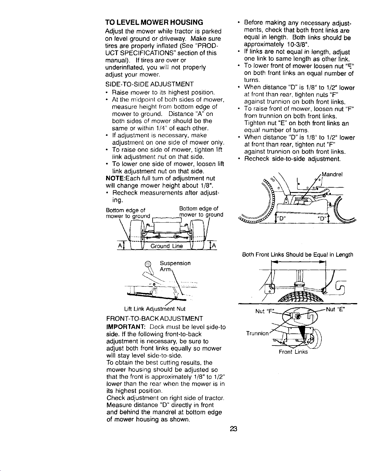
SIDE-TO-SIDE ADJUSTMENT
• Raise mower to its highest position.
• At the midpoint of both sides of mower,
measure height from bottom edge of
mower to ground. Distance "A" on
both sides of mower should be the
same or within 1/4" of each other.
• If adjustment is necessary, make
adjustment on one side of mower only.
• To raise one side of mower, tighten rift
link adjustment nut on that side.
• To lower one side of mower, loosen lift
link adjustment nut on that side.
NOTE:Each full turn of adjustment nut
will change mower height about 1/8".
• Recheck measurements after adjust-
ing.
Bottom edge of Bottom edge of
m°we_- groA_._...._, Ground Line _..._/T .._ nd
_r Suspension
m,
Lift Link Adjustment Nut
FRONT-TO-BACK ADJUSTMENT
IMPORTANT: Deck must be level side-to
side. If the following front-to-back
adjustment is necessary, be sure to
adjust both front links equally so mower
will stay level side-to-side.
To obtain the best cutting results, the
mower housing should be adjusted so
that the front is approximately 1/8" to 1/2"
lower than the rear when the mower is in
its highest position.
Check adjustment on right side of tractor.
Measure distance "D" directly in front
and behind the mandrel at bottom edge
of mower housing as shown.
23
• Before making any necessary adjust-
ments, check that both front links are
equal in length. Both links should be
approximately 10-3/8".
• If links are not equal in length, adjust
one link to same length as other link.
• To lower front of mower loosen nut "=."
on both front links an equal number of
turns.
• When distance "D" is 1/8" to 1/2" lower
at front than rear, tighten nuts "F"
against trunnion on both front links.
• To raise front of mower, loosen nut "F"
from trunnion on both front links.
Tighten nut "E" on both front links an
equal number of turns.
• When distance "D" is 1/8" to 1/2" lower
at front than rear, tighten nut "F"
against trunnion on both front links.
• Recheck side-to-side adjustment.
.Mandrel
Both Front Links Should be Equal in Length
Nut
Front Links
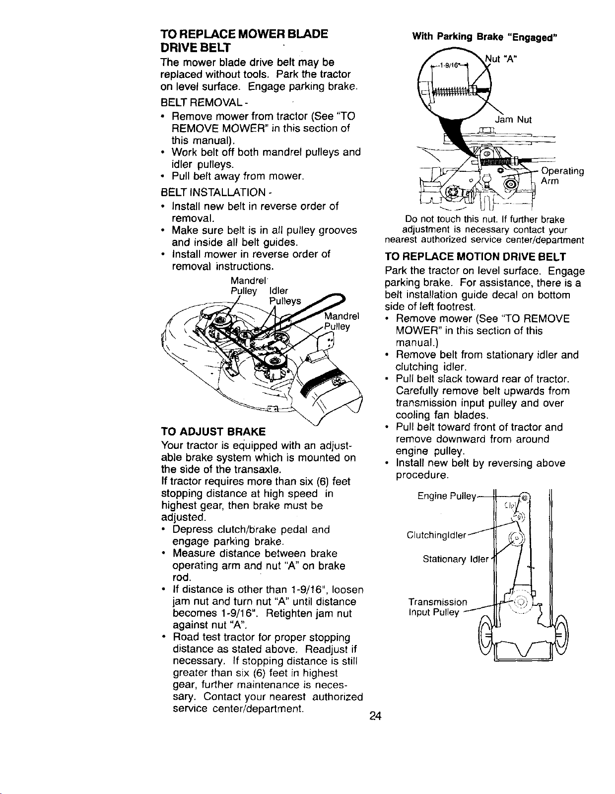
TO REPLACE MOWER BLADE
DRIVE BELT
The mower blade drive belt may be
replaced without tools, Park the tractor
on level surface. Engage parking brake.
BELT REMOVAL -
• Remove mower from tractor (See "TO
REMOVE MOWER" in this section of
this manual).
• Work belt off both mandrel pulleys and
idler pulleys.
• Pull belt away from mower.
BELT INSTALLATION -
• Install new belt in reverse order of
removal.
• Make sure belt is in all pulley grooves
and inside all belt guides.
• Install mower in reverse order of
removal instructions.
Mandrel
Pulley Idler
Pull
riley
TO ADJUST BRAKE
Your tractor is equipped with an adjust-
able brake system which is mounted on
the side of the transaxle.
If tractor requires more than six (6) feet
stopping distance at high speed in
highest gear, then brake must be
adjusted.
• Depress clutch/brake pedal and
engage parking brake.
• Measure distance between brake
operating arm and nut "A" on brake
rod.
• If distance is other than 1-9/16", loosen
jam nut and turn nut "A" until distance
becomes 1-9/16". Retighten jam nut
against nut "A",
• Road test tractor for proper stopping
distance as stated above. Readjust if
necessary. If stopping distance is still
greater than six (6) feet in highest
gear, further maintenance is neces-
sary. Contact your nearest authorized
service center/department.
With Parking Brake "Engaged"
Jam Nut
Arm
_J
Do not touch this nut. If further brake
adjustment is necessary contact your
nearest authorized service center/department
TO REPLACE MOTION DRIVE BELT
Park the tractor on level surface. Engage
parking brake. For assistance, there is a
belt installation guide decal on bottom
side of left footrest,
• Remove mower (See "TO REMOVE
MOWER" in this section of this
manual.)
• Remove belt from stationary idler and
clutching idler.
• Pull belt slack toward rear of tractor.
Carefully remove belt upwards from
transmission input pulley and over
cooling fan blades.
• Pull belt toward front of tractor and
remove downward from around
engine pulley.
• Install new belt by reversing above
procedure.
Engine Pulley--
Clutchingldler /
Stationary Idler'
Transmission
Input Pulley _
cJ-2
. _'oI I I
0
24
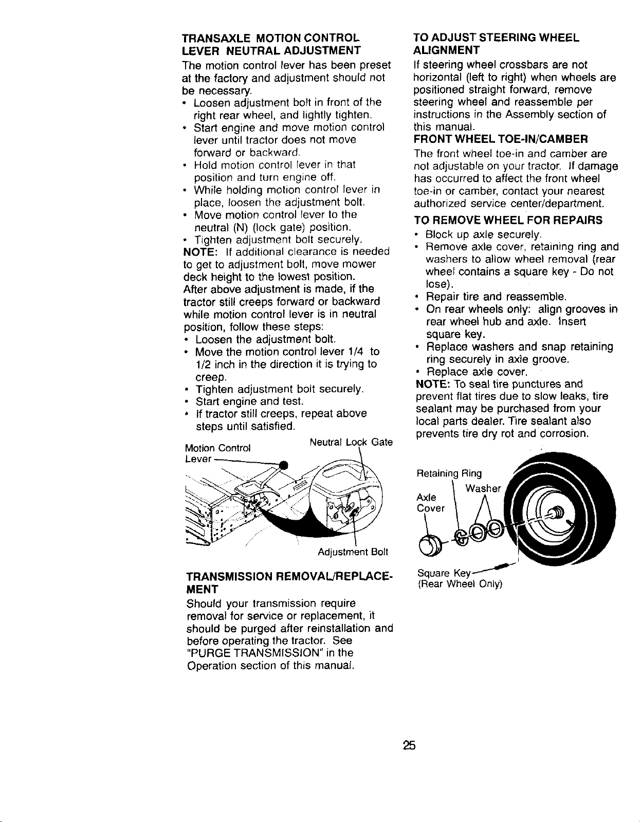
TRANSAXLE MOTION CONTROL
LEVER NEUTRAL ADJUSTMENT
The motion control lever has been preset
at the factory and adjustment should not
be necessary.
• Loosen adjustment bolt in front of the
right rear wheel, and lightly tighten.
• Start engine and move motion control
lever until tractor does not move
forward or backward.
• Hold motion control lever in that
position and turn engine off.
• While holding motion control lever in
place, loosen the adjustment bolt.
• Move motion control lever to the
neutral (N) (lock gate) position.
• Tighten adjustment bolt securely.
NOTE: If additional clearance is needed
to get to adjustment bolt, move mower
deck height to the lowest position.
After above adjustment is made, if the
tractor still creeps forward or backward
while motion control lever is in neutral
position, follow these steps:
• Loosen the adjustment bolt.
• Move the motion control lever 1/4 to
1/2 inch in the direction it is trying to
creep.
• Tighten adjustment bolt securely.
• Start engine and test.
• If tractor still creeps, repeat above
steps until satisfied.
Neutral Lock Gate
Motion Control
Adjustment Bolt
TRANSMISSION REMOVAL/REPLACE-
MENT
Should your transmission require
removal for service or replacement, it
should be purged after reinstallation and
before operating the tractor. See
"PURGE TRANSMISSION" in the
Operation section of this manual.
TO ADJUST STEERING WHEEL
ALIGNMENT
If steering wheel crossbars are not
horizontal (left to right) when wheels are
positioned straight forward, remove
steering wheel and reassemble per
instructions in the Assembly section of
this manual.
FRONT WHEEL TOE-IN/CAMBER
The front wheel toe-in and camber are
net adjustable on your tractor. If damage
has occurred to affect the front wheel
toe-in or camber, contact your nearest
authorized service center/department.
TO REMOVE WHEEL FOR REPAIRS
• Block up axle securely.
• Remove axle cover, retaining ring and
washers to allow wheel removal (rear
wheel contains a square key - Do not
lose).
• Repair tire and reassemble.
• On rear wheels only: align grooves in
rear wheel hub and axte. Insert
square key.
• Replace washers and snap retaining
ring securely in axle groove.
• Replace axle cover.
NOTE: To seal tire punctures and
prevent flat tires due to slow leaks, tire
sealant may be purchased from your
local parts dealer. Tire sealant also
prevents tire dry rot and corrosion.
Retaining Ring
Washer
Axle
Cover
I
Square Key ,_''_
(Rear Wheel Only)
25
TO START ENGINE WITH AWEAK
BATTERY
CAUTION: Lead-acid batteries
generate explosive gases. Keep sparks,
flame and smoking materials away from
batteries, Always wear eye protection
when around batteries,
If your battery is too weak to start the
engine, it should be recharged. (See
"BAI-FERY" in the MAINTENANCE
section of this manual).
If "jumper cables" are used for emer-
gency starting, follow this procedure:
IMPORTANT: Your tractor is equipped
with a 12 volt negative grounded system.
The other vehicle must also be a 12 volt
negative grounded system. Do not use
your tractor battery to start other vehicles.
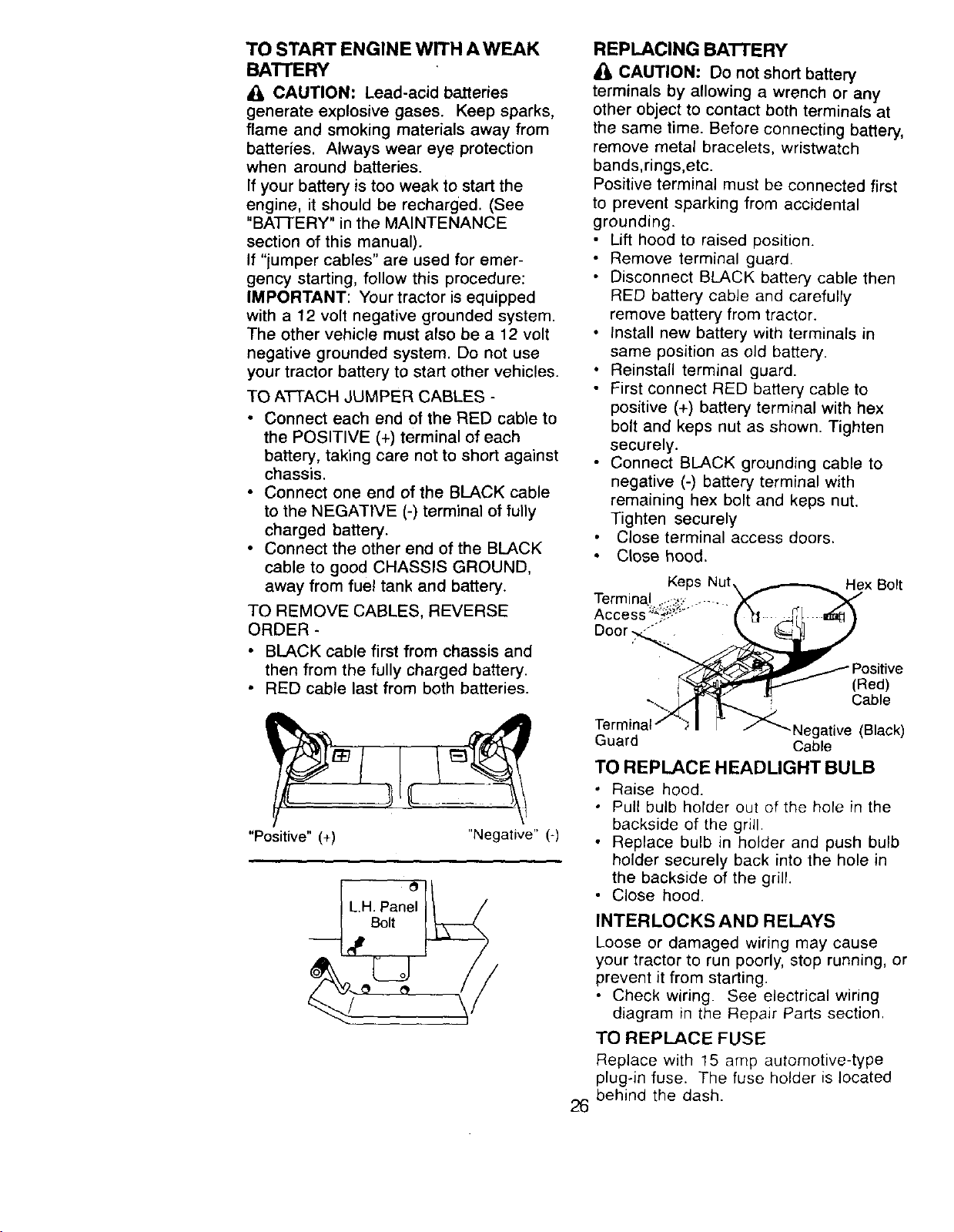
TO A'FI-ACH JUMPER CABLES -
• Connect each end of the RED cable to
the POSITIVE (+) terminal of each
battery, taking care not to short against
chassis.
• Connect one end of the BLACK cable
to the NEGATIVE (-) terminal of fully
charged battery.
• Connect the other end of the BLACK
cable to good CHASSIS GROUND,
away from fuel tank and battery.
TO REMOVE CABLES, REVERSE
ORDER -
BLACK cable first from chassis and
then from the fully charged battery.
RED cable last from both batteries.
"Positive" (+) "Negative" (-)
Bolt
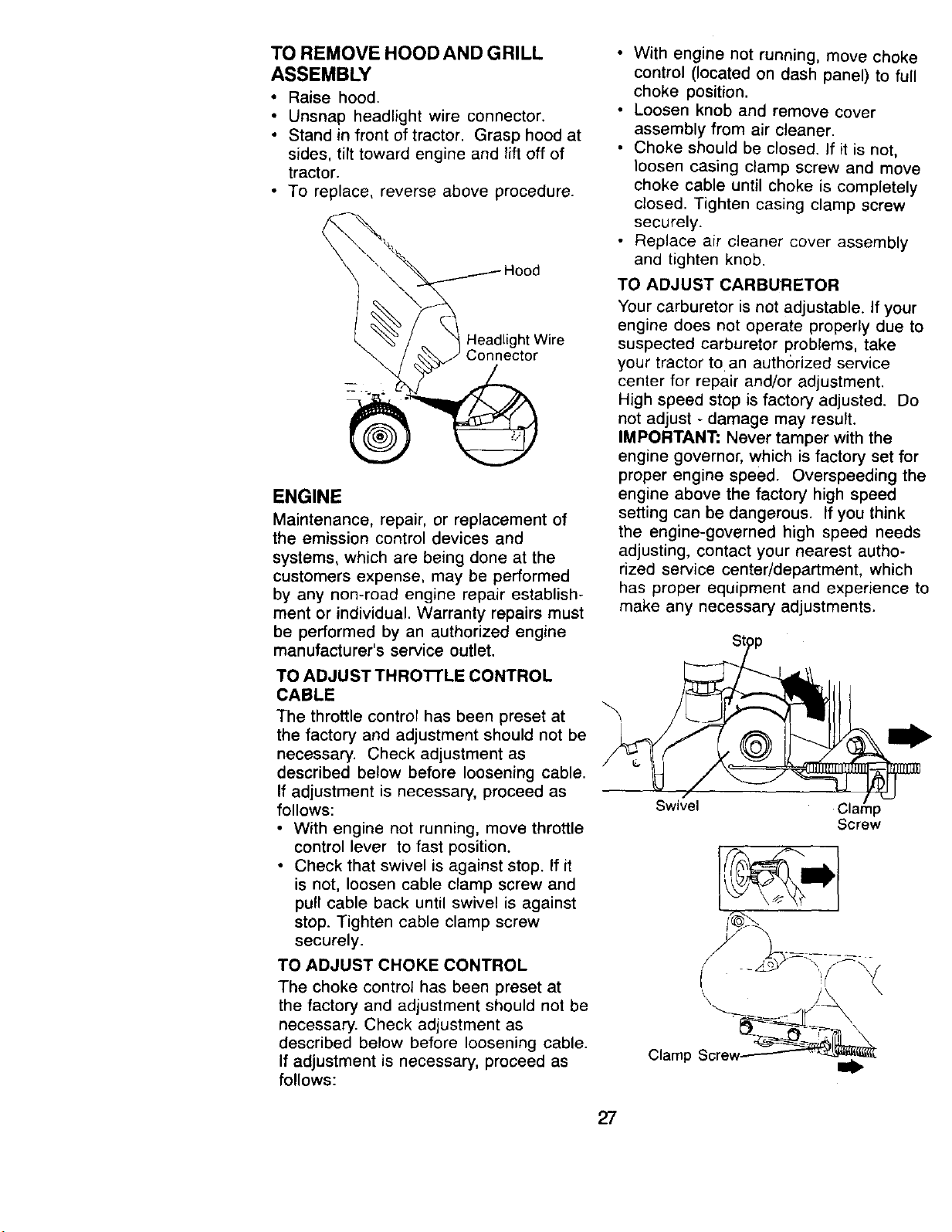
REPLACING BATTERY
CAUTION: Do not short battery
terminals by allowing a wrench or any
other object to contact both terminals at
the same time. Before connecting battery,
remove metal bracelets, wristwatch
bands,rings,etc.
Positive terminal must be connected first
to prevent sparking from accidental
grounding.
• Lift hood to raised position.
• Remove terminal guard.
• Disconnect BLACK battery cable then
RED battery cable and carefully
remove battery from tractor.
• Install new battery with terminals in
same position as old battery.
• Reinstall terminal guard.
• First connect RED battery cable to
positive (+) battery terminal with hex
bolt and keps nut as shown. Tighten
securely.
• Connect BLACK grounding cable to
negative (-) battery terminal with
remaining hex bolt and keps nut.
Tighten securely
Close terminal access doors.
Close hood.
Hex Bolt
26
(Red)
Cable
.Negative (Black)
Guard Cable
TO REPLACE HEADLIGHT BULB
• Raise hood.
• Pull bulb holder out of the hole in the
backside of the grill.
• Replace bulb in holder and push bulb
holder securely back into the hole in
the backside of the grill.
• Close hood.
INTERLOCKS AND RELAYS
Loose or damaged wiring may cause
your tractor to run poorly, stop running, or
prevent it from starting.
• Check wiring. See electrical wiring
diagram in the Repair Parts section.
TO REPLACE FUSE
Replace with 15 amp automotive-type
plug-in fuse. The fuse holder is located
behind the dash.
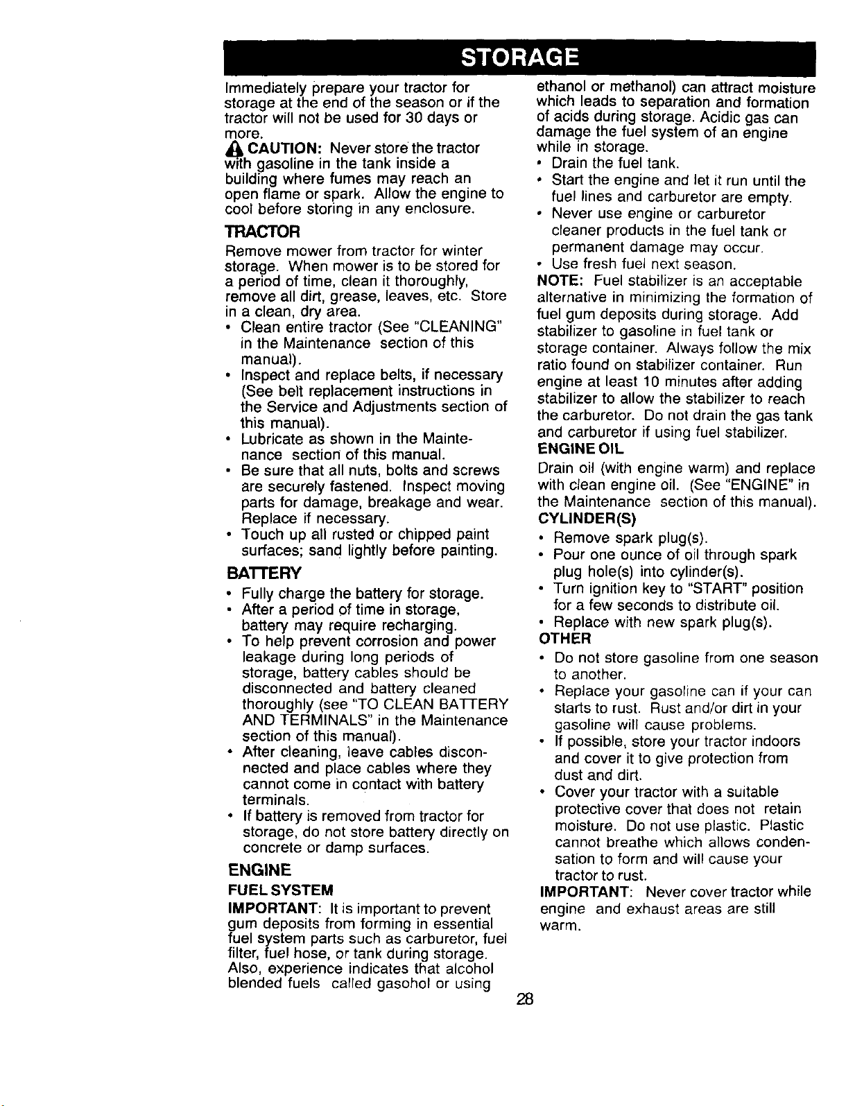
TO REMOVE HOOD AND GRILL
ASSEMBLY
• Raise hood.
• Unsnap headlight wire connector.
• Stand in front of tractor. Grasp hood at
sides, tilt toward engine and lift off of
tractor.
• To replace, reverse above procedure.
l Headlight Wire
ENGINE
Maintenance, repair, or replacement of
the emission control devices and
systems, which are being done at the
customers expense, may be performed
by any non-road engine repair establish-
ment or individual. Warranty repairs must
be performed by an authorized engine
manufacturer's service outlet.
TO ADJUST THRO'R'LE CONTROL
CABLE
The throttle control has been preset at
the factory and adjustment should not be
necessary. Check adjustment as
described below before loosening cable.
If adjustment is necessary, proceed as
follows:
• With engine not running, move throttle
control lever to fast position.
• Check that swivel is against stop. If it
is not, loosen cable clamp screw and
pull cable back until swivel is against
stop. Tighten cable clamp screw
securely.
TO ADJUST CHOKE CONTROL
The choke control has been preset at
the factory and adjustment should not be
necessary. Check adjustment as
described below before loosening cable.
If adjustment is necessary, proceed as
follows:
• With engine not running, move choke
control (located on dash panel) to full
choke position.
• Loosen knob and remove cover
assembly from air cleaner.
• Choke should be closed. If it is not,
loosen casing clamp screw and move
choke cable until choke is completely
closed. Tighten casing clamp screw
securely.
• Replace air cleaner cover assembly
and tighten knob.
TO ADJUST CARBURETOR
Your carburetor is not adjustable. If your
engine does not operate properly due to
suspected carburetor problems, take
your tractor to an authorized service
center for repair and/or adjustment.
High speed stop is factory adjusted. Do
not adjust - damage may result.
IMPORTANT: Never tamper with the
engine governor, which is factory set for
proper engine speed. Overspeeding the
engine above the factory high speed
setting can be dangerous. If you think
the engine-governed high speed needs
adjusting, contact your nearest autho-
rized service center/department, which
has proper equipment and experience to
make any necessary adjustments.
Swivel Clafnp
Screw
Clamp Screw_
27
Immediately prepare your tractor for
storage at the end of the season or if the
tractor will not be used for 30 days or
more.
_. CAUTION: Never store the tractor
wfth gasoline in the tank inside a
building where fumes may reach an
open flame or spark. Allow the engine to
cool before storing in any enclosure.
TRACTOR
Remove mower from tractor for winter
storage. When mower is to be stored for
a period of time, clean it thoroughly,
remove all dirt, grease, leaves, etc. Store
in a clean, dry area.
• Clean entire tractor (See "CLEANING"
in the Maintenance section of this
manual).
• Inspect and replace belts, if necessary
(See belt replacement instructions in
the Service and Adjustments section of
this manual).
• Lubricate as shown in the Mainte-
nance section of this manual.
• Be sure that all nuts, bolts and screws
are securely fastened. Inspect moving
parts for damage, breakage and wear.
Replace if necessary.
• Touch up all rusted or chipped paint
surfaces; sand lightly before painting.
BA'n'ERY
• Fully charge the battery for storage.
• After a period of time in storage,
battery may require recharging.
• To help prevent corrosion and power
leakage during long periods of
storage, battery cables should be
disconnected and battery cleaned
thoroughly (see "TO CLEAN BATI-ERY
AND TERMINALS" in the Maintenance
section of this manual).
• After cleaning, leave cables discon-
nected and place cables where they
cannot come in contact with battery
terminals.
• If battery is removed from tractor for
storage, do not store battery directly on
concrete or damp surfaces.
ENGINE
FUEL SYSTEM
IMPORTANT: It is important to prevent
gum deposits from forming in essential
fuel system parts such as carburetor, fuel
filter, fuel hose, or tank during storage.
Also, experience indicates that alcohol
blended fuels carled gasohol or using
ethanol or methanol) can attract moisture
which leads to separation and formation
of acids during storage. Acidic gas can
damage the fuel system of an engine
while in storage.
• Drain the fuel tank.
• Start the engine and let it run until the
fuel lines and carburetor are empty.
• Never use engine or carburetor
cleaner products in the fuel tank or
permanent damage may occur.
• Use fresh fuel next season.
NOTE: Fuel stabilizer is an acceptable
alternative in minimizing the formation of
fuel gum deposits during storage. Add
stabilizer to gasoline in fuel tank or
storage container. Always follow the mix
ratio found on stabilizer container. Run
engine at least 10 minutes after adding
stabilizer to allow the stabilizer to reach
the carburetor. Do not drain the gas tank
and carburetor if using fuel stabilizer.
ENGINE OIL
Drain oi! (with engine warm) and replace
with clean engine oil. (See "ENGINE" in
the Maintenance section of this manual).
CYLINDER(S)
• Remove spark plug(s).
• Pour one ounce of oil through spark
plug hole(s) into cylinder(s).
• Turn ignition key to "START" position
for a few seconds to distribute oiL
• Replace with new spark plug(s).
OTHER
• Do not store gasoline from one season
to another.
• Replace your gasoline can if your can
starts to rust. Rust and/or dirt in your
gasoline will cause problems.
• If possible, store your tractor indoors
and cover it to give protection from
dust and dirt.
• Cover your tractor with a suitable
protective cover that does not retain
moisture. Do not use plastic. Plastic
cannot breathe which allows conden-
sation to form and will cause your
tractor to rust.
IMPORTANT: Never cover tractor while
engine and exhaust areas are still
warm.
28
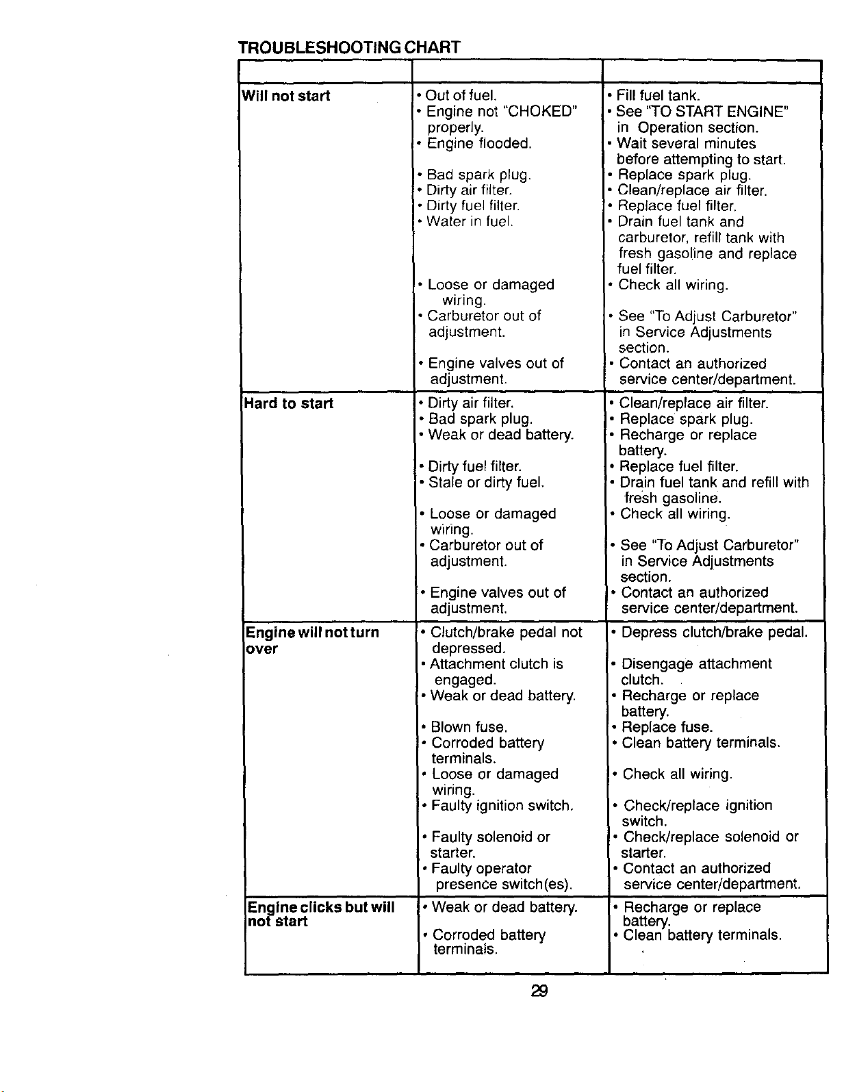
TROUBLESHOOTING CHART
Wili not start
Hard to start
Engine will not turn
over
Engine clicks but will
not start
• Out of fuel.
• Engine not "CHOKED"
properly.
• Engine flooded.
• Bad spark plug.
• Dirty air filter.
Dirty fuel filter.
Water in fuel.
I• Loose or damaged
wiring.
Carburetor out of
adjustment.
• Engine valves out of
adjustment.
• Dirty air filter.
• Bad spark plug.
• Weak or dead battery.
• Dirty fuel filter.
• Stale or dirty fuel.
• Loose or damaged
wiring.
• Carburetor out of
adjustment.
• Engine valves out of
adjustment.
• Clutch/brake pedal not
depressed.
• Attachment clutch is
engaged.
• Weak or dead battery.
• Blown fuse.
!. Corroded battery
terminals.
Loose or damaged
wiring.
• Faulty ignition switch,
• Faulty solenoid or
starter.
• Faulty operator
presence switch(es).
• Weak or dead battery.
• Corroded battery
terminals.
• Fill fuel tank.
See "TO START ENGINE"
in Operation section.
Wait several minutes
before attempting to start.
• Replace spark plug.
• Clean/replace air filter.
• Replace fuel filter.
• Drain fuel tank and
carburetor, refill tank with
fresh gasoline and replace
fuel filter.
• Check all wiring.
• See "To Adjust Carburetor"
in Service Adjustments
section.
• Contact an authorized
service center/department.
• Clean/replace air filter.
• Replace spark plug.
• Recharge or replace
battery.
• Replace fuel filter.
• Drain fuel tank and refill with
fresh gasoline.
• Check all wiring.
• See "To Adjust Carburetor"
in Service Adjustments
section.
I. Contact an authorized
service center/department.
• Depress clutch/brake pedal.
Disengage attachment
clutch.
• Recharge or replace
battery.
• Replace fuse.
• Clean battery terminals.
• Check all wiring.
• Check/replace ignition
switch.
• Check/replace solenoid or
starter.
• Contact an authorized
service center/department.
• Recharge or replace
battery.
• Clean battery terminals.
29
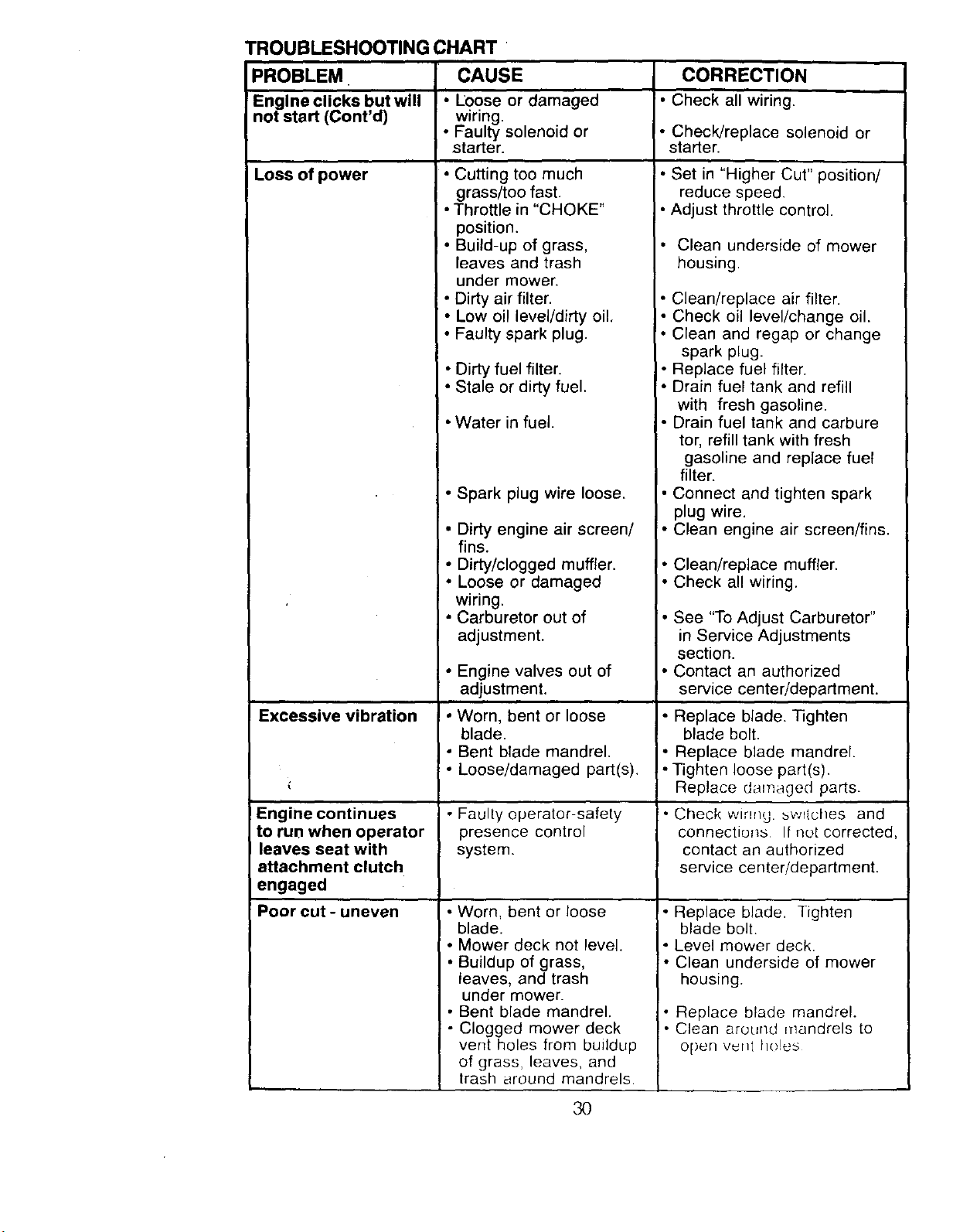
TROUBLESHOOTING CHART "
PROBLEM. CAUSE CORRECTION
Engine clicks but will I • Loose or damaged • Check all wiring.
not start (Cont'd) wiring.
• Faulty solenoid or • Check/replace solenoid or
starter, starter.
Loss of power
Excessive vibration
Engine continues
to run when operator
leaves seat with
attachment clutch
engaged
Poorcut-uneven
I, Cutting too much
grass/too fast.
• Throttle in "CHOKE"
position.
• Build-up of grass,
leaves and trash
under mower.
• Dirty air filter.
• Low oil level/dirty oil.
• Faulty spark plug.
• Dirty fuel filter.
• Stale or dirty fuel.
• Water in fuel.
• Spark plug wire loose.
• Dirty engine air screen/
fins.
• Dirty/clogged muffler.
• Loose or damaged
wiring.
• Carburetor out of
adjustment.
• Engine valves out of
adjustment.
* Worn, bent or loose
blade.
• Bent blade mandrel.
• Loose/damaged part(s).
• Faulty operator-safety
presence control
system.
• Worn, bent or loose
blade.
• Mower deck not level.
• Buildup of grass,
leaves, and trash
under mower.
• Bent blade mandrel.
• Clogged mower deck
vent holes from buildup
of grass, leaves, and
trash around mandrels
• Set in "Higher Cut" position/
reduce speed.
• Adjust throttle control.
• Clean underside of mower
housing.
• Clean/replace air filter.
• Check oil level/change oil.
• Clean and regap or change
spark plug.
• Replace fuel filter.
• Drain fuel tank and refill
with fresh gasoline.
• Drain fuel tank and carbure
tor, refill tank with fresh
gasoline and replace fuel
filter.
• Connect and tighten spark
plug wire.
• Clean engine air screen/fins.
• Clean/replace muffler.
• Check all wiring.
• See "To Adjust Carburetor"
in Service Adjustments
section.
• Contact an authorized
service center/department.
• Replace blade. Tighten
blade bolt.
• Replace blade mandrel.
• Tighten loose part(s).
Replace damaged parts.
• Check wrong. _wriches and
connections If not corrected,
contact an authorized
service center/department.
• Replace blade. Tighten
blade bolt.
• Level mower deck.
• Clean underside of mower
housing.
• Replace blade mandrel.
• Clean around mandrels to
open v_Ht holes
3O

TROUBLESHOOTING CHART
=ROBLEM CAUSE CORRECTION
dower blades will not • Obstruction in clutch • Remove obstruction.
rotate mechanism.
• Worn/damaged mower • Replace mower drive belt.
drive belt.
• Frozen idler pulley. • Replace idler pulley.
• Frozen blade mandrel. • Replace blade mandrel.
3oor grass discharge • Engine speed too slow.
teadlight(s) not
vorking (if so
.=quipped)
3attery will not charge
_oss of Drive
Engine "backfires"
Nhen turning engine
'OFF" ,
• Travel speed too fast.
• Wet grass.
• Mower deck not level,
• Low/uneven tire air
pressure.
• Worn, bent or loose blade.
• Buildup of grass,
leaves and trash under
mower.
• Mower drive belt worn.
• Blades improperly
installed.
• Improper blades used.
• Clogged mower deck
vent holes from buildup
of grass, leaves, and
trash around mandrels.
• Switch is "OFF".
• Bulb(s) burned out.
• Faulty light switch.
• Loose or damaged
wiring.
• Blown fuse.
• Bad battery cell(s),
• Poor cable connections.
• Faulty regulator (if so
equipped).
• Faulty alternator.
• Freewheel control in
"disengaged" position,
• Motion drive belt worn,
damaged or broken.
• Air trapped in transmiss-
ion during shipment or
servicing.
• Engine throttle control
not set at "SLOW"
position for 30 seconds
before stopping engine.
• Place throttle control in
"FAST" position.
• Shift to slower speed.
Allow grass to dry before
mowing,
Level mower deck.
• Check tires for proper air
pressure.
• Replace/sharpen blade,
Tighten blade bolt.
• Clean underside of mower
housing.
• Replace mower drive belt.
• Reinstall blades sharp edge
down.
• Replace with blades listed
in this manual.
• Clean around mandrels to
open vent holes,
• Turn switch "ON".
• Replace bulb(s).
• Check/replace light switch.
• Check wiring and connec
tions.
• Replace fuse.
• Replace battery.
• Check/clean all connec
tions.
• Replace regulator.
• Replace alternator.
• Place freewheel control in
"engaged" position.
• Replace motion drive belt.
• Purge transmission.
• Move throttle control to
"SLOW" position and allow
to idle for 30 seconds before
stopping engine.
31

SERVICE NOTES
32
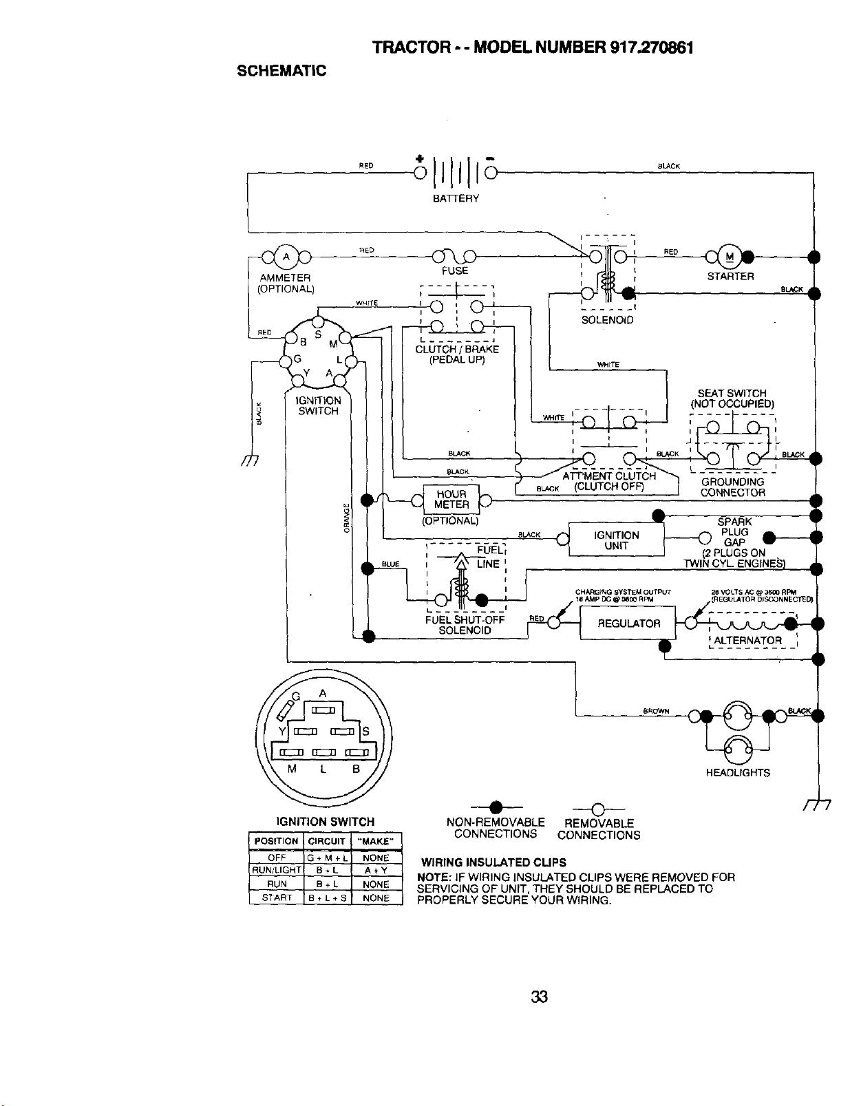
SCHEMATIC
TRACTOR - - MODEL NUMBER 917.270861
RED
BATTERY
8LACK
AMMETER FUSE !
(OPTIONAL) _-_ 1
' ', I I SOLENOID
L ....... J
WH{TE
)G L,
IGNITION
SWITCH
/;
(CLUTCH OFn
STARTER
BLACK
SEATSWiTCH
(NOT OCCUPIED)
GROUNDING
CONNECTOR
IGNITION SWITCH
POSITION CIRCUIT "MAKE"
NON-REMOVABLE REMOVABLE
CONNECTIONS CONNECTIONS
BROWN
HEADLIGHTS
OFF G+M+L
RUN/LIGHT B ÷ L
RUN B+L
START B + L + S
NONE WIRING INSULATED CLIPS
A÷Y
NOTE: IF WIRING INSULATED CLIPS WERE REMOVED FOR
NONE SERVICING OF UNIT, THEY SHOULD BE REPLACED TO
NONE PROPERLY SECURE YOUR WIRING.
33
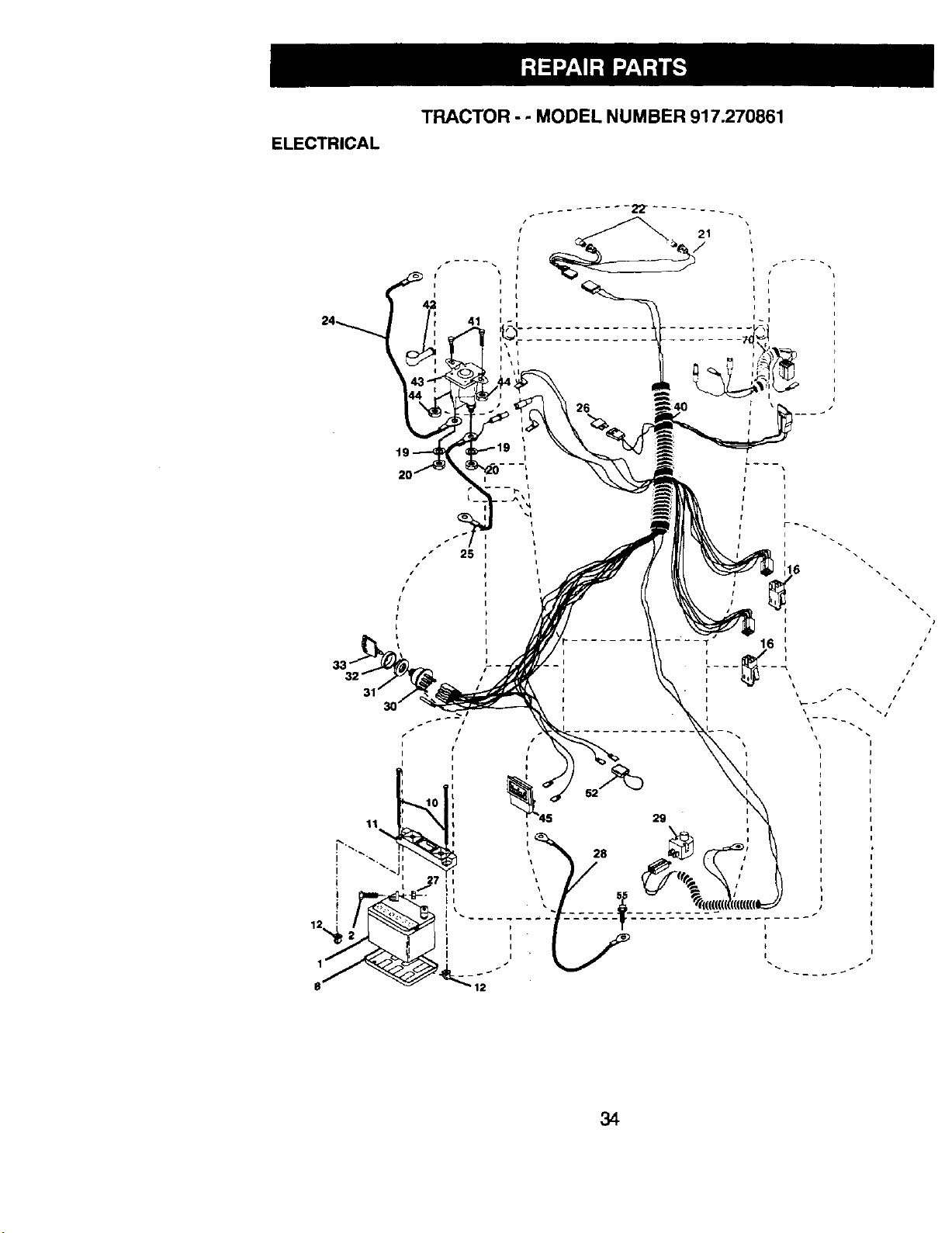
ELECTRICAL
TRACTOR - - MODEL NUMBER 917.270861
t
I
_~_
i I
i I
I
I i
24 41 i
/ 25
#/
I
I
I
I
I
I
11
I
I
I
t i
I i
I i
I
II
i #
I
I
_45 29
i- :: :::::::::....i....
#/
34
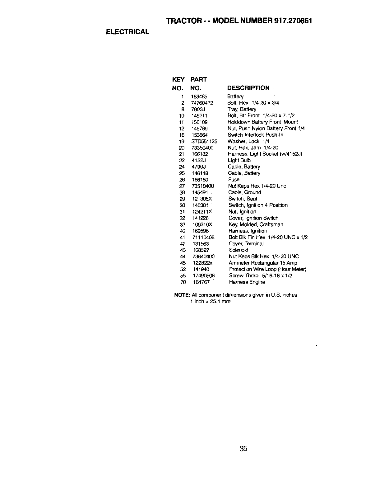
ELECTRICAL
TRACTOR - - MODEL NUMBER 917.270861
KEY PART
NO, NO. DESCRIPTION
1 163465 Battery
2 74760412 Bolt, Hex 1/4-20 x 3/4
8 7603J Tray, Battery
10 145211 Bolt, Btr Front 1/4-20 x 7-1/2
11 150109 Holddown Battery Front Mount
12 145769 Nut, Push Nylon Battery Front 1/4
16 153664 Switch Interlock Push-In
19 S'1"D551125 Washer, Lock 1/4
20 73350400 Nut, Hex, Jam 1/4-20
21 166182 Harness, Light Socket (w/4152J)
22 4152J Light Bulb
24 4799J Cable, Battery
25 146148 Cable, Battery
26 166180 Fuse
27 73510400 NutKeps Hex 1/4-20 Unc
28 145491 . Cable, Ground
29 121305X Switch, Seat
30 140301 Switch, Ignition 4 Position
31 124211X Nut, Ignition
32 141226 ' Cover, IgnitionSwitch
33 1C9310X Key, Molded, Craftsman
40 169596 Harness, ignition
41 71110408 Bolt BIk Fin Hex 1/4-20 UNC x 1/2
42 131563 Cover,Terminal
43 168327 Sok_noid
44 73640400 Nut Keps BIkHex 1/4-20 UNC
45 122822x Ammeter Rectangular15Amp
52 141940 Protection Wire Loop (Hour Meter)
55 17490508 Screw Thdrol 5/16-18 x 1/2
70 164767 " Harness Engine
NOTE: Allcomponent dimensionsgiven in U.S. inches
1 inch = 25.4 mm
35
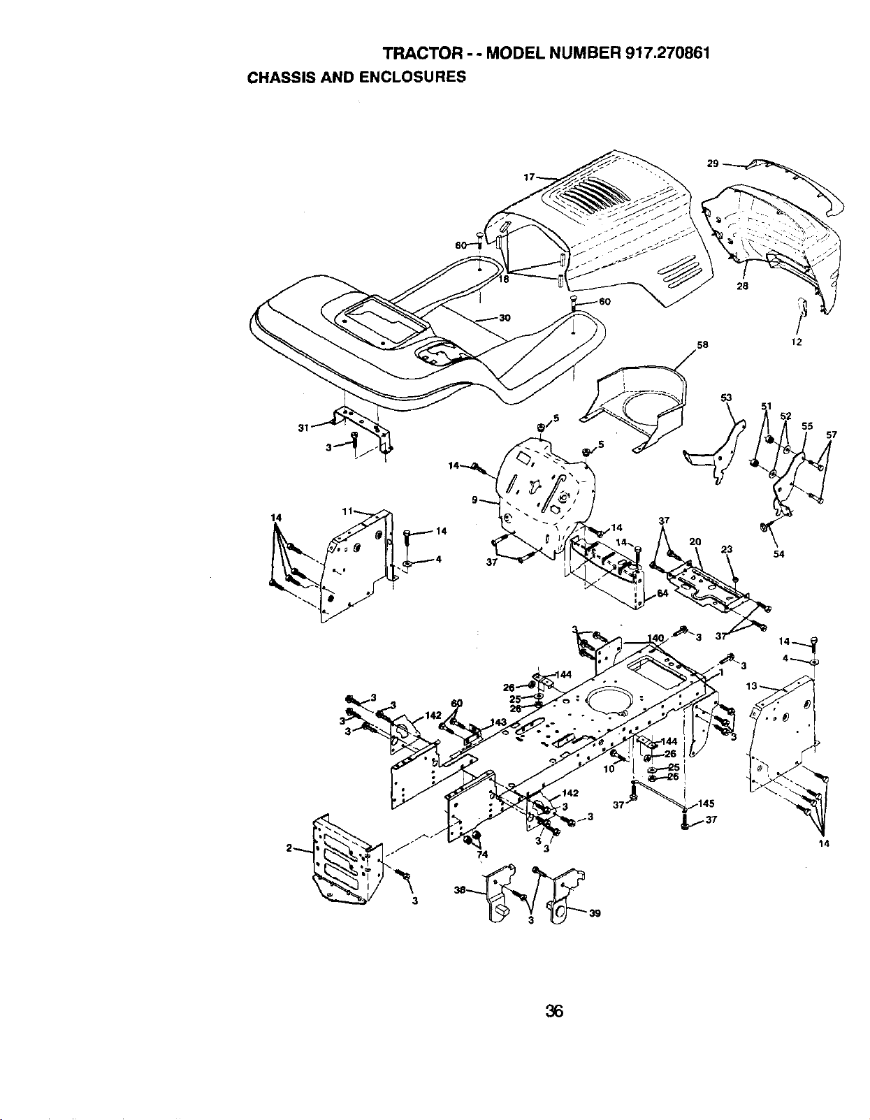
TRACTOR - - MODEL NUMBER 917.270861
CHASSIS AND ENCLOSURES
28
58 12
31
23 54
14
36
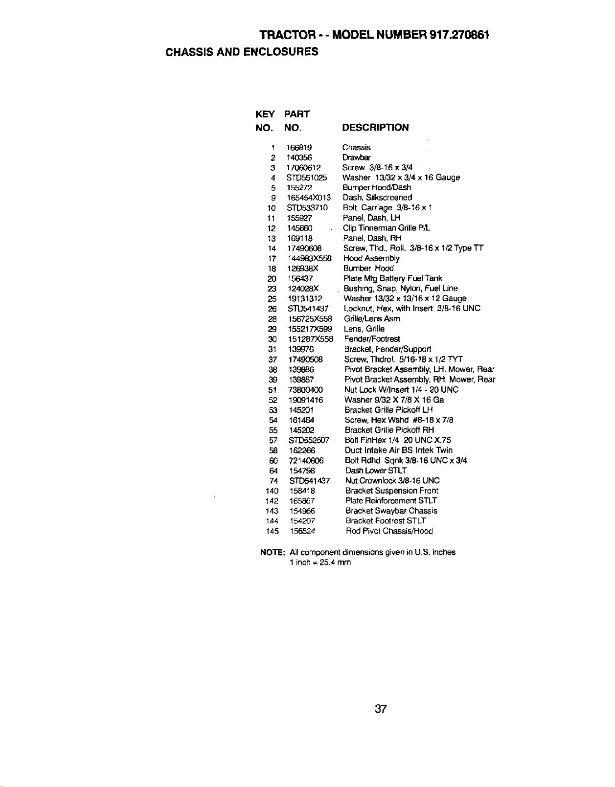
TRACTOR - - MODEL NUMBER 917.270861
CHASSIS AND ENCLOSURES
KEY PART
NO. NO. DESCRIPTION
1 166819
2 14O356
3 17060612
4 STD551025
5 155272
9 165454X013
10 STD533710
11 155927
12 145660
13 169118
14 17490608
17 144983X558
18 126&.38X
20 156437
23 124028X
25 19131312
26 STD541437
28 156725)(558
29 155217X599
30 151287)(558
31 139976
37 17490,508
38 139886
39 139887
51 73800400
52 19091416
53 145201
54 161464
55 145202
57 STD5,52,507
58 162266
60 72140606
64 154798
74 STD541437
140 158418
142 165867
143 154£66
144 154207
145 156524
NOTE:
Chassis
Drawbar
Screw 3/8-16 x 3/4
Washer 13/32 x 3/4 x 16 Gauge
Bumper Hcod/Dash
Dash, Silkscreened
Bolt, Carriage 3/8-16 x 1
Panel, Dash, LH
Clip"13nnermanGrille P/L
Panel, Dash, RH
Screw, Thd., Roll. 3/8-16 x 1/2Type TT
Hood Assembly
Bumber Hood
Plate Mtg Battery Fuel Tank
Bushing, Snap, Nylon, FuelUne
Washer t 3/32 x 13/16 x 12Gauge
Locknut, Hex, with Insert 3/8-16 UNC
Grille/Lens Asm
Lens, Grille
Fender/Footrest
Bracket, Fender/Support
Screw, Thdrol. 5/16-18 x 1/2TYT
Pivot Bracket Assembly, LH, Mower, Rear
Pivot BracketAssembly, RH, Mower, Rear
Nut Lock W/Insert 1/4 - 20 UNC
Washer 9/32 X 7/8 X 16 Ga.
Bracket Grille Pickoff LH
Screw, Hex Wshd #8-18 x 7/8
Bracket Grille Pickoff RH
Bolt FinHex 1/4 -20 UNC X.75
Duct Intake Air BS Intek Twin
Boit Rdhd Sqnk 3/8-16 UNC x 3/4
DashLowerSTLT
NutCrownlock 3/9-16 UNC
Bracket Suspension Front
Plate Reinforcement STLT
Bracket Swaybar Chassis
Bracket Footrest STLT
Rod Pivot Chassis/Hood
All component dimensionsgiven in U.S. inches
1inch = 25.4 mm
37
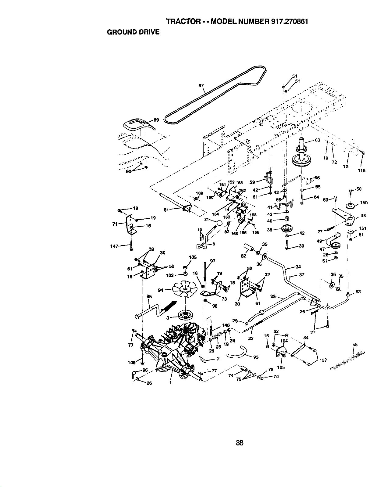
TRACTOR - - MODEL NUMBER 917.270861
GROUND DRIVE
116
77
26 1
26
22 104 _
27
84
38
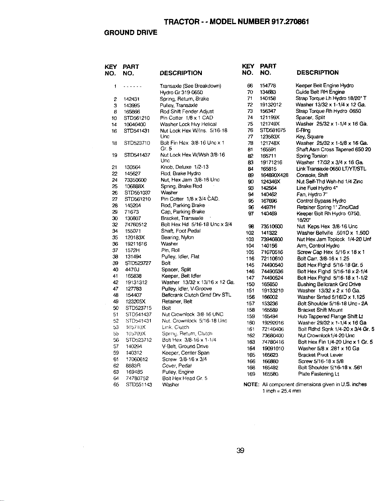
TRACTOR - - MODEL NUMBER 917.270861
GROUND DRIVE
KEY PART KEY PART
NO, NO. DESCRIPTION NO. NO. DESCRIPTION
t Transaxle (See Breakdown) 66 154778
Hydro Gr 319 0650 70 134_
2 142431 Spring, Return, Brake 71 140158
3 143995 Pulley, Transaxle 72 19132012
8 165866 Rod Shift Fender Adiust 73 156347
10 STD561210 Pin Cotter 1/8 x 1 CAD 74 121199X
14 10040400 Washer Lock Hvy Helical 75 121749)(
16 STD541431 Nut Lock Hex W/Ins. 5/16-18 76 _1075
Unc 77 123583X
18 STD523710 Bolt Fin Hex 3/8-16 Uric x 1 78 121748X
Gr. 5 81 165591
19 bmFD541437 Nut Lock Hex W/Wsh 3/8-16 82 165711
Unc 83 19171216
21 130564 Knob, De{uxe 1/2-13 84 165815
22 145627 Rod, Brake Hydro 89 164890)(428
24 73350600 Nut, Hex Jam 3/8-16 Unc 90 124346X
25 106888X Spring, Brake Rod 93 142564
26 STD.55103"7 Washer 94 1
27 STD561210 Pin Cotter 1/8 x 3/4 CAD. £5 167686
28 145204 Rod, Parking Brake £6 4497H
29 71673 Cap, Parking Brake 97 14044_
30 130807 Bracket, Transaxle
32 74760512 Bolt Hex Hd 5/16-18 Unc x 3/4 96 73510600
34 155071 Shaft, Foot Pedal 102 141322
35 120183X Bearing, Nylon 103 7_
36 19211616 Washer 104 140156
37 1572H Pin, Roll 105 71070516
38 131494 Pulley, Idler, Plat 116 72110610
39 STD523727 Bolt 145 74490540
40 4470J Spacer, Spilt 146 744.90536
41 165838 Keeper, Belt Idler 147 744.90524
42 19131312 Washer 13/32 x 13/16x 12 Ga. 150 165850
47 127783 Pulley, Idler, V-Groove 151 19133210
48 154407 Belldrank Clutch Grnd Dry STL 156 166002
49 123205X Retainer, Belt 157 153236
50 STD523715 Bolt 158 165589
51 STD541437 Nut Crownldck 3/8 16UNC 159 165494
52 STOb41431 Nut. Crownlock 5/16-18 Unc 160 19292016
53 1()57 I(JX Link Clutch 161 72140406
5b 106709X Sprrr]g. Return, Clutch 162 73680400
5_ STD523712 Belt Hex 3/8-16 x 1-1/4 163 74760416
57 140294 V-Be_, Ground Drive 164 19091010
59 140312 Keeper, Center Span 165 165623
61 17060612 Screw 3/8-16 x 3/4 166 166880
62 8883R Cover, Pedal 168 165492
63 169485 Pulley, Engine 169 165580
64 74780752 Bolt Hex Head Gr. 5
65 STL)551143 Washer
Keeper Belt Engine Hydro
Guide Belt RH Engine
Strap Torque Lh Hydro 18/20" T
Washer 13/32 x 1-1/4 x 12 Ga.
Strap Torque Rh Hydro 0650
Spacer, Split
Washer 25/32 x 1-1/4 x 16 Ga.
E-Ring
Key,Square
Washer 25/32 x t-5/8 x 16 Ga.
ShaftAsm Cross Tapered 650 20
SpdngTorsion
Washer 17/32 x 3/4 x 16 Ga.
LinkTransaxld 0650 LT/YT/STL
Console, Shift
Nut Self-Thd Wsh-hd 1/4Zinc
Line Fuel Hydro 4"
Fan, Hydro 7"
Control Bypass Hydro
Retainer Spring 1" Zinc/Cap
Keeper Bolt Rh Hydro 0750.
18/20'
Nut Keps Hex 3/8-16 Uric
Washer Bel[ville .501D x 1,50D
Nut Hex Jam Topldck 1/4,-20Unf
Arm, Control Hydro
Screw Cap Hex 5/16x 18x 1
Bolt Carr. 3/8-16 x 1.25
Bolt Hex Flghd 5/16-18 Gr. 6
Bolt Hex Flghd 5/16-16 x 2-1/4
Bolt Hex Flghd 5/16-18 x 1-1/2
Bushing Bellcrank Grd Drive
Washer 13/32 x 2 x 10 Ga.
Washer Srrted 5/161Dx 1.125
Bolt Shoulder 5/16-18 Uno - 2.A
Bracket Shift Mount
Hub Tappered Flange Shift Lt
Washer 29/32 x 1-1/4 x 16 Ga
Bolt Rdhd Sqnk 1/4-20 x 3/4 Gr. 5
NutCrownlockl/4-20 Unc
Bolt Hex Fin 1/4-20 Un¢x 1 Gr. 5
Washer 5/8 x .281 x 10 Ga
Bracket Pivot Lever
Screw 5/16-18 x 6/8
Bolt Shoulder 5/16-18 x .561
Plate Fastening Lt
NOTE: All component dimensions given in U.S. inches
1 inch = 26.4 mm
39
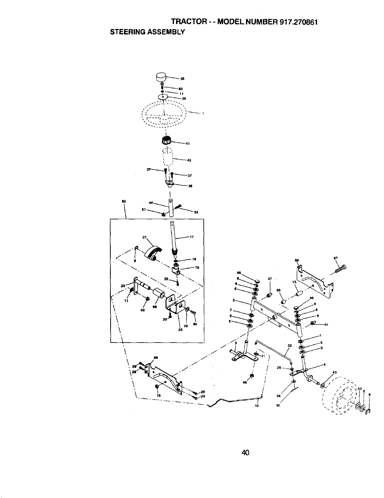
TRACTOR - - MODEL NUMBER 917.270861
STEERING ASSEMBLY
g
i
i
117
'\ _
\
40
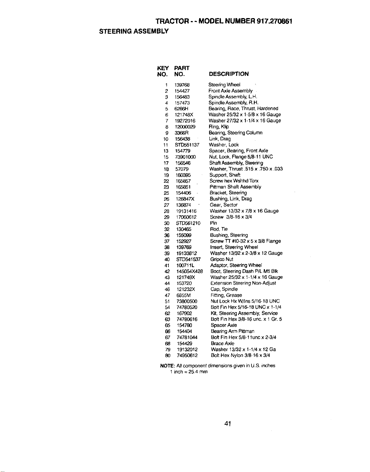
TRACTOR - - MODEL NUMBER 917.270861
STEERING ASSEMBLY
KEY PART
NO. NO. DESCRIPTION
1 139768 SteedngWheel
2 154427 Front Axle Assembly
3 156483 SpindleAssembly, LH.
4 157473 Spindle Assembly, R.H.
5 6266H Bearing, Race, Thrust, Hardened
6 121748X Washer 25/32 x 1-5/8 x 16 Gauge
7 19272016 Washer 27/32 x 1-1/4 x 16Gauge
8 12000029 Ring, Klip
9 3366R Bearing,Steering Column
10 156438 Link, Drag
11 STD551137 Washer, Lock
13 154779 Spacer, Bearing, Front Axle
15 73901000 Nut, Lock, Flange 5/8-11 UNC
17 156546 Shaft Assembly,Steering
18 57079 Washer, Thrust .515 x ,750 x .D33
19 160G95 Support, Shaft
22 165857 Screw hex Wshhd Torx
23 165851 Pittman Shaft Assembly
25 154406 Bracket, Steering
26 126847X Bushing, Link, Drag
27 136874 Gear, Sector
28 19131416 Washer 13/32 x 7/8 x 16 Gauge
29 17060612 Screw 3/8-16x3/4
30 STD561210 Pin
32 130465 Rod,Tie
36 155099 Bushing, Steering
37 152927 Screw Tl" #10-32x 5x 3/8 Flange
38 139769 Insert, Steering Wheel
39 19133812 Washer 13/32 x 2-3/8 x 12 Gauge
40 STD541537 Gdpco Nut
41 100711L Adaptor, Steering Wheel
42 145054X428 Boot, Steering Dash P/L Mtl BIk
43 121749X Washer 25/32 x 1-1/4 x 16 Gauge
44 153720 Extension Steering Non-Adjust
46 121232)< Cap, Spindle
47 6855M Fitting, Grease
51 73800500 Nut LockHxW/Ins 5/16-18 UNC
54 74780520 Bolt FinHex 5/16-18 UNC x 1-1/4
62 167902 Kit, Steedng Assembly, Service
63 74780616 Bolt Fin Hex 3/8-16 uric. x 1 Gr. 5
65 154780 Spacer Axle
66 154404 Bearing Arm Piftman
67 74781044 BoltFin Hex 5/8-11unc x 2-3/4
68 154429 Brace Axle
79 19132012 Washer 13/32 x 1-1/4 x 12 Ga
80 74950612 Bolt Hex Nylon 3/8-16 x 3/4
NOTE: All component dimensions given in U.S, inches
1 inch = 25.4 mm
41
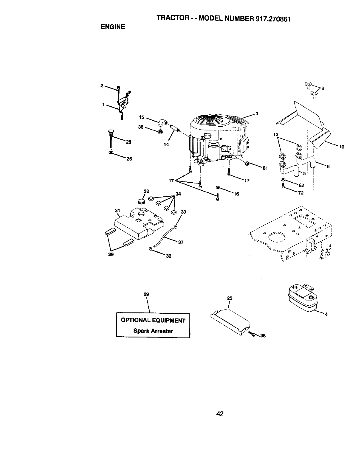
ENGINE
TRACTOR - - MODEL NUMBER 917.270861
2
1
31
39
14
32
13
29
OPTIONAL EQUIPMENT
Spark Arrester
23
/
42
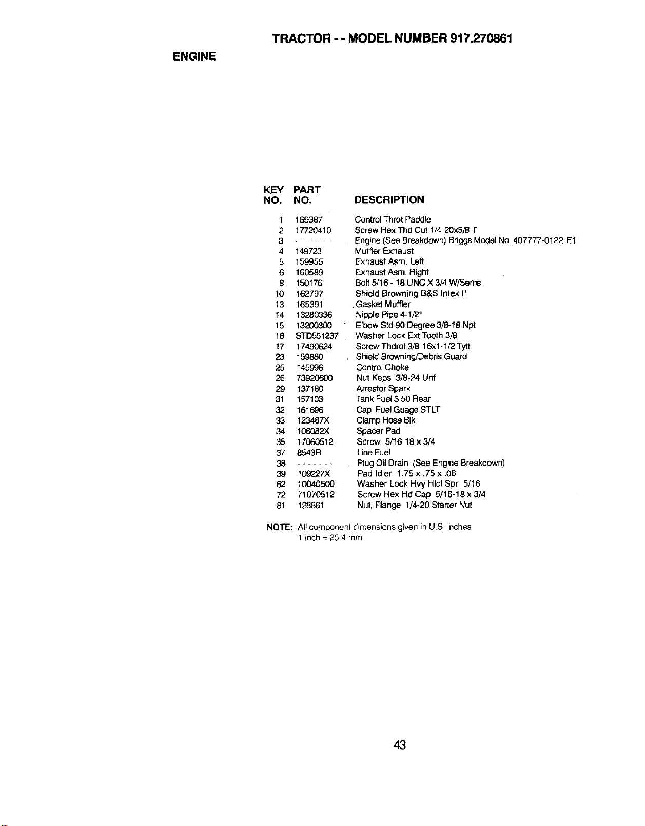
ENGINE
TRACTOR - - MODEL NUMBER 917.270861
KEY PART
NO. NO. DESCRIPTION
1 169387
2 17720410
3 ......
4 149723
5 159955
6 160589
8 150178
10 162797
13 165391
14 13280336
15 13200300
16 STD551237
17 174,90624
23 159880
25 145996
26 73920600
29 137180
31 157103
32 161686
33 123487X
34 106082X
35 1706O512
37 8543R
38 .......
39 109227X
62 10O4O5OO
72 71070512
81 128861
Control Throt Paddle
Screw Hex Thd Cut 1/4-20x5/8 T
Engine (See Breakdown) BriggsModel No. 407777-0122-E1
Muffler Exhaust
Exhaust Asm. Left
Exhaust Asm. Right
Bolt 5/16 - 18 UNC X 3/4 W/Seres
Shield Browning B&S Intek II
Gasket Muffler
Nipple Pipe 4-1/2"
ErbowStd gODegree 3/8-18 Npt
Washer Lock Ext Tooth 3/8
Screw Thdrol 3/8-16"x1-1/2Tytt
Shield Browning/DebrisGuard
ControlChoke
Nut Keps 3/8-24 Unf
Arrestor Spark
Tank Fuel3 50 Rear
Cap FuelGuage STLT
Clamp Hose BIk
Spacer Pad
Screw 5/16-18 x 3/4
Une Fuel
Plug Oil Drain (See Engine Breakdown)
Pad Idler 1.75 x ,75 x .06
Washer Lock Hvy HIcl Spr 5/16
Screw Hex Hd Cap 5/16-18 x 3/4
Nut, Flange 1/4-20 Starter Nut
NOTE: All component dimensions given in U.S. inches
1 inch = 254 mm
43
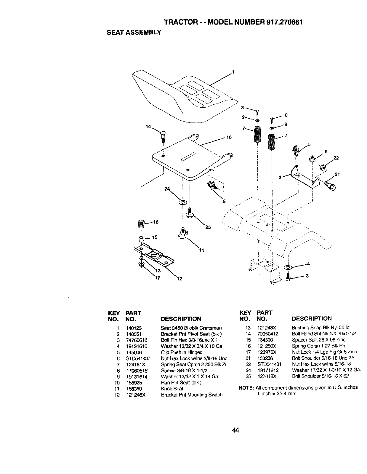
TRACTOR - - MODEL NUMBER 917.270861
SEAT ASSEMBLY
KEY PART KEY PART
NO. NO. DESCRIPTION NO. NO.
Seat 3450 BIk/'olkCraftsman 13 121248X
Bracket PntPivotSeat (blk) 14 72050412
BoltFinHex3/8-16une X 1 15 134,300
Washer 13/32 X 3/4 X 10 Ga 16 121250X
ClipPushtnHinged 17 123976)(
NOtHex Lock w/Ins 3/8-16 Uric 21 153236
Spdng Seat Cprsn 2250 BIkZi 22 STD541431
Screw 3/8-16 X 1-1/2 24 19171912
Washer 13/32 X 1X 14Ga 25 127918X
Pan Pnt Seat (blk)
Knob Seat
Bracket Pnt Mounting Switch
1 140123
2 140551
3 74760616
4 19131610
5 145006
6 _1437
7 124181X
8 17060616
9 19131614
10 155925
11 166369
12 121246X
DESCRIPTION
Bushing Snap Bfk Ny150 Id
Bolt Rdhd Sht Nk 1/4-20x1-1/2
Spacer Split 28 X 96 Zinc
Spring Cprsn 1 27 BIk Pnt
NOt Lock 1/4 Lge Fig Gr 5 Zinc
Bolt Shoulder 5/16-18 Unc-2A
Nut Hex Lock w/Ins 5/16-18
Washer 17/32 X 1-3/16 X 12 Ga.
Bolt Shoulder 5/16-18 X 62
NOTE: All component dimensions given in U.S, inches
1 inch = 25,4 mm
44
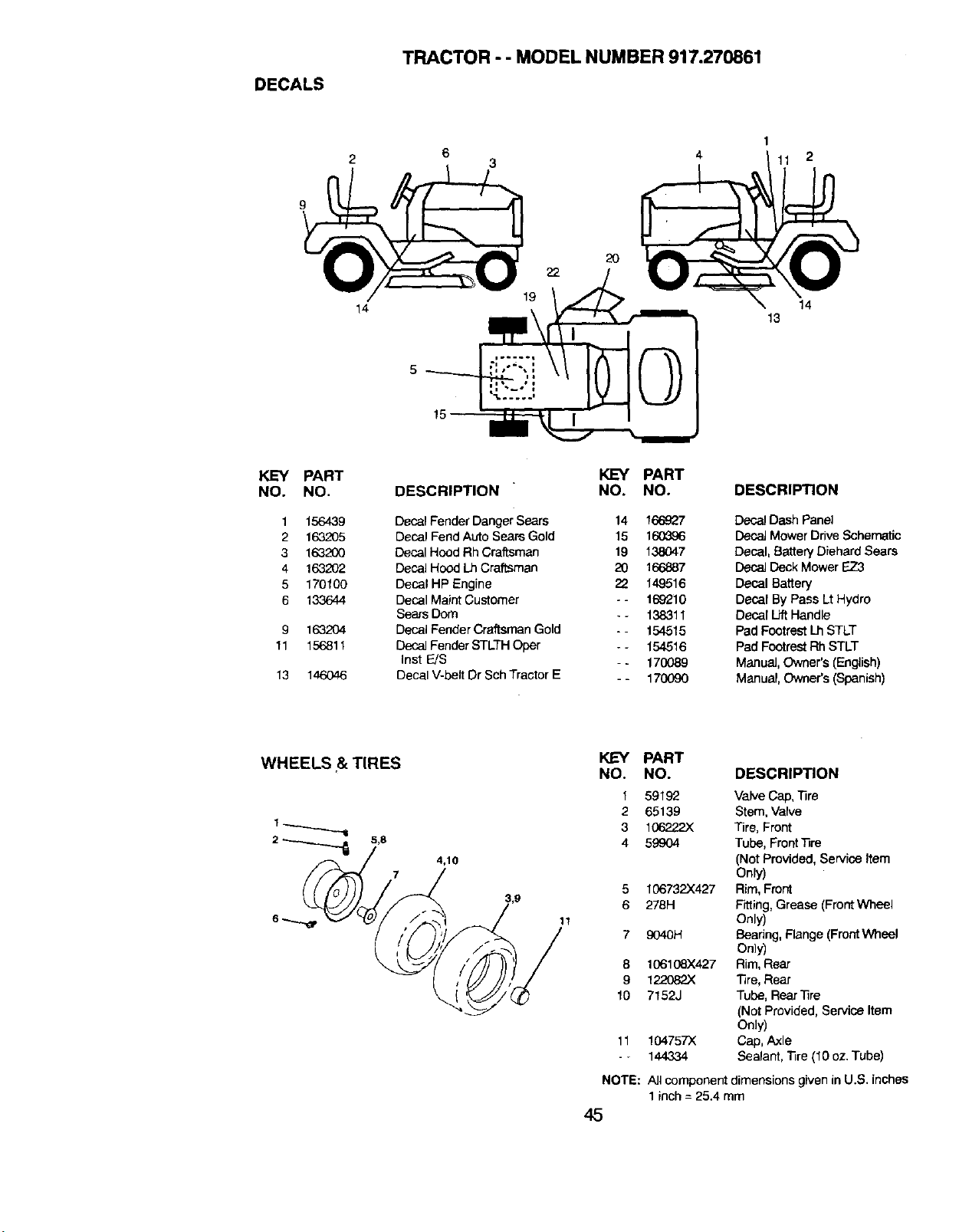
DECALS
TRACTOR - - MODEL NUMBER 917.270861
3
1
11 2
9
KEY PART
NO. NO.
1 156439
2 163205
3 163200
4 163202
5 170100
6 133644
9 163204
11 156811
13 146046
14
2O
19
KEY PART
DESCRIPTION NO. NO.
Decal FenderDangerSears 14 166_2t7
Decal Fend Auto Sears Gold 15 160_a6
Decal Hood Rh Craftsman 19 138047
DecalHood Lh Craftsman 20 166887
DecaIHP Engine 22 149516
Decal Maint Customer - - 169210
Sears Dom * - 138311
Decal Fender Craftsman Gold - - 154515
DecalFender STLTH Oper - - 154516
Inst E/S - - 170089
Decal V-belt Dr SchTractor E - - 170090
14
13
DESCRIPTION
DecalDash Panel
Decal Mower Drive Schematic
Decal, Battery Diehard Sears
Decal Deck Mower EZ3
Decal Battery
Decal By Pass Lt Hydro
Decal LiftHandle
Pad Footrest Lh STLT
Pad Footrest Rh STLT
Manual,Owner's (English)
Manual, Owner's (Spanish)
WHEELS r & TIRES
2 _ 5,8
4,10
KEY
NO.
1
2
3
4
5
6
11
7
8
9
lO
11
NOTE:
45
PART
NO. DESCRIPTION
59192 Valve Cap,lira
65139 Stem, Valve
106222X Tire, Front
59904 Tube, Front'nre
(Not Provided, Service Item
Only)
106732X427 Rim, Front
276H Fitting,Grease (FrontWheal
Only)
9040H E}eadng,Flange (FrontWheel
Only)
106108X427 Rim,Rear
122082X Tire, Rear
7152J Tube, Rear'l]re
(Not Provided, Service Item
Only)
104757X Cap, Axle
144334 Sealant, "iire (10oz, Tube)
All component dimensions given in U.S. inches
1 inch = 25.4 mm
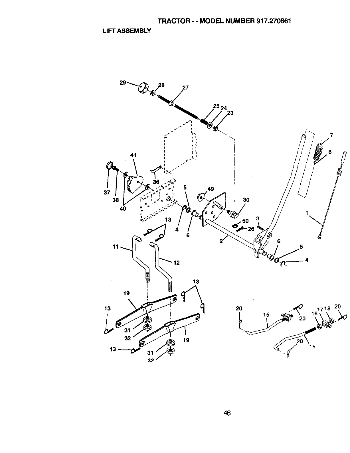
TRACTOR - - MODEL NUMBER 917.270861
LIFT ASSEMBLY
28 27
37
38
40
13
4
5
6
13
19
13
25 24
23
49
6
5
2O
7
8
2O
46
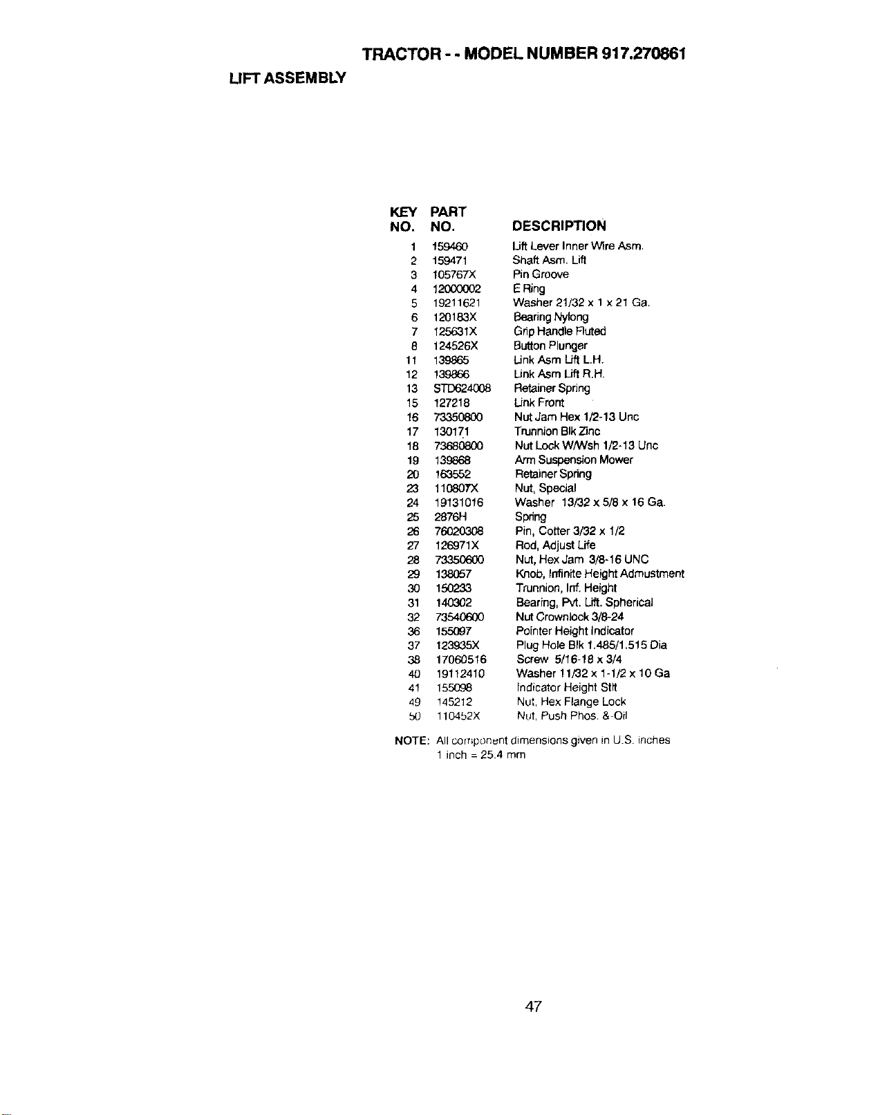
TRACTOR - - MODEL NUMBER 917.270861
LIFT ASSEMBLY
KEY PART
NO. NO. DESCRIPTION
1 159460 LiftLever Inner Wire Asm.
2 159471 Shaft Asm. Lift
3 105767)( PinGroove
4 12000002 E Ring
5 19211621 Washer 21/32 x 1 x21 Ga.
6 120183X BearingNylong
7 125631X Gnp Handle Fluted
8 124526X Button Plunger
11 139865 LinkAsm Lift LH.
12 139866 Link Asm Lift R.H.
13 S_4008 Retainer Spdng
15 127218 Unk Front
16 73350800 NutJam Hex 1/2-13 Unc
17 130171 Trunnion BIkZinc
18 73680800 Nut Lock WNVsh 1/2-13 Unc
19 139868 Arm Suspension Mower
20 163552 Retainer Spring
23 110807X Nut, Special
24 19131016 Washer 13/32x5/8 x 16 Ga.
25 2876H Spring
26 76020308 Pin, Cotter 3/32 x 1/2
27 126971X Rod, Adjust Life
28 73350600 Nut,HexJam 3/8-16UNC
29 138057 Knob, InfiniteHeight Admustmerrt
30 150233 Trunnion, Inf. Height
31 140302 Bearing, Pvt. Lift. Spherical
32 73540600 NutCrownlock 3/8-24
36 155097 Pointer Height indicator
37 123935X Plug Hole BIk1.485/1.515 Dia
38 17060516 Screw 5/16-18 x 3/4
40 19112410 Washer t1/32 x 1-1/2 x 10 Ga
41 155008 Indicator Height Stit
49 145212 Nut, Hex Ftange Lock
bO 110452X Nut, Push Phos &-Oil
NOTE:
All corr_ponunt dimensions given in U.S. inches
1 inch-254mm
47
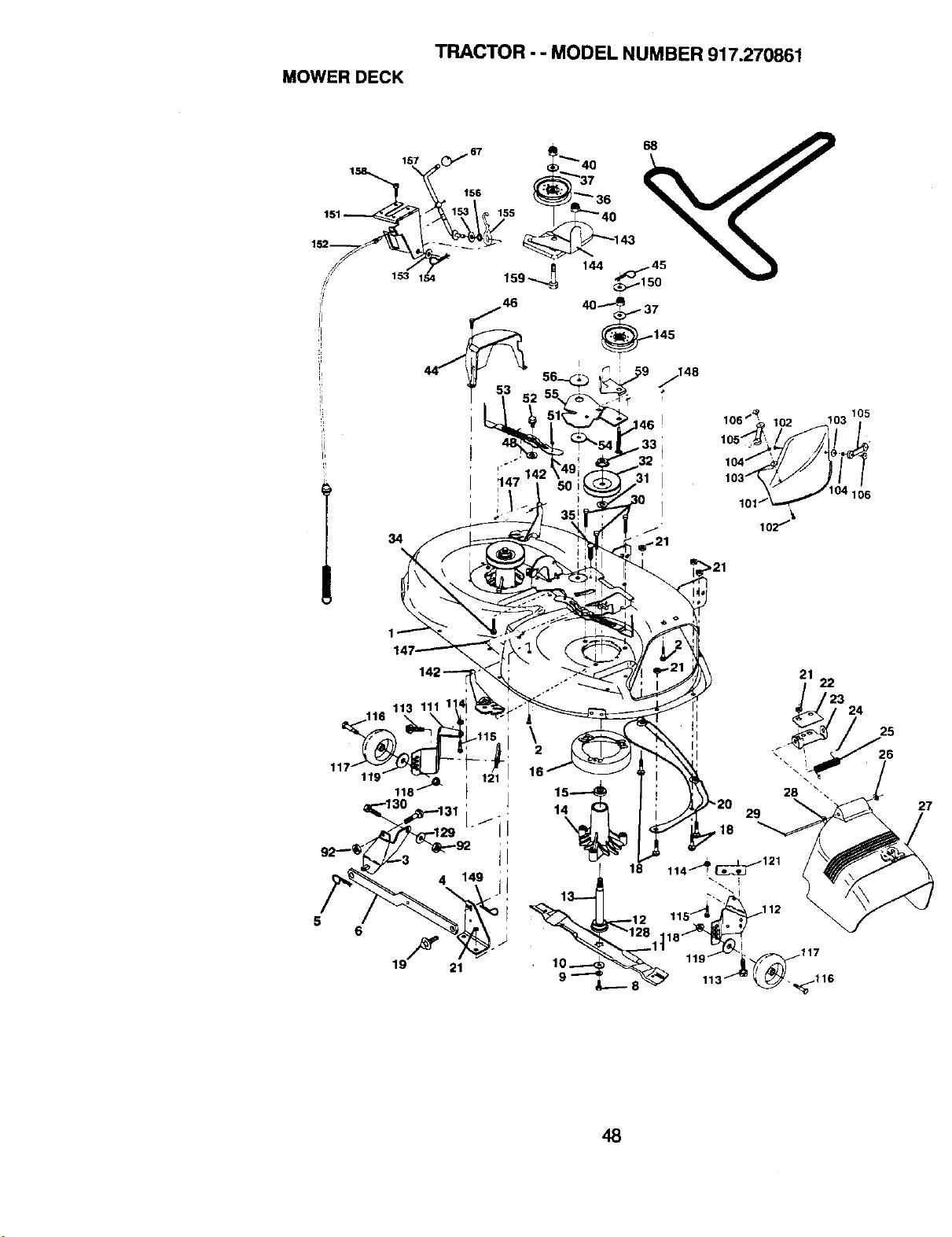
MOWER DECK
TRACTOR - - MODEL NUMBER 917.270861
34
47 1_
r,
106"_ 102 103 105
/ 104 106
1o2/_"
119
_I;223 24
29
,18
27
48
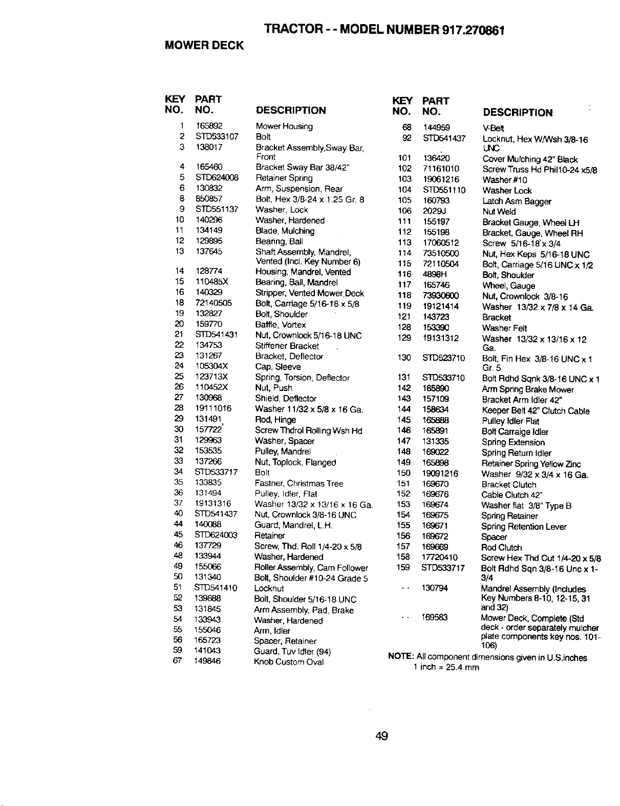
TRACTOR - - MODEL NUMBER 917.270861
MOWER DECK
KEY PART KEY PART
NO. NO. DESCRIPTION NO. NO.
1 165892 Mower Housing 68 144959
2 STD533107 Bolt 92 STD541437
3 138017 Bracket Assembly, Sway Bar,
Front 101 136420
4 165460 Bracket Sway Bar 38/42" 102 71161010
5 STO624008 P._tainer Spring 103 19061216
6 130832 Arm, Suspension, Rear 104 STD551110
8 850857 Bolt, Hex 3/8-24 x 1.25 Gr. 8 105 160793
9 STD551137 Washer, Lock 106 2029J
10 140296 Washer, Hardened 111 155197
11 134149 Blade, Mulching 112 155198
12 1298_5 Bearing, Ball 113 17060512
13 137645 Shaft Assembly, Mandrel, 114 73510500
Vented (Incl. Key Number 6) 115 72110504
14 128774 Housing, Mandrel, Vented 116 4898H
15 110485X Bearing, Bell, Mandrel 117 165746
16 140329 Stripper, Vented Mower Deck 118 7393(3600
18 72140505 Bolt, Carriage 5/16-15 x 5/8 119 19121414
19 132827 Bolt, Shoulder 121 143723
20 159770 Baffle, Vortex 128 15.3,390
21 STD541431 Nut, Crownlock5/16-18UNC 129 19131312
22 134753 Stiffener Bracket
23 131267 Bracket, Deflector 130 STD523716
24 105304X Cap, Sleeve
25 123713X Spring, Torsion, Deflector 131 STD533710
26 110452X Nut, Push 142 165890
27 130968 Shield, Deflector 143 157109
28 19111016 Washer 11/32 x 5/8 x 16 Ga. 144 158634
29 131491 Rod, Hinge 145 165888
30 157722' Screw Tb.drol P_lting Wsh Hd 146 165891
31 129963 Washer, Spacer 147 131335
32 153535 Pulley, Mandrel 148 169022
33 137266 Nut, Toplock, Flanged 149 165898
34 STD53.3717 Bolt 150 19091216
35 133835 Fasmer, Christmas Tree 151 169670
36 131494 Pulley, Idler, Flat 152 169676
37 19131316 Washer 13/32 x !3/16 x 16 Ga. 153 169674
40 STD541437 Nut, Crownlock 3/8-16 UNC 154 169675
44 140088 Guard, Mandrel, L.H. 155 169671
45 STD624003 Retainer 156 11Y)672
46 137729 Screw, Thd. Roll 1/4-20 x 5/8 157 169669
48 133944 Washer, Hardened 158 17720410
49 155066 RollerAssembly, Cam Follower 159 STD53,3717
50 131340 Bolt, Shoulder#10-24 Grade5
51 STD541410 Lecknut - - 130794
52 139888 Bolt, Shoulder 5/16-18 UNC
53 131845 Arm Assembty, Pad, Brake
- - 169583
54 133943 Washer, Hardened
55 155046 Arm, Idler
56 165723 Spacer, Retainer
59 141043 Guard, Tuv Idler (94)
67 149846 Knob Custom Oval
DESCRIPTION
V-Belt
Locknut, Hex W/Wsh 3/8-16
UNC
Cover Mulching42"Black
Screw Truss Hd Phil10-24 x5/8
Washer #10
Washer Lock
LatchAsm Bagger
NutWeld
Bracket Gauge, Wheel LH
Bracket,Gauge, Whsel RH
Screw 5/16-18"x 3/4
Nut,Has Keps 5/16-18 UNC
Bolt, Carriage5/16 UNC x 1/2
Bolt, Shoulder
Wheel, Gauge
Nut, Crownlock 3/8-16
Washer 13/32 x 7[8 x 14 Ga.
Bracket
Washer Felt
Washer 13/32 x 13/16 x 12
Ga.
Bofl, Fin He:<3/8-16 UNC × 1
Gr. 5
Bolt RdhdSqnk 3/8-16 UNC x 1
Arm SpnngBrake Mower
Bracket Arm Idler 42"
Keeper Belt42" Clutch Cable
Pulley Idler Flat
Bolt Carraige Idler
Spdng Extension
Spring Return Idler
Retainer Spring Yellow7inc
Washer 9/32 x 3/4 x 16 Ga.
Bracket Clutch
Cable Clutch 42"
Washer fiat 3/8" Type B
Spring Retainer
Spring Retention Lever
Spacer
RodClutch
Screw HexThd Cut 1/4-20x 5/8
BoltRdhdSqn 3/8-16 Unc x 1-
3/4
MandrelAssembly(includes
Key Numbers8-10, 12-15, 31
and32)
Mower Deck, Complete (Std
deck - orderseparatelymulcher
ptete componentskey hoe. 101-
106)
NOTE: All component dimensionsgiven in U.S.inches
1 inch = 25.4 mm
49
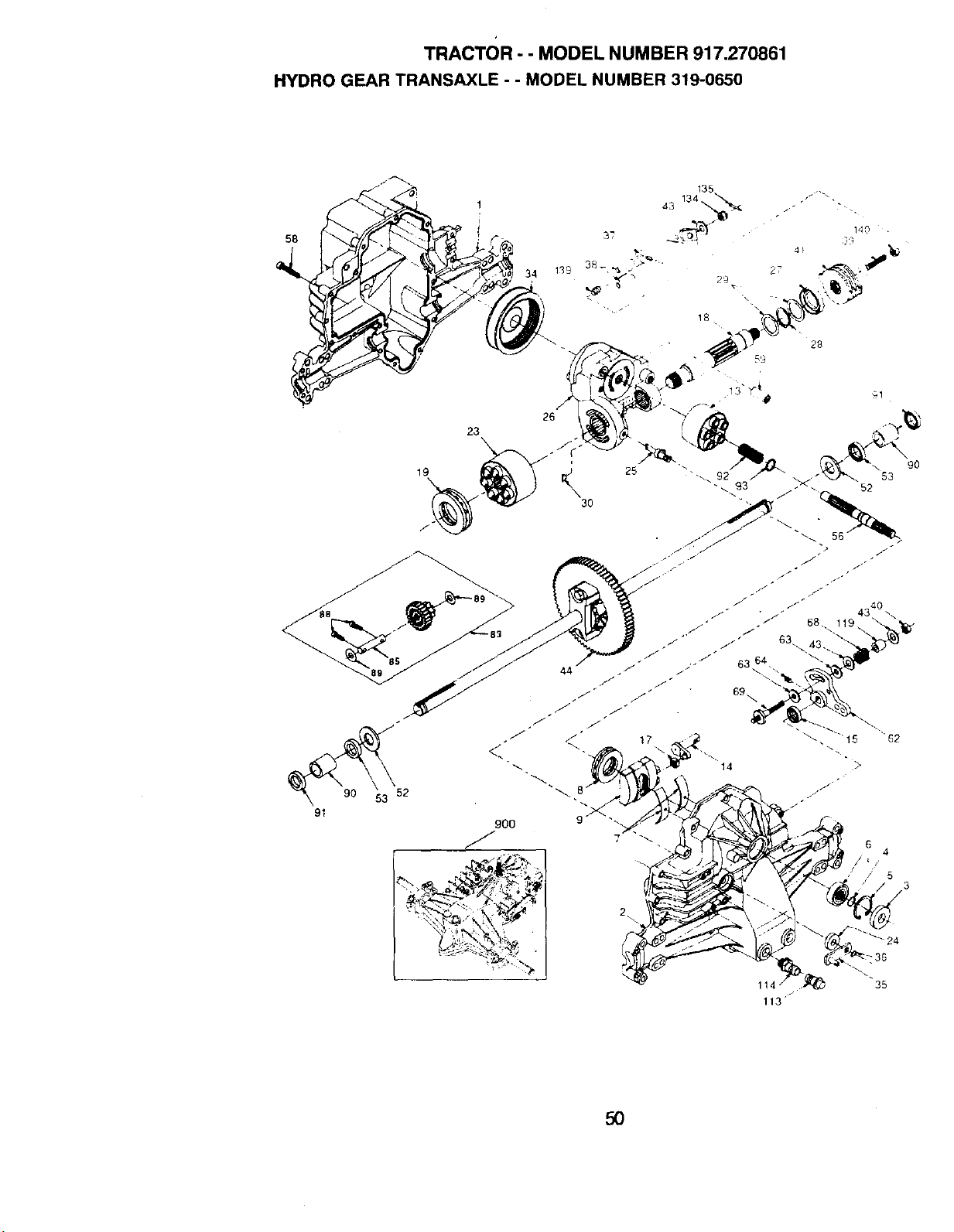
TRACTOR - - MODEL NUMBER 917.270861
HYDRO GEAR TRANSAXLE - - MODEL NUMBER 319-0650
58
91
23
19
30
90O
/ ,%,.
2•
6 4
t ,
/ / 5
3
35
113
50
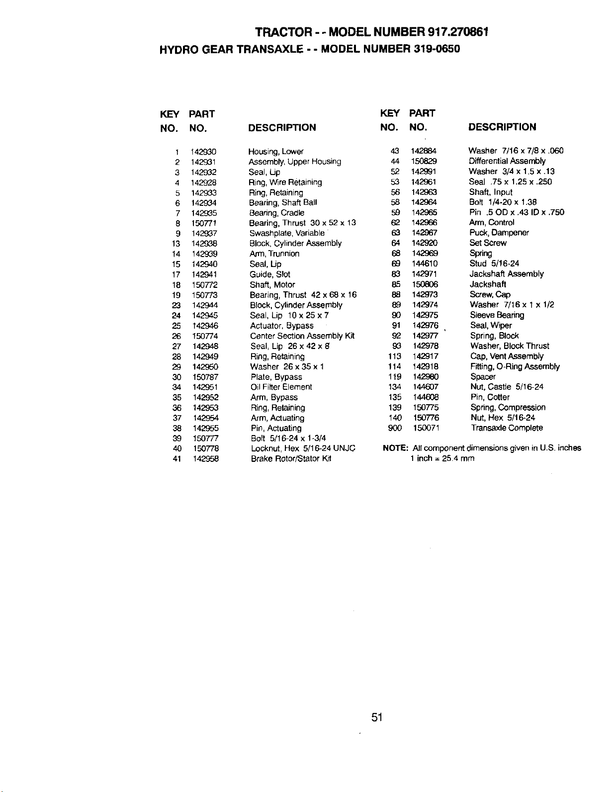
TRACTOR - - MODEL NUMBER 917.270861
HYDRO GEAR TRANSAXLE - - MODEL NUMBER 319-0650
KEY PART KEY PART
NO. NO. DESCRIPTION NO. NO. DESCRIPTION
1 142930 Housing, Lower 43 142884 Washer 7/16 x 7/8 x .060
2 142931 Assembly, Upper Housing 44 150829 Differential Assembly
3 142932 Seal, Up 52 142991 Washer 3/4 x 1.5 x .13
4 142928 Ring, W_re Retaining 53 142961 Seal .75 x 1.25 x .250
5 1429.33 Ring, Retaining 56 142963 Shaft, Input
6 142934 Bearing, Shaft Ball 58 142964 Bolt 1/4-20 x 1.38
7 142935 Beadng, Cradle 59 142965 Pin .50D x .43 ID x .750
8 150771 Bearing, Thrust 30 x 52 x 13 62 142966 Arm, Control
9 142937 Swashplate, Variable 63 142£67 Puck, Dampener
13 142938 Block, Cylinder Assembly 64 142920 SetScrew
14 142°J39 Arm, Trunnion 68 142968 Spring
15 142940 Seal, Up 69 144610 Stud 5/16-24
17 142941 Guide, Slot 83 142971 Jackshaft Assembly
18 150772 Shaft, Motor 85 150806 Jackshaft
19 150773 Bearing, Thrust 42 x 68 x 16 88 142973 Screw, Cap
23 142944 Block, Cylinder Assembly 89 142974 Washer 7/16 x 1 x 1/2
24 142945 Seal, Lip 10 x 25 x 7 90 142975 Sleeve Bearing
25 142946 Actuator, Bypass 91 142976 Seal, Wiper
26 150774 Center Section Assembly Kit £2 142977 Spring, Block
27 142948 Seal, Lip 26 x 42 x 8 93 142978 Washer, Block Thrust
28 142949 Ring, Retaining 113 142917 Cap, Vent Assembly
29 142£50 Washer 26 x 35 x 1 114 142918 Fitting, O-Ring Assembly
30 150787 Plate, Bypass 119 142980 Spacer
34 142951 Oil Filter Element 134 144607 Nut, Castle 5/16-24
35 142952 Arm, Bypass 135 144608 Pin, Cotter
36 142953 Ring, Retaining 139 150775 Spdng, Compression
37 142954 Arm, Actuating 140 150776 Nut, Hex 5/16-24
38 142955 Pin, Actuating 900 150071 Transaxle Complete
39 150777 Bolt 5/16-24 x 1-3/4
40 150778 Locknut, Hex 5/16-24 UNJC NOTE: All component dimensions given in U.S. inches
41 142958 Brake Rotor/Stator Kit 1 inch = 25.4 mm
51
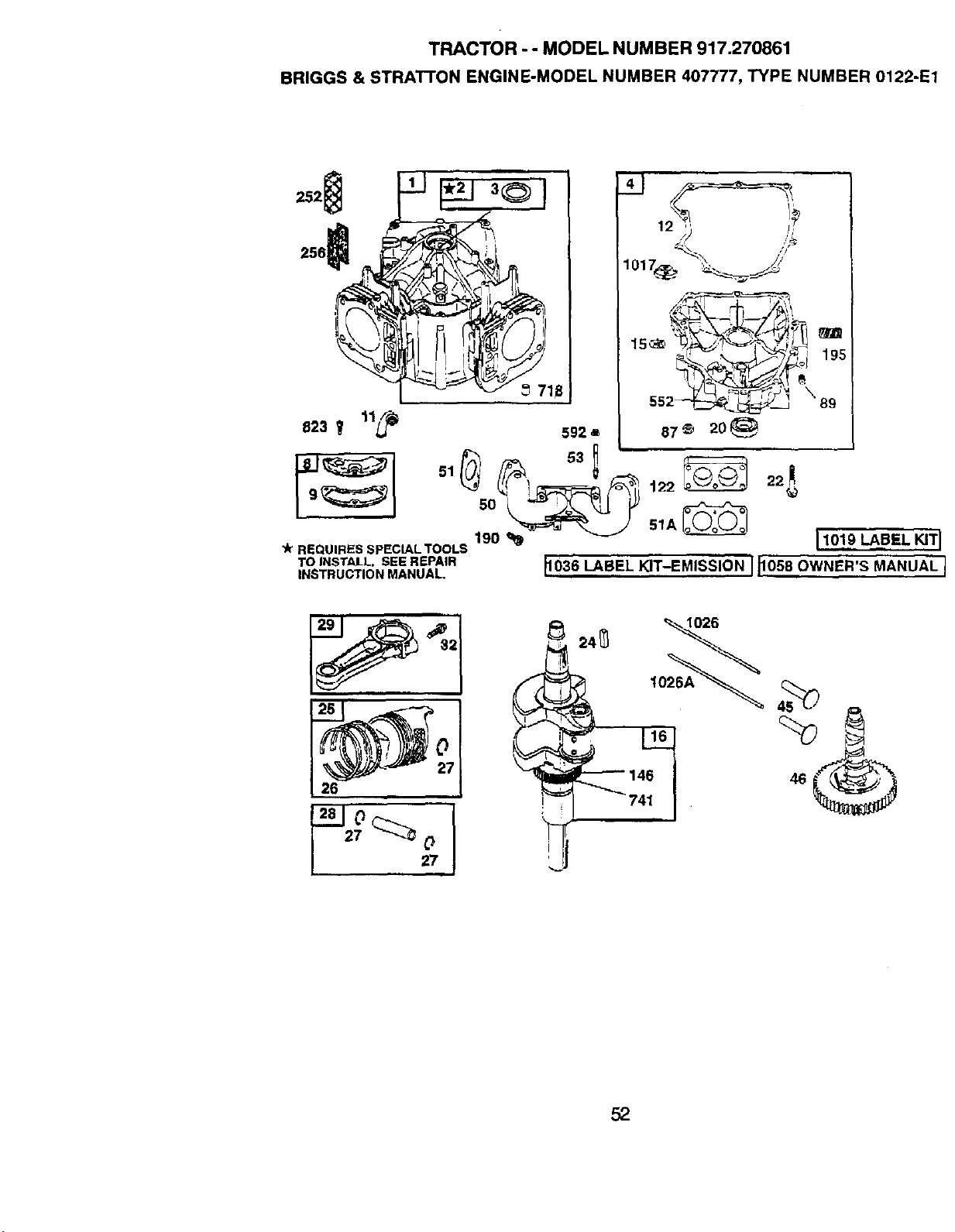
TRACTOR - - MODEL NUMBER 917.270861
BRIGGS & STRATrON ENGINE-MODEL NUMBER 407777, TYPE NUMBER 0122-E1
256_
823 _ 11L_
592 a
19o_ 1lOl_9LABEL_TI
REQUIRESSPECIALTOOLS
TOINSTALL.SEEREPAIR _1036LABEL KIT-EMISSION I _1058OWNER'S MANUAL I
INSTRUCTIONMANUAL.
22!
26
1O26
52
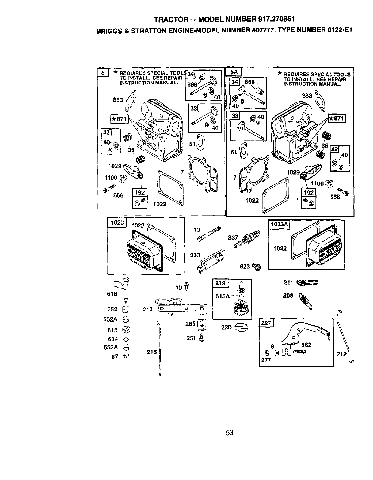
TRACTOR - - MODEL NUMBER 917.270861
BRIGGS & STRATTON ENGINE-MODEL NUMBER 407777, TYPE NUMBER 0122-E1
"51 -k REQUIRES SPECIAL TOOLI
TO INSTALL SEE REPAIR
INSTRUCTION MANUAL,
9883 _
1029
7
_ lo22
,i
1022
,k-REQUIRES SPECIAL TOOL,_
TO INSTALL. SEE REPAIR
INSTRUCTION MANUAL
102_:_
,j
I
I
616
552
552A
615
634 '_
552A
87
265
351
216
220
211
209
6 _J-_l_=,_'
277
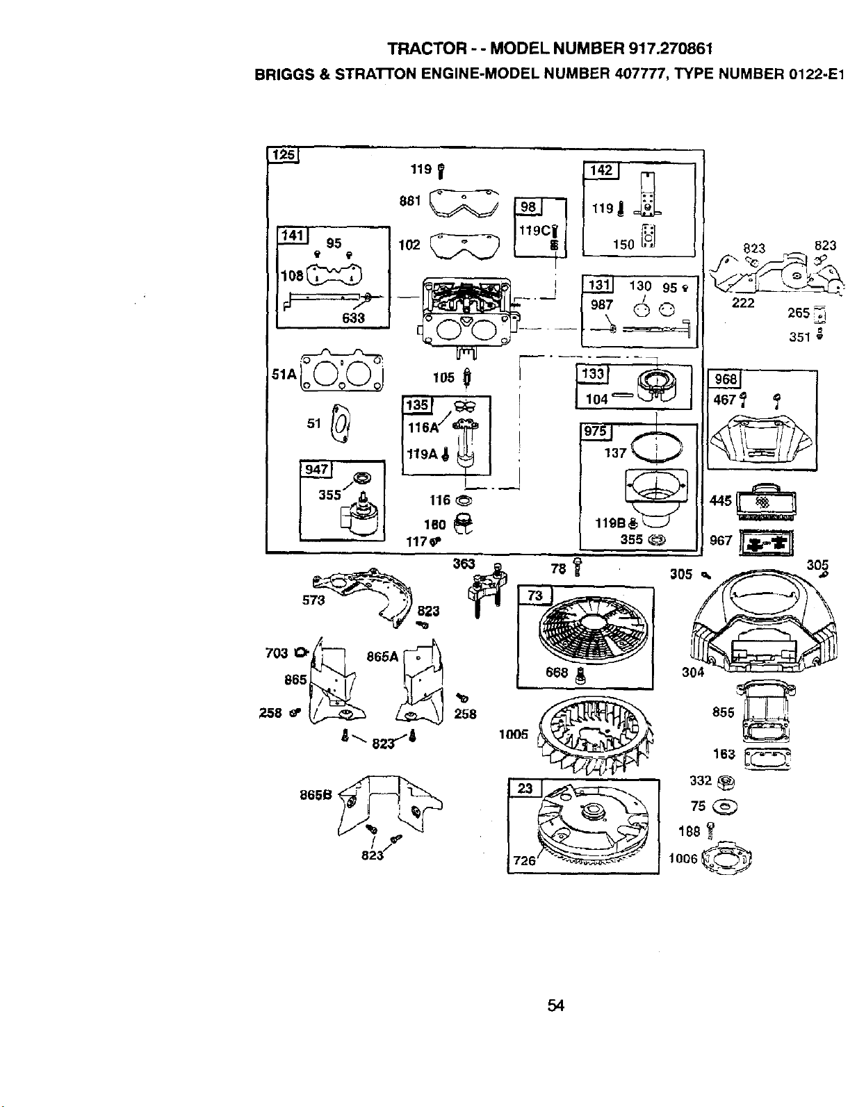
TRACTOR - - MODEL NUMBER 917.270861
BRIGGS & STRATrON ENGINE-MODEL NUMBER 407777, TYPE NUMBER 0122-E1
l___j
1411 95
108_
5%1
,,°, t_ '
,02_ I ,5o
____j _ 13o,5,
[987 _©
lo50
116
160 _
117_
97__JF_
137 _,,,/
119B_
355
7o3o_ 8°°,_
_,-_e2_...--4
258
IO05
i
823 823
222
265 _
351 g
467f f
967
305
855_.
163
332 _:_
75
188
1006
54
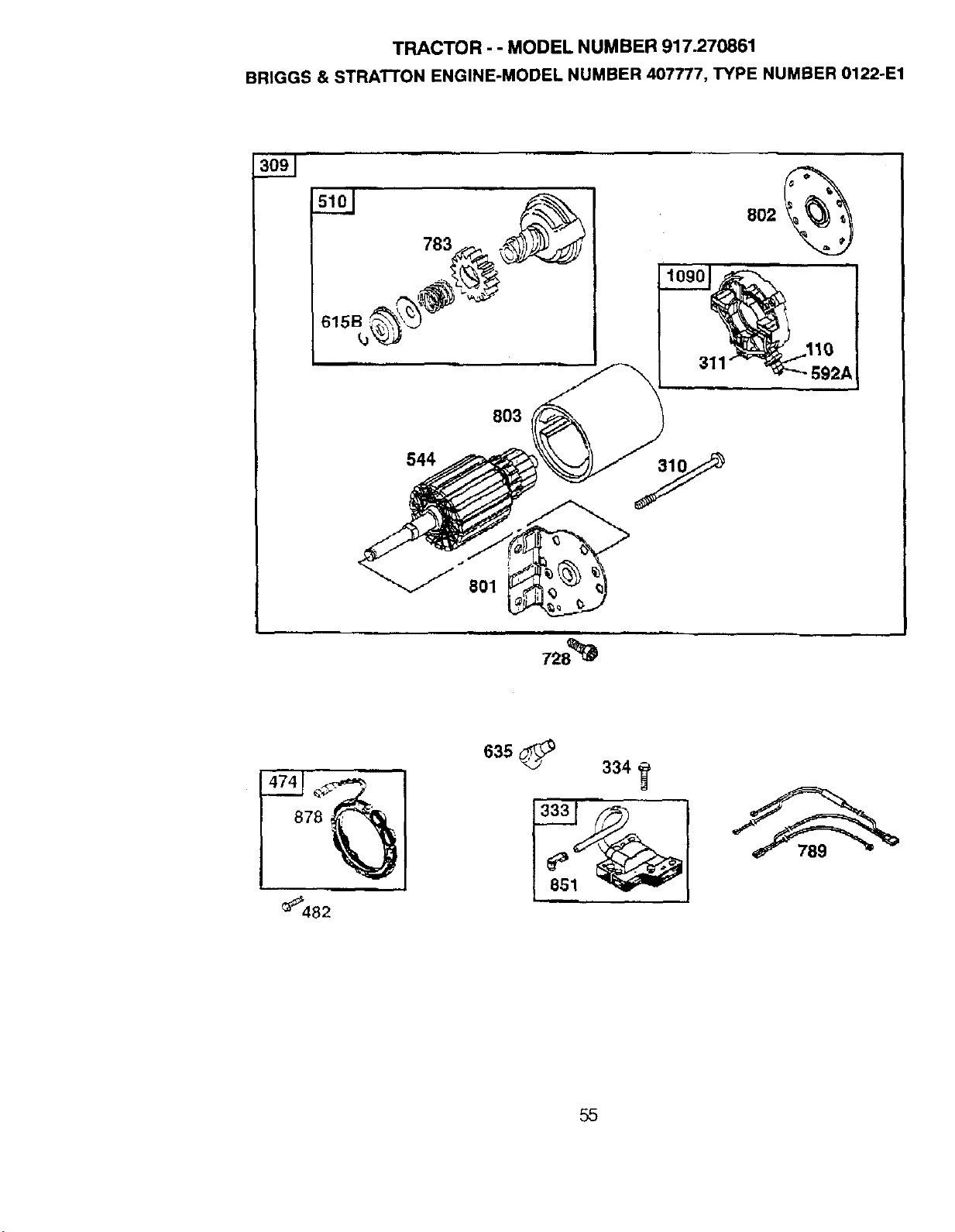
TRACTOR - - MODEL NUMBER 917.270861
BRIGGS & STRATTON ENGINE-MODEL NUMBER 407777, TYPE NUMBER 0122-E1
311 t
_92A
803
544
=,
728_
878
_482
851
334
55
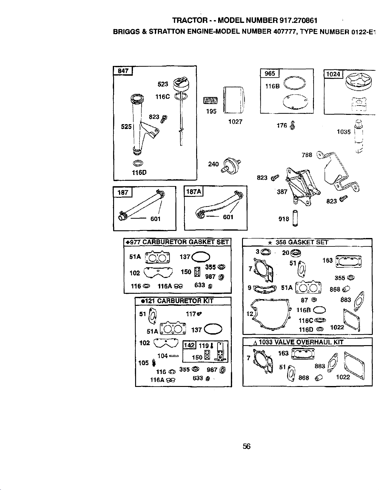
TRACTOR- - MODEL NUMBER 917.270861
BRIGGS & STRATTON ENGINE-MODEL NUMBER 407777, TYPE NUMBER 0122-E1
523
116C
823 _I_
525
116D
_ 60!
195
1027
116B O
176_ 10_5
r
4.977 CARBURETOR GASKET SET
51A _ 137 0
102 _ 150_ 355_
967
116_ 116A_ 633 @
e121 CARBURETOR KIT
51 _, 117_
°lA 1 70
105
116_ 355@ 987@
116A'_I_ 633 @ .
.358 GASKET SET
s_. 2o@
7_. 51_ 163_s55,_
1 11sB0 J
116C_
116D _ 102
A 1033 VALVE OVERHAUL KIT
51 _ 883
868 _ o
56
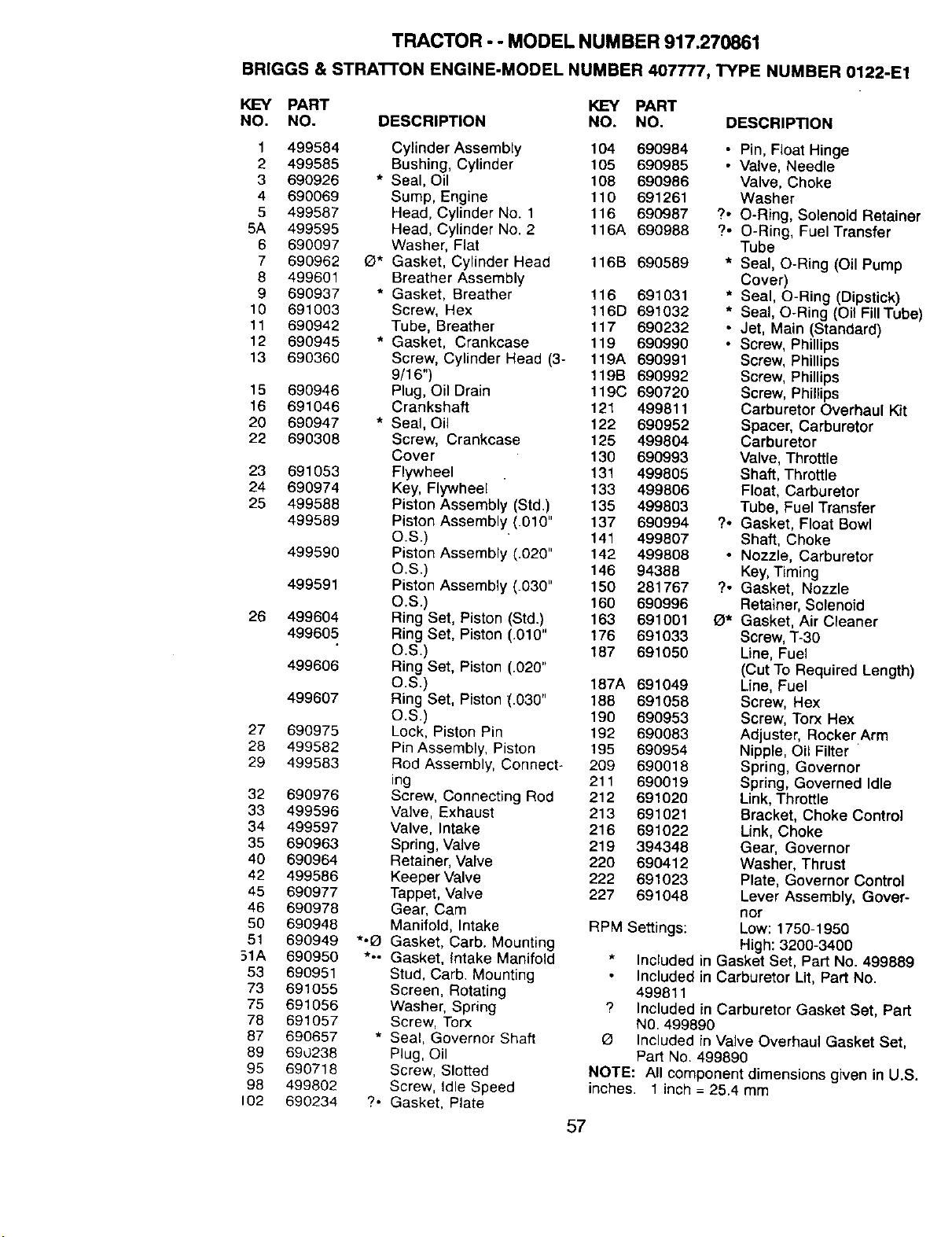
TRACTOR - - MODEL NUMBER 917.270861
BRIGGS & STRATTON ENGINE-MODEL NUMBER 407777, TYPE NUMBER 0122-E1
KEY PART KEY PART
NO. NO. DESCRIPTION NO. NO. DESCRIPTION
1 499584 Cylinder Assembly 104 690984
2 499585 Bushing, Cylinder 105 690985
3 690926 * Seal, Oil 108 690986
4 690069 Sump, Engine 110 691261
5 499587 Head, Cylinder No. 1 116 690987
5A 499595 Head, Cylinder No. 2 116A 690988
6 690097 Washer, Flat
7 690962 O* Gasket, Cylinder Head 116B 690589
8 499601 Breather Assembly
9 690937 * Gasket, Breather 116 691031
10 691003 Screw, Hex 116D 691032
11 690942 Tube, Breather 117 690232
12 690945 * Gasket, Crankcase 119 690990
13 690360 Screw, Cylinder Head (3- 119A 690991
9/16") 119B 690992
15 690946 Plug, Oil Drain 119C 690720
16 691046 Crankshaft 121 499811
20 690947 * Seal, Oil 122 690952
22 690308 Screw, Crankcase 125 499804
Cove r 130 690993
23 691053 Flywheel 131 499805
24 690974 Key, Flywheel 133 499806
25 499588 Piston Assembly (Std.) 135 499803
499589 Piston Assembly (.010" 137 690994
O.S.) 141 499807
499590 Piston Assembly (.020" 142 499808
O.S.) 146 94388
499591 Piston Assembly (.030" 150 281767
O.S.) 160 690996
26 499604 Ring Set, Piston (Std.) 163 691001
499605 Ring Set, Piston (.010" 176 691033
O.S.) 187 691050
499606 Ring Set, Piston (.020"
O.S.) 187A 691049
499607 Ring Set, Piston (.030" 188 691058
O.S.) 190 690953
27 690975 Lock, Piston Pin 192 690083
28 499582 Pin Assembly, Piston 195 690954
29 499583 Rod Assembly, Connect- 209 690018
ing 211 690019
32 690976 Screw, Connecting Rod 212 691020
33 499596 Valve, Exhaust 213 691021
34 499597 Valve, Intake 216 691022
35 690963 Spring, Valve 219 394348
40 690964 Retainer, Valve 220 690412
42 499586 Keeper Valve 222 691023
45 690977 Tappet, Valve 227 691048
46 690978 Gear, Cam
50 690948 Manifold, Intake
51 690949 *'_ Gasket, Carb. Mounting
51A 690950 *.- Gasket, Intake Manifold
53 690951 Stud, Carb. Mounting
73 691055 Screen, Rotating
75 691056 Washer, Spring
78 691057 Screw, Torx
87 690657 * Seal, Governor Shaft
89 690238 Plug, Oil
95 690718 Screw, Slotted
98 499802 Screw, Idle Speed
102 690234 ?. Gasket, Plate
• Pin, Float Hinge
• Valve, Needle
Valve, Choke
Washer
?. O-Ring, Solenoid Retainer
?. O-Ring, Fuel Transfer
Tube
* Seal, O-Ring (Oil Pump
Cover)
* Seal, O-Ring (Dipstick)
* Seal, O-Ring (Oil Fill Tube)
• Jet, Main (Standard)
• Screw, Phillips
Screw, Phillips
Screw, Phillips
Screw, Phillips
Carburetor Overhaul Kit
Spacer, Carburetor
Carburetor
Valve, Throttle
Shaft, Throttle
Float, Carburetor
Tube, Fuel Transfer
?. Gasket, Float Bowl
Shaft, Choke
• Nozzle, Carburetor
Key, Timing
?. Gasket, Nozzle
Retainer, Solenoid
e* Gasket, Air Cleaner
Screw, T-30
Line, Fuel
(Cut To Required Length)
Line, Fuel
Screw, Hex
Screw, Torx Hex
Adjuster, Rocker Arm
Nipple, Oil Filter
Spring, Governor
Spring, Governed Idle
Link, Throttle
Bracket, Choke Control
Link, Choke
Gear, Governor
Washer, Thrust
Plate, Governor Control
Lever Assembly, Gover-
nor
RPM Settings: Low: 1750-1950
High: 3200-3400
* Included in Gasket Set, Part No. 499889
Included in Carburetor Lit, Part No.
499811
? Included in Carburetor Gasket Set, Part
NO.499890
Included in Valve Overhaul Gasket Set,
Part No. 499890
NOTE: All component dimensions given in U.S.
inches. 1 inch = 25.4 mm
57
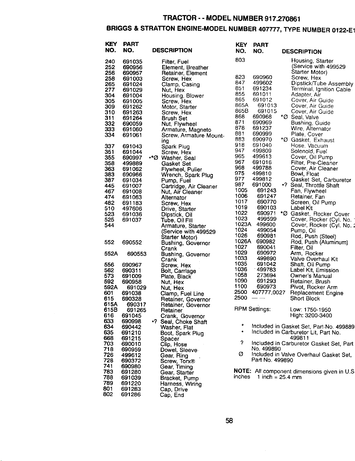
TRACTOR - - MODEL NUMBER 917.270861
BRIGGS & STRAI-rON ENGINE-MODEL NUMBER 407777, TYPE NUMBER 0122.
KEY PART KEY PART
NO. NO. DESCRIPTION NO. NO. DESCRIPTION
240 691035
252 690956
256 690957
258 691003
265 691024
277 691029
304 691004
305 691005
309 691262
310 691263
311 691264
332 690059
333 691060
334 691061
337 691043
351 691044
355 690997 .*0
358 499889
363 691062
383 690966
387 691034
445 691007
467 691008
474 691063
462 691183
510 497606
523 691036
525 691037
544
552 690552
552A 690553
556 690967
562 690311
573 691009
592 690958
592A 691029
601 691038
615 690328
615A 690317
615B 691265
616 691045
633 690996
634 690442
635 691210
668 691215
703 690010
718 690959
726 499612
728 690372
741 690980
783 691280
788 691039
769 691220
801 691283
802 691286
Filter, Fuel 803 Housing, Starter
Element, Breather (Service with 499529
Retainer, Element Starter Motor)
Screw, Hex 823 690960 Screw, Hex
847 499602 Dipstick/Tube Asseml
Clamp, Casing
Nut, Hex 851 691234 Terminal, Ignition Cab
Housing, Blower 855 691011 Adapter, Air
Screw, Hex 865 691012 Cover, Air Guide
Motor, Starter 865A 691013 Cover, Air Guide
Screw, Hex 865B 691015 Cover, Air Guide
868 690968 *O Seal, Valve
Brush Set
Nut, FLywheel 871 690969 Bushing, Guide
878 691237 Wire, Alternator
Armature, Magneto
Screw, Armature Mount- 881 690999 Plate, Cover
883 690970 *O Gasket, Exhaust
ing 918 691040 Hose, Vacuum
Spark Plug
Screw, Hex 947 499809 Solenoid, Fuel
Washer, Seal 965 499613 Cover, Oil Pump
Gasket Set 967 691016 Filter, Pre-Cleaner
968 499788 Cover, Air Cleaner
_renheel, Puller
ch, Spark Plug 975 499810 Bowl, Float
Pump, Fuel 977 499812 Gasket Set, Carbureb
Cartridge, Air Cleaner 987 691000 .? Seal, Throttle Shaft
Nut, Air Cleaner 1005 691243 Fan, F]ywheel
Alternator 1006 691247 Retainer, Fan
Screw, Hex 1017 690770 Screen, Oil Pump
1019 690103 Label Kit
Drive, Starter 1022 690971 *O Gasket, Rocker Cove
Dipstick, Oil 1023 499599 Cover, Rocker (Cyl. N
Tube, Oil Fill
Armature, Starter 1023A 499600 Cover, Rocker (Cyl. N
1024 499054 Pump, Oil
_Service with 499529
tarter Motor) 1026 690981 Rod, Push (Steel)
Bushing, Governor 1026A 690982 Rod, Push (Aluminum)
Crank 1027 690041 Filter, Oil
Bushing, Governor 1029 690972 Arm, Rocker
Crank 1033 499890 Valve Overhaul Kit
Screw, Hex 1035 691042 Shaft, Oil Pump
1036 499783 Label Kit, Emission
Bolt, Carriage
Plate, BLack 1058 273694 Owner's Manual
Nut, Hex 1090 691293 Retainer, Brush
Nut, Hex 1100 690973 Pivot, Rocker Arm
Clamp, Fuel Une 2500 407777,0027 Replacement Engine
Retainer, Governor 2500 ---- Short Block
Retainer, Governor RPM Settings: Low: 1750-1950
Retainer
Crank, Governor High: 3200-3400
o? Seal, Choke Shaft
Washer, Flat * Included in Gasket Set, Part,No. 499_
Boot, Spark Plug Included in Carburetor Lit, Part No.
499811
Spacer "_ Included in Carburetor Gasket Set, P
Clip, Hose
Dowel, Sleeve No. 499890
Gear, Ring Q Included in Valve Overhaul Gasket S_
Screw, Torx® Part No. 499890
Gear, Timing
Gear, Starter NOTE: All component dimensions given in L
Bracket, Pump inches 1 inch = 25.4 mm
Harness, Wiring
Cap, Drive
Cap, End
58

SUGGESTED GUIDE FOR SIGHTING SLOPES FOR SAFE OPERATION
I ""
SIGHTING
GUIDE
ONLY RIDE UP AND DOWN HILL,
NOT ACROSS HILL
i_ _% Operate your Tractor up and down the face of slopes (not
i_| _LJk greater than 15 ), never across the face. Make turns gradu-
i| _ ally to prevent tipping or loss of control. Exercise extreme
caution when changing direction on slopes.

For in-home major brand repair service:
Call 24 hours a day, 7 days a week
1-800-4-MY-HOME s_ (1-800-469-4663)
Para pedir servicio de reparacibn a domicilio
1-800-676-5811
In Canada for all your service and parts needs call
Au Canada pour tout le service ou les pieces
1-800-665-4455
For the repair or replacement parts you need:
Call 6 am - 11 pm CST, 7 days a week
PartsDirect sM
1-800-366-PART (1-800-366-7278)
Para ordenar piezas con entrega a domicilio
1-800-659-7084
For the location of a Sears Parts and Repair Center
in your area:
Call 24 hours a day, 7 days a week
1-800-488-1222
For information on purchasing a Sears Maintenance
Agreement or to inquire about an existing Agreement:
Call 9 am - 5 pm, Monday - Saturday
1-800-827-6655
SWARS
Home Central
170089 Rev. 1 7.13.99 TR Printed in U.S.A,


