No: 341086 – 03/15
Pass & Seymour
®
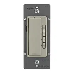
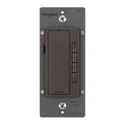
Time Switch 4-Button Preset
Interrupteur horaire à 4 boutons préréglé
Interruptor Temporizado Preajuste de 4 Botones
Installation Instructions • Instrucciones de Instalación • Notice d’Installation
Catalog Number(s) • Numéro(s) de Catalogue • Les Numéros de Catalogue: RT2
Country of Origin: Made in China • Pays d’origine: Fabriqué en Chine • País de origen: Hecho en China
DESCRIPTION AND OPERATION
The RT2 is a time switch that turns OFF the connected light or fan when the selected time expires. An indicator
light illuminates when the switch is OFF. When selecting a time delay of 20 min or more, as time expires, the button
LED’s will move through the next available time delay, always giving an indication of the amount of time left before
the time delay expires. One minute before each time delay transition, the active button LED will ash, providing the
user an indication of the transition.
Manual ON
Turn ON the connected light or fan by pressing the desired time button, or the ON/OFF button. If you press the
ON/OFF button, it activates the timer that was last used.
Manual OFF
While a timer is active, you can press the ON/OFF button to turn OFF the connected light or fan without delay.
Changing the selected time
If you decide that you need more or less time than you originally selected, restart the time switch by pressing the
button that matches the amount of time you think you’ll need.
INSTALLATION AND WIRING
WARNING
Disconnect power to the wall switch box by turning OFF
the circuit breaker or removing the fuse for the circuit before
installing the RT2, replacing lamps, or doing any electrical work.
1. Prepare the switch box.
After the power is turned OFF at the circuit breaker box, remove the
existing wall plate and mounting screws. Pull the old switch out from
the wall box.
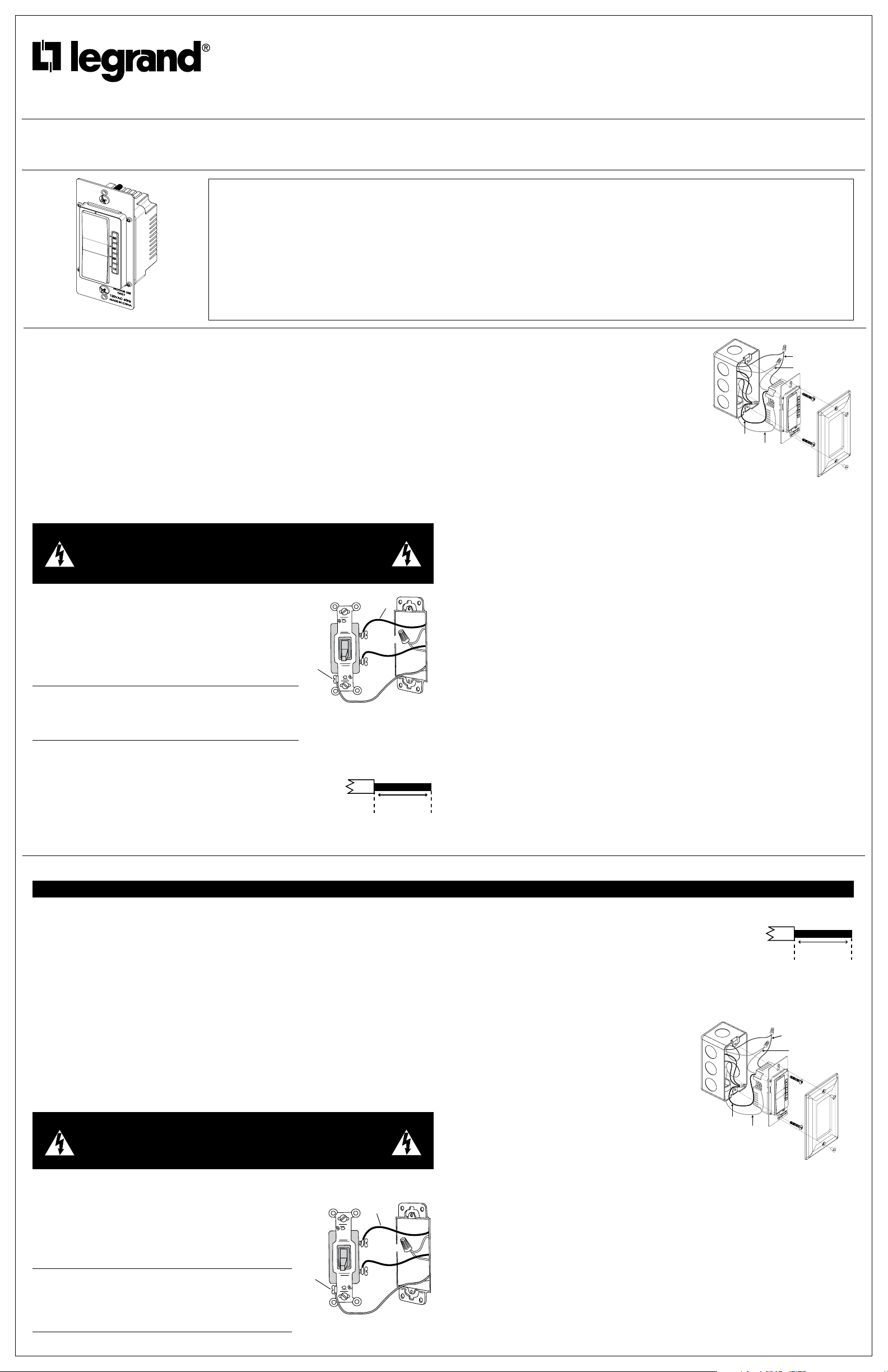
2. Identify the type of circuit.
In a Single Pole Circuit (see Fig. 1), two single wires connect to two
screws on the existing switch. A ground wire may also be present and
connected to a ground terminal on the old switch. A neutral wire should
also be present in the wall box.
CAUTION
For your safety: Connecting a proper ground to the time switch
provides protection against electrical shock in the event of certain
fault conditions. If a proper ground is not available, consult
with a qualied electrician before continuing installation.
Only connect the RT2 to a Single Pole Circuit. The RT2 is not suitable for 3-way switching. If the existing
wiring does not match the description for a Single Pole Circuit, you should consult with a qualied electrician.
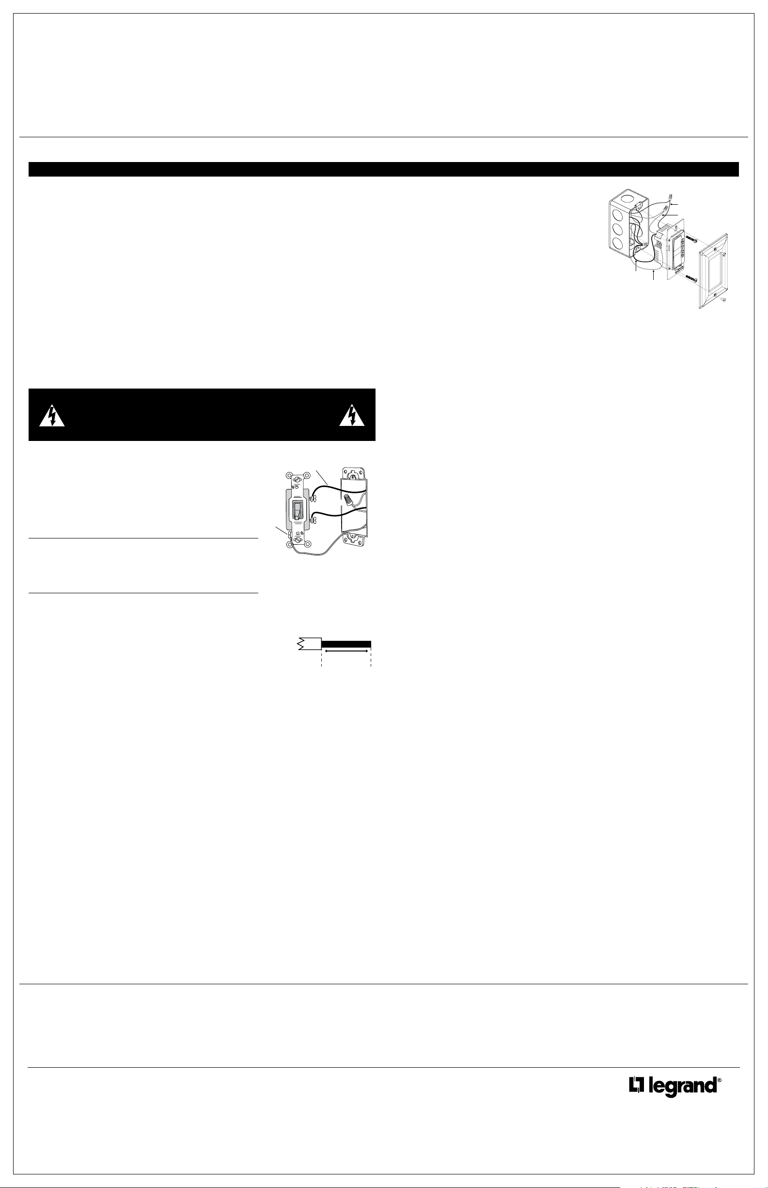
3. Prepare the Wires.
Tag the wires currently connected to the existing switch, so that they can be
identied later. Disconnect the wires. Make sure the insulation is stripped off the
wires to expose their copper cores to the length indicated by the “Strip Gage,” in
Fig. 2 (approximately 1/2 inch).
4. Wire the time switch.
Twist the existing wires together with the wire leads on the time
switch as indicated in the drawing. Cap them securely using the
wire nuts provided. See Fig 3.
• Connect the green or non-insulated (copper) GROUND wire
from the circuit to the GROUND terminal on the RT2.
• Connect the power wire from the circuit (HOT) to the black
wire on the RT2.
• Connect the power wire to the lamp or fan (LOAD) to the
red wire on the RT2.
• Connect the NEUTRAL wires from the circuit to the white
wire on the RT2.
5. Put the RT2 in the wall box with the time selection buttons
positioned above the ON/OFF button.
Secure it to the wall box with the screws provided.
6. Install cover plates.
Install industry standard decorator wall switch cover plate
(not included).
7. Restore power to the circuit.
Turn on the breaker or replace the fuse.
TROUBLESHOOTING
To test the time switch:
The light behind the ON/OFF button should be ON when the switch is OFF.
Press the ON/OFF button. The connected light or fan comes ON. The connected light or fan should turn OFF in the
number of minutes indicated by the time selection indicator light. You can turn it OFF sooner by pressing the ON/
OFF button again.
Light or fan will not turn ON (lighted switch is ON):
Press ON/OFF button. The connected light or fan should turn ON. If not:
• Check the light bulb and/or motor switch on the fan mechanism.
• Turn OFF power to the circuit then check wire connections.
Light or fan will not turn ON (lighted switch is OFF and no indicator is ON):
• Shade the switch from external light to make sure that none of the indicator lights are ON.
• Check the light bulb and/or motor switch on the fan mechanism.
• Make certain that the circuit breaker is ON and functioning.
• Turn OFF power to the circuit then check wire connections.
• Call 1.800.223.4185 for technical support.
Light or fan will not turn OFF:
• Press the ON/OFF button. If connected light or fan does not turn OFF, turn OFF power to the circuit then
check wire connections.
COVER PLATES
Legrand RT wall switches t behind industry standard decorator style switch cover plates.
SPECIFICATIONS
Load (Single Pole Circuit)
Fan Motor...........................................................................1/6HP
Environment ...........................................................Indoor use only
Humidity..................................................95% RH, non-condensing
Tools Needed
• Insulated Screwdriver
• Wire Strippers
Voltage.....................................................................120VAC, 60HZ
Incandescent, uorescent lamp, E-ballast, MLV,
ELV, CFL, LED ............................................................ 0 – 800VA
Time Delay ..................................................10, 20, 40, 60 minutes
Operating Temperature ............................32° to 131°F (0° to 55°C)
SPÉCIFICATIONS
Charge (circuit unipolaire)
Moteur de ventilateur ............................................................1/6 HP
Environnement ......................... Utilisation en intérieur uniquement
Humidité ........................................... 95 % HR, sans condensation
Outils nécessaires
• Tournevis isolé
• Dénudeurs de l
Tension ................................................................120 V c.a., 60 Hz
Lampe incandescente, lampe uorescente, E-ballast, lampe
magnétique basse tension, lampe très basse tension, lampe
uo-compacte, DEL ...................................................0 – 800 VA
Temporisation ..........................................10, 20, 40 ou 60 minutes
Température de fonctionnement ..............0° à 55° C (32° à 131° F)
ESPECIFICACIONES
Carga (Circuito unipolar)
Un motor ............................................................................1/6HP
Condiciones de operación ....................Solo para uso en interiores
Humedad ................................................95% RH, non-condensing
Herramientas necesarias
• Desatornillador con aislamiento
• Peladora de alambre/cable
Voltaje .....................................................................120VAC, 60HZ
Lámparas incandescentes, uorescentes,
E-ballast, MLV, ELV, CFL, LED .................................. 0 – 800VA
Retardo de Apagado....................................10, 20, 40, 60 minutos
Temperatura .....................................entre 32° y 131°F (0° y 55°C)
INSTRUCTIONS EN FRANÇAIS
DESCRIPTION ET FONCTIONNEMENT
Le RT2 est un interrupteur horaire permettant d’éteindre la lampe ou le ventilateur raccordé(e) lorsque la durée
sélectionnée arrive à terme. Un voyant est allumé lorsque l’interrupteur est éteint. Lorsqu’une durée égale ou
supérieure à 20 est sélectionnée, les DEL des interrupteurs s’allumeront les unes après les autres, indiquant ainsi
le temps restant avant la n du délai. Une minute avant le passage à la durée suivante, la DEL de l’interrupteur actif
clignotera an d’informer l’utilisateur de la transition.
MARCHE Manuelle
Allumez la lampe ou le ventilateur raccordé(e) en appuyant sur la durée souhaitée ou sur l’interrupteur MARCHE/
ARRÊT (ON/OFF). Si vous optez pour l’interrupteur MARCHE/ARRÊT (ON/OFF), la dernière durée en date
sera appliquée.
ARRÊT manuel
Lorsque la minuterie est activée, vous pouvez appuyer sur l’interrupteur MARCHE/ARRÊT (ON/OFF) an d’éteindre
immédiatement la lampe ou le ventilateur raccordé(e).
Changement de la durée choisie
Si la durée initialement sélectionnée ne vous convient plus, redémarrez l’interrupteur horaire en appuyant sur le
bouton qui correspond à la durée dont vous pensez avoir besoin.
INSTALLATION ET BRANCHEMENT
ATTENTION
Mettez le boîtier d’interrupteur mural hors tension en coupant le
disjoncteur de circuit ou en retirant le fusible du circuit avant d’installer
le RT2, de remplacer des lampes ou d’effectuer des travaux d’électricité.
1. Préparez le boîtier d’interrupteur.
Une fois que le courant est COUPÉ au niveau du disjoncteur de circuit,
retirez la plaque murale et les vis de montage existantes. Enlevez
l’ancien interrupteur du boîtier mural.
2. Identifiez le type de circuit.
Dans un circuit unipolaire (voir Fig. 1), deux ls simples sont raccordés
aux deux vis de l’interrupteur existant. Un l de terre peut également
être présent et raccordé à la borne de terre de l’ancien interrupteur.
Un l neutre peut également être présent dans le boîtier mural.
ATTENTION
Pour votre sécurité : la mise à la terre appropriée de
l’interrupteur horaire fournit une protection contre les décharges
électriques dans le cas de certaines défaillances. Si une
mise à la terre appropriée n’est pas disponible, consultez
un électricien qualié avant de continuer l’installation.
Le RT2 doit être raccordé à un circuit unipolaire uniquement.
Il ne convient pas pour un système tridirectionnel. Si le branchement
existant ne correspond pas à la description fournie pour un circuit unipolaire,
consultez un électricien qualié.
3. Préparez les fils.
Marquez les ls actuellement raccordés à l’interrupteur existant an de
pouvoir les identier par la suite. Débranchez les ls. Assurez-vous que
l’isolant est enlevé des ls pour mettre à nu leurs conducteurs en cuivre
sur la longueur indiquée par le « Gabarit de dénudage » de la Fig. 2
(environ 12,7 mm (1/2 po)).
4. Branchez l’interrupteur horaire.
• Entortillez les ls existants et les ls conducteurs
de l’interrupteur horaire, comme indiqué sur l’image.
Posez solidement les capuchons de connexion fournis.
Voir Fig. 3.
• Raccordez le l de TERRE (cuivre) non isolé ou vert du
circuit à la borne de TERRE du RT2.
• Raccordez le l d’alimentation du circuit (SOUS TENSION)
au l noir du RT2.
• Raccordez le l d’alimentation de la lampe ou du ventilateur
(CHARGE) au l rouge du RT2.
• Raccordez les ls NEUTRES du circuit au l blanc du RT2.
5. Placez le RT2 dans le boîtier mural en positionnant
les boutons de sélection de durée au-dessus de l’interrupteur
MARCHE/ARRÊT (ON/OFF).
Fixez-le sur le boîtier mural à l’aide des vis fournies.
6. Montez les caches.
Montez le cache d’interrupteur mural Decorator aux normes
du secteur (non fourni).
7. Remettez le circuit sous tension.
Enclenchez le disjoncteur ou le fusible.
DÉPANNAGE
Pour tester le commutateur temporisé :
L’ampoule située derrière l’interrupteur MARCHE/ARRÊT (ON/OFF) doit être allumée lorsque l’interrupteur
est éteint.
Appuyez sur l’interrupteur. La lampe ou le ventilateur raccordé(e) s’allume. La lampe ou le ventilateur raccordé(e)
doit s’éteindre à la n du temps indiqué par le voyant. Vous avez la possibilité d’éteindre l’appareil plus tôt en
appuyant de nouveau sur l’interrupteur MARCHE/ARRÊT (ON/OFF).
Black: HOT (power
from circuit box)
Red: LOAD (power
to lamp or fan)
White: NEUTRAL
Green:
GROUND Terminal
Fig. 3. Switch Orientation, Wires
Connections and Wall Box Assembly
Strip Gage
1/2"
12.7 mm
Fig. 2. Wire Stripping
HOT (power from
circuit box)
LOAD
(power
to lamp)
NEUTRAL
Ground
Fig. 1. Typical Single Pole
Switch Wiring
SOUS TENSION
(alimentation provenant
du disjoncteur
de circuit)
CHARGE
(alimentation
fournie à
la lampe)
NEUTRE
Tierre
Fig. 1. Branchement typique
d’un interrupteur unipolaire
Gabarit
de dénudage
1/2 po
12,7 mm
Fig. 2. Dénudage des ls
Noir : SOUS TENSION
(alimentation provenant
du disjoncteur de circuit)
Rouge : CHARGE
(alimentation fournie à la
lampe ou au ventilateur)
Blanc: NEUTRE
Vert :
Borne de TERRE
Fig. 3. Orientation de l’interrupteur,
raccordement des ls et ensemble
de boîtier mural
860.233.4185
1.877.BY.LEGRAND
www.legrand.us
www.legrand.ca
No: 341086 – 03/15
© Copyright 2014 Legrand All Rights Reserved.
© Copyright 2014 Tous droits réservés Legrand.
© Copyright 2014 Legrand Todos los derechos reservados.
For covering patents, see www.legrand.us/patents
Pour connaître les brevets applicables, consultez www.legrand.us/patents
Para obtener patentes de protección, visite www.legrand.us/patents
La lampe ou le ventilateur ne s’allume pas (l’interrupteur est allumé) :
Appuyez sur le bouton MARCHE/ARRÊT. La lampe ou le ventilateur raccordé(e) doit s’allumer. Dans
le cas contraire :
• Vérier l’ampoule de la lampe et/ou l’interrupteur du moteur du ventilateur.
• Coupez l’alimentation du circuit et vériez le branchement des ls.
La lampe ou le ventilateur ne s’allume pas (le voyant de l’interrupteur est éteint et aucun autre voyant
n’est allumé) :
• Cachez l’interrupteur de la lumière extérieure pour vous assurer qu’aucun voyant n’est allumé.
• Vérier l’ampoule de la lampe et/ou l’interrupteur du moteur du ventilateur.
• Assurez-vous que le disjoncteur est enclenché et en état de marche.
• Coupez l’alimentation du circuit et vériez le branchement des ls.
• Contactez l’assistance technique au 1.800.223.4185.
La lumière ou le ventilateur ne s’éteint pas :
• Appuyez sur l’interrupteur. Si la lampe ou le ventilateur raccordé(e) ne s’éteint pas, coupez l’alimentation et
vériez le branchement des ls.
CACHES
Les interrupteurs muraux RT Legrand sont montés derrière des caches d’interrupteur de style Decorator selon les
normes du secteur.
INSTRUCCIONES EN ESPAÑOL
DESCRIPCION Y OPERACIÓN
El RT2 es un interruptor temporizado que apaga la lámpara (o ventilador) conectada (o) a él cuando expira el
tiempo de Retardo de Apagado seleccionado. El botón de ENCENDIDO/APAGADO y la luz indicadora de Retardo
de Apagado permanecen encendidos mientras el interruptor está en la posición de apagado. Al seleccionar
un retardo de apagado de 20 min o más, mientras el tiempo expira, el LED del botón se moverá a el siguiente
retardo de apagado disponible, siempre dando una indicación del tiempo que queda. Un minuto antes de cada
transición de retardo de apagado, el LED del boton activo parpadeará , proporcionando al usuario una indicación
de la transición.
Encendido manual
Encienda la lámpara o ventilador conectado oprimiendo el botón de tiempo deseado, o el botón de Encendido/
Apagado. Si usted oprime el botón de Encendido/Apagado, éste activa el retardo de apagado que se utilizó por
última vez.
Apagado manual
Mientras el temporizador está activo, usted puede oprimir el botón de Encendido/Apagado para apagar sin retardo
la lámpara o ventilador conectado.
Cambio del tiempo seleccionado
Si usted decide que necesita más o menos tiempo con respecto al tiempo seleccionado originalmente, reinicie el
interruptor temporizado oprimiendo el botón de selección de Retardo de Apagado que coincide con la cantidad de
tiempo que usted cree que se necesitará.
INSTALACIÓN Y CABLEADO
ADVERTENICA
Desconecte la corriente que alimenta la caja de conexiones apagando
el disyuntor (breaker) o removiendo el fusible para el circuito
correspondiente antes de instalar el RT2, reemplazar
luces, o realizar cualquier trabajo eléctrico.
1. Prepare la caja del interruptor.
Después de apagar el suministro eléctrico en la caja de disyuntores,
remueva la placa de pared existente y los tornillos de montaje.
Extraiga el interruptor viejo de la caja de conexiones de pared.
2. Identifique el tipo de circuito.
En un circuito unipolar (consulte la Figura 1), dos alambres sencillos
están conectados a dos tornillos en el interruptor existente. También
podría haber un alambre de conexión a tierra conectado al borne de
conexión a tierra del interruptor viejo. También debería haber un alambre
de conexión a neutro en la caja de conexiones de pared.
PRECAUCIÓN
Por su seguridad: La acción de conectar a tierra apropiadamente
el interruptor temporizado proporciona protección contra
descargas eléctricas en caso de ciertas condiciones de falla.
Si no existe una conexión a tierra apropiada, consulte con un
electricista competente antes de continuar la instalación.
Sólo conecte el RT2 a un circuito unipolar. El RT2 no es apropiado para conmutación de 3 vías. Si el
cableado existente no coincide con la descripción de un circuito unipolar, usted debe consultar con un
electricista competente.
3. Prepare los alambres.
Marque con etiquetas los alambres que están conectados actualmente
al interruptor existente, de modo que puedan identicarse posteriormente.
Desconecte los alambres. Asegúrese de remover el aislamiento de los alambres
para exponer sus núcleos de cobre según la longitud indicada en la Figura 2
(aproximadamente 1/2 pulg).
4. Cablee el interruptor temporizado.
Empalme retorciendo los alambres existentes con los alambres
del interruptor temporizado según se indica en el diagrama.
Fíjelos de manera rme utilizando los conectores (“wire nuts”)
para alambre suministrados. Consulte la Figura 3.
• Conecte el alambre de TIERRA color verde o sin aislamiento
(cobre) procedente del circuito con el borne de conexión a
tierra del RT2.
• Conecte el alambre de suministro eléctrico procedente del
circuito (LINEA or FASE) con el alambre negro del RT2.
• Conecte el alambre de suministro eléctrico de la lámpara
o ventilador (CARGA) con el alambre rojo del RT2.
• Conecte los alambres NEUTROS procedentes del circuito
con el alambre blanco del RT2.
5. Coloque el RT2 en la caja de pared con los botones
de selección de tiempo posicionados sobre el botón
de Encendido/Apagado.
Asegúrelo a la caja de pared mediante los tornillos suministrados.
6. Monte la nueva placa decorativa (no incluida).
7. Restaure el suministro eléctrico al circuito.
Coloque el disyuntores en la posición de encendido o coloque nuevamente el fusible.
IDENTIFICACION Y RESOLUCION DE PROBLEMAS
Para probar el interruptor temporizado:
El botón iluminado de ENCENDIDO/APAGADO y la luz indicadora del Retardo de Apagado seleccionado
deben estar encendidas cuando el interruptor está en la posición APAGADO. Oprima el botón de ENCENDIDO/
APAGADO. La lámpara o ventilador conectado se enciende. La lámpara o ventilador conectado debe apagarse
después que transcurra la cantidad de minutos indicada por la luz indicadora del Retardo de Apagado
seleccionado. Usted puede apagar la lámpara o ventilador en cualquier momento presionando el botón de
ENCENDIDO/APAGADO.
La lámpara o ventilador no se enciende (el botón de ENCENDIDO/APAGADO está iluminado):
Oprima el botón de ENCENDIDO/APAGADO. La lámpara o ventilador conectado debe encenderse.
Si no se enciende:
• Revise la bombilla y/o el interruptor del motor en el mecanismo del ventilador.
• Apague el suministro eléctrico hacia el circuito, luego revise las conexiones de los alambres.
La lámpara o ventilador no se enciende (el botón de ENCENDIDO/APAGADO no está iluminado y no hay
luz indicadora de Retardo de Apagado):
• Haga sombra sobre el interruptor para asegurarse que ninguna de las luces indicadoras del interruptor
esté encendida.
• Revise la bombilla y/o el interruptor del motor en el mecanismo del ventilador.
• Verique que el cortacircuitos (breaker) esté encendido y funcionando.
• Apague el suministro eléctrico hacia el circuito, luego revise las conexiones de los alambres.
• Llame al teléfono 1.800.223.4185 para solicitar asistencia técnica.
La lámpara o ventilador no se apaga:
• Oprima el botón de ENCENDIDO/APAGADO. Si la lámpara o ventilador conectado no se apaga, apague
el suministro eléctrico hacia el circuito, luego revise las conexiones de los alambres.
PLACAS DECORATIVAS
Utilice placas decorativas estándar con los sensores RT de Legrand.
WARRANTY INFORMATION
Legrand warranties its products to be free of defects in materials and
workmanship for a period of ve (5) years. There are no obligations or
liabilities on the part of Legrand for consequential damages arising
out of, or in connection with, the use or performance of this product or
other indirect damages with respect to loss of property, revenue or prot,
or cost of removal, installation or reinstallation.
INFORMATIONS RELATIVES À LA GARANTIE
Legrand garantit que ses produits sont exempts de défauts de matériaux
et de fabrication pour une période de cinq (5) ans. Legrand ne peut être
tenu responsable de tout dommage consécutif causé par ou lié à l’utilisation
ou à la performance de ce produit ou tout autre dommage indirect lié à la
perte de propriété, de revenus, ou de prots, ou aux coûts d’enlèvement,
d’installation ou de réinstallation.
INFORMACIÓN SOBRE LA GARANTIA DE PRODUCTO
Legrand garantiza que sus productos están libres de defectos en sus
materiales y ensamble por un período de cinco (5) años. No existen
obligaciones o responsabilidades por parte de Legrand por daños
ocasionados por o en conexión con el uso o desempeño de este producto
u otros daños indirectos en materia de pérdida de propiedad, ventas o
ganancias, o costos por retiro, instalación o desinstalación.
Longitud
1/2 pulg.
12.7 mm
Fig. 2 Pelado apropiado
del alambre
TIERRA
LINEA/FASE (proveniente de la caja de
disyuntores o “breakers”)
NEUTRO
CARGA
(alimentación
de corriente
a la carga)
Fig. 1 Cableado Típico
de un Circuito
Blanco: NEUTRO
Tierra Verde:
TIERRA
Negro: LINEA/FASE
(proveniente de la caja
dedisyuntores o “breakers”)
Rojo: CARGA (Energía
al lámpara)
Fig. 3. Orientación del sensor,
conexión de alambres y montaje del
producto en la caja de conexiones