Loading ...
Loading ...
Loading ...
ASSEMBLY & INSTALLATION
8
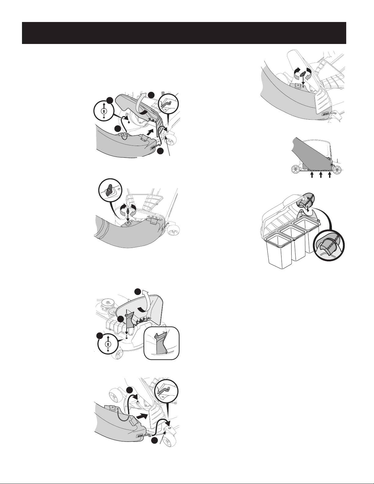
Installing the Discharge Chute & Boot
When installing the discharge chute and boot, two different installation
instructions exist. For the 54” fabricated deck units, the boot elbow mounts directly
onto the cutting deck. For the 50” and 54” stamped decks, an adapter must first be
installed. Be sure to follow the instructions that pertain to the unit you are installing
this bagger on.
54” Fabricated Deck Units:
1. Raise the deck to its
highest position.
2. Remove the deck pin
rubber protective cap, 1 in
Figure 17.
3. Raise the chute deflector
(2 in Figure 17) on the
deck and hold it while you
position the boot over the
chute opening.
4. Insert the end of the boot
elbow (3) into the hole
provided in the deck wheel
mount as shown in the
inset of Figure 17.
5. Pivot the boot rearward
until the hole in the boot
elbow aligns with the pin
on the deck. Move the boot
elbow down onto that pin
as shown in 4 of Figure 17.
6. Secure the boot elbow to
the cutting deck using a
wing knob (720-04122)
included in hardware pack 689-02364. Refer to Figure 18.
On 50” and 54” Stamped Decks:
1. Raise the deck to its
highest position.
2. Remove the deck pin
rubber protective cap, 1 in
Figure 19.
3. Raise the chute deflector (2
in Figure 19) on the deck
and hold it while you install
the chute adapter (731-
10133) (3), included in
hardware pack 689-02364,
onto the deck as shown in
Figure 19.
4. Insert the end of the boot
elbow (1) into the hole
provided in the deck wheel
mount as shown in the
inset of Figure 20.
5. Pivot the boot rearward
until the hole in the boot
elbow aligns with the pin
on the deck adapter. Move
the boot elbow down onto
that pin as shown in 2 of
Figure 20.
6. Secure the boot elbow to
the cutting deck using a
wing knob (720-04122)
included in hardware pack
689-02364. Refer to
Figure 21.
IMPORTANT! Be certain that
the bottom of the boot is
located inside of the lip of the
deck opening, as shown in
Figure 22.
7. With the bagger cover
open, insert the upper
chute tube into the boot
then pivot the upper chute tube into
position so that the chute rests in the
upper chute support. See Figure 23.
NOTE: Make sure to align the upper chute with
the ridges on the upper chute support.
8. Close the grass catcher cover.
2
4
1
3
Do Not Use This Hole!
Figure 17
Figure 18
1
3
2
Figure 19
Do Not Use This Hole!
1
2
Figure 20
Figure 21
Figure 22
Figure 23
Loading ...
Loading ...
Loading ...