
Owner's Manual
®
15.5 HP
ELECTRIC START
42" MOWER
TRANSAXLE
LAWN TRACTO
Model No.
917.270611
o Safety
®Assembly
,, Operation
, Maintenance
, Repair Parts
CAUTION:
Read and follow all
Safety Rules and Instructions
before operatingthis equip-
ment.
For answers to your questions
about this product, Call:
1-800-659-5917
Sears Craftsman Help: Line
5 am - 5 pro, Mon- Sat
Sears, Roebuck and Co., Hoffman Estates, IL 60179 ,

Warranty ................................................. 2
Safety Rules ........................................... 2
Assembly ................................................ 8
Operation .............................................. 11
Maintenance Schedule ......................... 17
Maintenance ......................................... 17
Product Specifications ............... :........... 5
Service and Adjustments.: .................... 21
Storage ...................................... ........... 27
Troubleshooting .................................... 28
Repair Parts ......................................... 32
Parts Ordering ....... ................ Back Cover
LIMITED TWO YEAR WARRANTY ON CRAFTSMAN RIDING EQUIPMENT
For two (2) years from the date of purchase, if this Craftsman Riding Equipment is main-
tained, lubricated and tuned up according to the instructions in the owner's manual,
Sears will repair or replace, free of charge, any parts found to be defective in material or
workmanship.
This Warranty does not cover:
• Expendable items which become worn during normal use, such as blades, spark
plugs, air cleaners, belts, etc.
o Tire replacement or repair caused by punctures from outside objects, such as nails,
thorns, stumps, or glass.
° Repairs necessary because of operator abuse, negligence, improper storage or acci-
dent or the failure to maintain the equipment according to the instructions contained in
the owner's manual.
o Riding equipment used for commercial or rental purposes.
LIMITED 90 DAY WARRANTY ON BATTERY
For ninety (90) days from date of purchase, if any battery included with this riding equip-
ment proves defective in material or workmanship and our testing determines the bat-
tery will not hold a charge, Sears will replace the battery at no charge. In-home warranty
service on your Craftsman riding equipment is available at no charge for 30 days from
the date of purchase. Please contact your nearest service center. After 30 days from the
date of purchase, warranty service is available by taking your Craftsman riding equip-
ment to your nearest Sears Service Center. (in-home warranty service will still be avail-
able after 30 days from the date of purchase but a standard trip charge will apply). This
warranty applies only while this product is in the United States. This Warranty gives you
specific legal rights, and you may also have other rights which may vary from state to
state.
Sears, Roebuck and Co., D/817 WA, Hoffman Estates, IL 60179
GENERAL OPERATION
° Read, understand, and follow all instruc-
tions in the manual and on the machine
before starting.
° Only allow responsible adults, who are
familiar with the instructions, to operate
the machine.
• Clear the area of objects such as rocks,
toys, wire, etc., which could be picked
up and thrown by the blade.
° Be sure the area is clear of other people
before mowing. Stop machine if anyone
enters the area.
2
o Never carrypassengers.
° Do not mow in reverse unless absolute-
ly necessary.Always look down and
behind before and while backing.
o Be aware of the mower discharge direc-
tion and do not point it at anyone. Do
not operatethe mower withouteither
the entire grass catcher or the guard in
place.
• Slow downbefore turning.
° Never leave a runningmachine unat-
tended. Always turn off blades, set park-
ing brake, stopengine, and remove
keys before dismounting.
o Turn off blades when not mowing.
o Stop engine before removing grass
catcher or unclogging chute.
o Mow only in daylight or good artificial
light.
o Do not operate the machine while under
the influence of alcohol or drugs.
o Watch for traffic when operating near or
crossing roadways.
o Use extra care when loading or unload-
ing the machine into a trailer or truck.
SLOPE OPERATION
Slopes are a major factor related to loss-
of-control and tipover accidents, which
can result in severe injury or death. All
slopes require extra caution. If you cannot
back up the slope or if you feel uneasy on
it, do not mow it.
DO:
° Mow up and down slopes, not across.
= Remove obstacles such as rocks, tree
limbs, etc.
o Watch for holes, ruts, or bumps. Uneven
terrain could overturn the machine. Tall
grass can hide obstacles.
, Use slow speed. Choose a low gear so
that you will not have to stop or shift
while on the slope.
° Follow the manufacturer's recommen-
dations for wheel weights or counter-
weights to improve stability.
° Use extra care with grass catchers or
other attachments. These can change
the stability of the machine.
° Keep all movement on the slopes slow
and gradual. Do not make sudden
changes in speed or direction.
° Avoid starting or stopping on a slope. If
tires lose traction, disengage the blades
and proceed slowly straight down the
slope.
DO NOT:
° Do notturn on slopes unless necessary,
and then, turn slowly and gradually
downhill, if possible.
° Do not mow near drop-offs, ditches, or
embankments. The mower could sud-
denly turn over if a wheel is over the
edge of arcliff or ditch, or if an edge
caves in.
° Do not mow on wet grass. Reduced
traction could cause sliding.
= Do nottry to stabilize the machine by
putting your foot on the ground.
• Do not use grass catcher on steep
slopes.
CHILDREN
Tragic accidents can occur if the operator
is not alert to the presence of children.
Children are often attracted to the
machine and the mowing activ!ty. Never
assume that children will remain where
you last saw them.
o Keep children out of the mowing area
and under the watchful care of another
responsible adult.
, Be alert and turn machine off if children
enter the area.
° Before and when backing, look behind
and down for small children.
° Never carry children. They may fall off
and be seriously injured or interfere with
safe machine operation.
• Never allow children to operate the
machine.
° Use extra care when approaching blind
corners, shrubs, trees, or other objects
that may obscure vision.
SERVICE
• Use extra care in handling gasoline and
other fuels. They are flammable and
vapors are explosive.
- Use only an approved container.
- Never remove gas cap or add fuel
with the engine running. Allow en-
gine to cool before refueling. Do not
smoke.
- Never refuel the machine indoors.
- Never store the machine or fuel
container inside where there is an
open flame, such as a water heater.
° Never run a machine inside a closed
area.
= Keep nuts and bolts, especially blade
attachment bolts, tight and keep equip-
ment in good condition.
• Never tamper with safety devices.
Check their proper operation regularly.
° Keep machine free of grass, leaves, or
other debris build-up. Clean oil or fuel
spillage. Allow machine to cool before
storing.
° Stop and inspect the equipment if you
strike an object. Repair, if necessary,
before restarting.
3
Never make adjustmentsor repairswith
the engine running.
Grass catcher componentsare subject
to wear, damage, and deterioration,
which couldexpose movingpartsor
allow objectsto be thrown. Frequently
check components and replace with
manufacturer'srecommended parts,
when necessary.
Mower blades are sharp and can cut.
Wrap the blade(s) or wear gloves, and
use extra cautionwhen servicingthem.
Check brake operationfrequently.
Adjust and service as required.
• Be sure the area is clear of other people
before mowing. Stop machine if anyone
enters the area.
° Never carry passengers.
° Do notmow in reverse unlessabsolute-
ly necessary.Always Iobk down and
behind before and while backing.
° Never carry children.They may fall off
and be seriouslyinjured or interfere with
safe machine operation.
• Keep children out of the mowing area
and under the watchful care of another
responsibleadult.
° Be alert and turn machine off if children
enter the area.
° Before and when backing, lookbehind
and downfor small children.
_Look for this symbol to point out impor-
tant safety precautions. It means CAU-
TION!t! BECOME AWARE!!! YOUR SAFE-
TY IS INVOLVED.
,_,CAUTION: In order to prevent acciden-
tal startingwhen settingup, transporting,
adjustingor making repairs always discon-
nect spark plug wire and place wire where
it cannot contactspark plug.
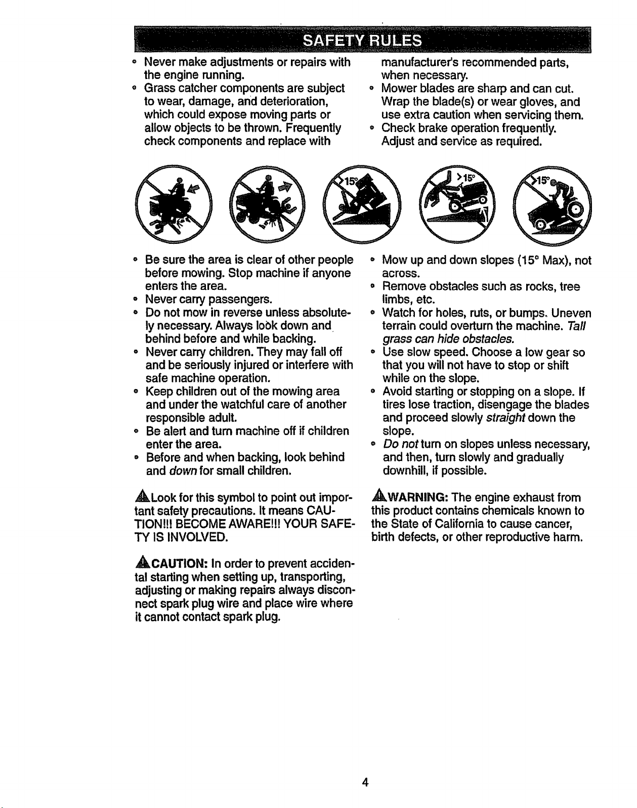
o Mow up and down slopes (15° Max), not
across.
° Remove obstaclessuch as rocks,tree
limbs, etc.
,, Watch for holes, ruts,or bumps. Uneven
terrain couldoverturnthe machine. Taft
grass can hide obstac/es.
° Use slow speed. Choose a low gear so
that you willnot have to stop or shift
while on the slope.
° Avoid startingor stoppingon a slope. If
tires lose traction,disengage the blades
and proceed slowly straight down the
slope.
o Do not turn on slopes unless necessary,
and then, turn slowlyand gradually
downhill, if possible.
,_WARNING: The engine exhaust from
this product containschemicals known to
the State of Californiato cause cancer,
birth defects, or other reproductiveharm.
4
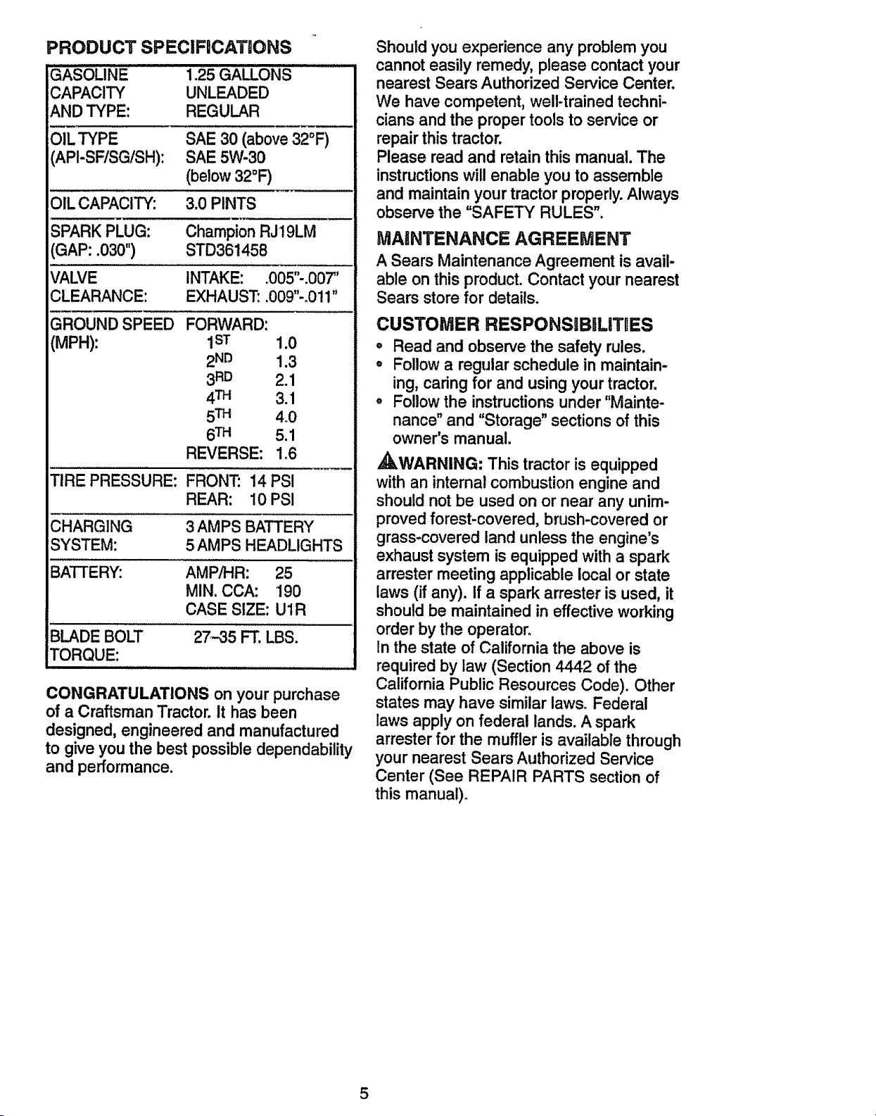
PRODUCT SPECIFiCATiONS
GASOLINE 1.25 GALLONS
CAPACITY UNLEADED
AND TYPE: REGULAR
OIL TYPE SAE 30 (above 32°F)
(API-SF/SG!SH): SAE 5W-30
(below 32°F)
OIL CAPACITY: 3.0 PINTS
SPARK PLUG: Champion RJ19LM
(GAP: .030") STD361458
VALVE INTAKE: .005"-.007"
CLEARANCE: EXHAUST: .009"-o011"
GROUND SPEED
(MPH):
FORWARD:
1sT 1.0
2ND 1.3
3RD 2.1
4TM 3.1
5TM 4.0
6TM 5.1
REVERSE: 1_6
TIRE PRESSURE: FRONT: 14 PS!
REAR: 10PSI
CHARGING 3 AMPS BATTERY
SYSTEM: 5 AMPS HEADLIGHTS
AMPiHR: 25
MIN. CCA: 190
CASE SIZE: UlR
BLADE BOLT 27-35 FT. LBS.
TORQUE:
CONGRATULATIONS on your purchase
of a Craftsman Tractor. it has been
designed, engineered and manufactured
to give you the best possible dependability
and performance.
Should you experience any problem you
cannot easily remedy, please contact your
nearest Sears Authorized Service Center.
We have competent, well-trained techni-
cians and the proper tools to service or
repair this tractor.
Please read and retain this manual. The
instructions will enable you to assemble
and maintain your tractor properly. Always
observe the "SAFETY RULES",
MAINTENANCE AGREEMENT
A Sears Maintenance Agreement is avail-
able on this product. Contact your nearest
Sears store for details.
CUSTOMER RESPONSIBILITBES
', Read and observe the safety rules.
o Follow a regular schedule in maintain-
ing, caring for and using your tractor.
° Follow the instructions under "Mainte-
nance" and "Storage" sections of this
owner's manual.
,_WARNING: This tractor is equipped
with an internal combustion engine and
should not be used on or near any unim-
proved forest-covered, brush-covered or
grass-covered land unless the engine's
exhaust system is equipped with a spark
arrester meeting applicable local or state
laws (if any). If a spark arrester is used, it
should be maintained in effective working
order by the operator.
In the state of California the above is
required by law (Section 4442 of the
California Public Resources Code). Other
states may have similar laws. Federal
laws apply on federal lands. A spark
arrester for the muffler is available through
your nearest Sears Authorized Service
Center (See REPAIR PARTS section of
this manual).
5
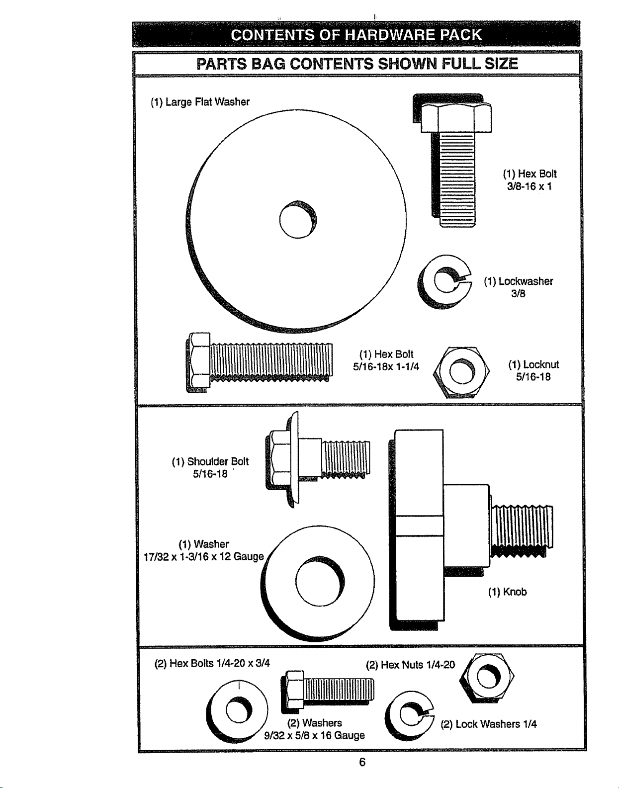
PARTS BAG CONTENTS SHOWN FULL SiZE
(1) Large Flat Washer
(1) Hex Bolt
3/8-16 x I
(1) Lockwasher
3/8
(1) Hex Bolt
5/16-18x 1-1t4 _ (1) Locknut
5/16-18
(1) Shoulder Bolt
5/16-18
(1) Washer
17/32 x 1-3/16 x 12 Gauge
(1) Knob
(2) Hex Bolts 1/4-20 x 3/4
(2) Washers
/32 x 5/8 x 16 Gauge
6
(2) Hex Nuts 1/4-20
(2) Lock Washers 1/4
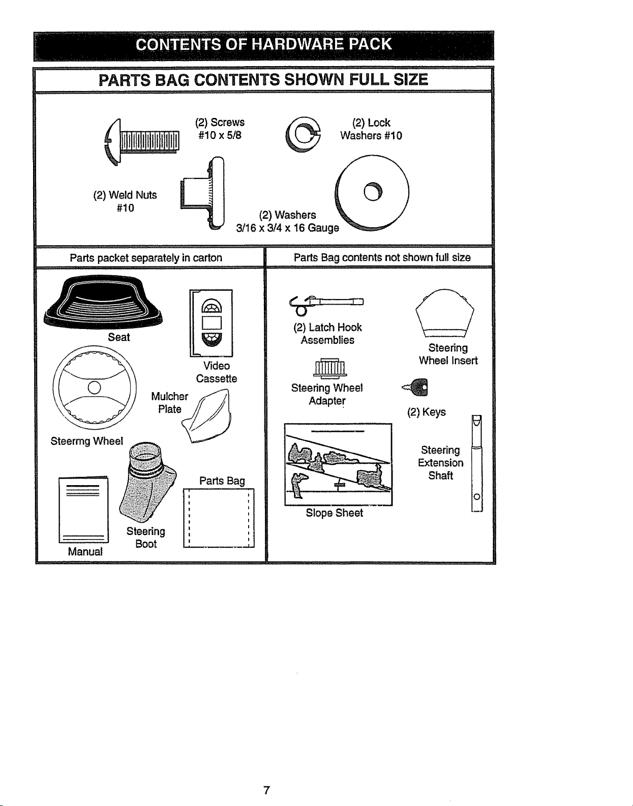
PARTS BAG CONTENTS SHOWN FULL SIZE
(2) Weld Nuts
#10
(2) Screws
#10 x 5/8
(2) Lock
Washers #10
3/16 (2)!4Wash6r_aug _
Parts packet separately in carton
Seat
Video
Cassette
Parts Bag contents not shown full size
(2) Latch Hook
Assemblies
Steering Wheel
Adapter
Slope Sheet
Steering
Wheel Insert
(2) Keys
I
Steering =
Extension
Shaft
o
7
Yournew tractor has been assembled at the factory with exception of those parts left
unassembled for shipping purposes. To ensure safe and proper operation of your tractor
all parts and hardware you assemble must be tightened securely. Use the correct tools
as necessary to insure proper tightness. Review the video cassette before you begin.
TOOLS REQUIRED FOR
ASSEMBLY
A socketwrenchset willmake assembly
easier.Standardwrenchsizesyou need
are listed below.
(1) 9/16" wrench
(2) 1/2" wrench
(1) Pliers
(1) Utility knife
(2) 7/16" wrenches
(1) Phillips Screw-
driver
(1) Tire pressure
gauge
When right or left hand is mentioned in
this manual, it means, from your point of
view,when you are in the operatingposi-
tion (seated behind the steeringwheel).
TO REMOVE TRACTOR FROM
CARTON
UNPACK CARTON
o Remove all accessible loose parts and
parts boxes from shipping carton (See
page 6).
° Cut, from top to bottom, along lines on
all four comers of shipping carton, and
lay panels flat.
o Check for any additional loose parts or
boxes and remove.
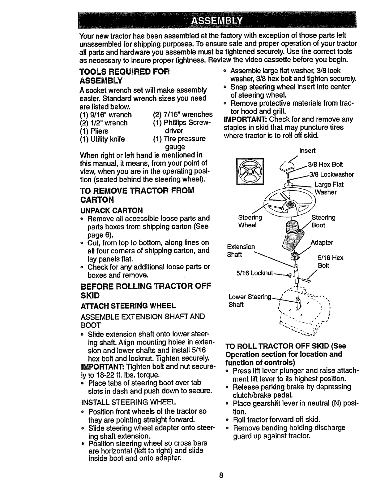
o Assemblelarge flat washer,3/8 lock
washer,3/8 hex boltand tighten securely.
o Snap steeringwheel insert into center
of steeringwheel.
° Remove protective materialsfrom trac-
tor hood and grill.
IMPORTANT: Check for and remove any
staples in skid that may puncturetires
where tractoris to roll off skid.
Insert
BEFORE ROLLING TRACTOR OFF
SKID
ATTACH STEERING WHEEL
ASSEMBLE EXTENSION SHAFT AND
BOOT
° Slide extension shaft onto lower steer-
ing shaft. Align mounting holes in exten-
sion and lower shafts and install 5/16
hex bolt and Iocknut. Tighten securely.
IMPORTANT" Tighten bolt and nut secure-
ly to 18-22 ft. lbs. torque.
• Place tabs of steering boot over tab
slots in dash and push down to secure.
INSTALL STEERING WHEEL
• Position front wheels of the tractor so
they are pointingstraightforward.
o Slide steering wheel adapter onto steer-
ing shaft extension.
° Positionsteering wheel so cross bars
are horizontal(left to right) and slide
inside boot and onto adapter.
,.<:. -/
TO ROLL TRACTOR OFF SKID (See
Operation section for location and
function of controls)
° Press liftlever plunger and raise attach-
ment lift lever to its highestposition.
° Release parking brake by depressing
clutch/brakepedal.
° Place gearshift lever in neutral (N) posi-
tion.
° Roll tractorforward off skid.
° Remove banding holding discharge
guard up against tractor.
8
HOW TO SET UP YOUR TRACTOR
CONNECT BATTERY
,_CAUTION: Do not short batter,] termi-
nals by allowinga wrench or any other
object to contact both terminalsat the
same time. Before connectingbattery, re-
move metal bracelets, wristwatchbands,
rings,etc. Positiveterminal must be con-
nected first to prevent sparking from acci-
dental grounding.
o Remove cardboard packing from seat
pan and liftseat pan to raised position.
, Open battery box door and remove pro-
tectiveplastic.
° Remove terminal protectivecaps and
discard.
• if this battery is put intoservice after
month and year indicatedon label (label
located between terminals) charge bat-
tery for minimumof one hour at 6-10
arnps.
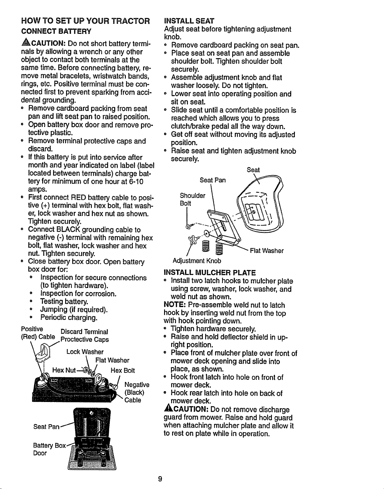
° Firstconnect RED battery cable to posi-
tive (+) terminal with hex bolt,flat wash-
er, lockwasher and hex nut as shown.
Tightensecurely.
° Connect BLACK groundingcable to
negative (-) terminal with remaininghex
bolt,flat washer, lockwasher and hex
nut.Tighten securely.
° Close battery box door. Open battery
box door for:
° Inspection for secure connections
(to tighten hardware).
° Inspection for corrosion.
° Testing battery.
° Jumping (if required).
° Periodic charging.
Positive Discard Terminal
(Red) Cable Proctective Caps
Lock Washer
Flat Washer
Hex Bolt
Negative
(Black)
Cable
Seat
Battery
Door
INSTALL SEAT
Adjust seat before tighteningadjustment
knob.
° Remove cardboard packing on seat pan.
° Place seat on seat pan and assemble
shoulder bolt.Tighten shoulder bolt
securely.
o Assemble adjustment knoband flat
washer loosely.Do not tighten.
o Lower seat into operatingpositionand
sit on seat.
o Slide seat until a comfortableposition is
reached which allows you to press
clutch/brake pedal all the way down.
° Get off seat without moving its adjusted
position.
, Raise seat and tighten adjustment knob
securely.
SeatPan
Shoulder \
Adjustment Knob
Seat
Flat Washer
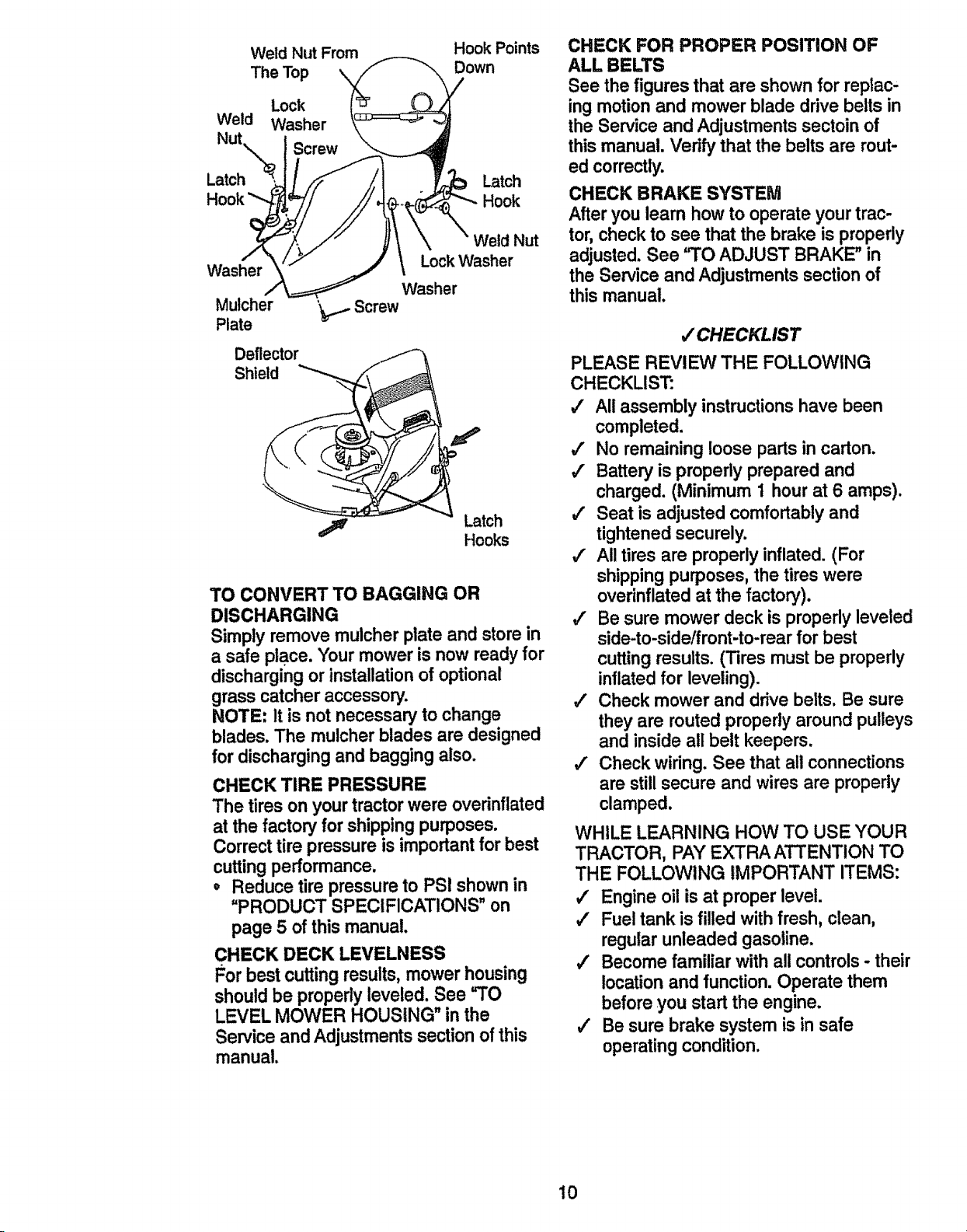
INSTALL MULCHER PLATE
, Install two latch hooks to mutcher plate
usingscrew, washer, lockwasher, and
weld nut as shown.
NOTE: Pre-assemble weld nut to latch
hook by insertingweld nut from the top
with hook pointingdown.
- Tighten hardware securely.
° Raise and hold deflectorshield in up-
right position.
° Place front of mulcher plate over front of
mower deck opening and slide into
place, as shown.
° Hook front latch into hole on front of
mower deck.
° Hook rear latch into hole on back of
ower deck.
CAUTION. Do not remove discharge
guard from mower. Raise and hold guard
when attaching mulcher plate and allow it
to rest on plate while in operation.
9
Weld Nut From Hook Points
The Top Down
Lock
Weld Washer
Nut
Latch Latch
Hook Hook
Weld Nut
LockWasher
Washer
Washer
Mulcher ',_,..,.Screw
Plate
Deflector
Shield
,_ Latch
Hooks
TO CONVERT TO BAGGING OR
DISCHARGING
Simplyremove mulcherplate and storein
a safe place. Your mower is now readyfor
dischargingor installationof optional
grass catcher accessory.
NOTE: It is not necessaryto change
blades. The mulcherblades are designed
for dischargingand bagging also.
CHECK TIRE PRESSURE
The tires on your tractor were overinflated
at the factory for shipping purposes.
Correcttire pressure is importantfor best
cuttingperformance.
,, Reduce tire pressureto PSI shownin
"PRODUCT SPECIFICATIONS" on
page 5 of this manual.
CHECK DECK LEVELNESS
For best cutting results,mower housing
shouldbe properlyleveled. See =TO
LEVEL MOWER HOUSING" in the
Service andAdjustmentssection of this
manual.
CHECK FOR PROPER POSITION OF
ALL BELTS
See the figures that are shown for replac,
ing motion and mower blade drive belts in
the Service and Adjustments sectoin of
this manual. Verify that the belts are rout-
ed correctly.
CHECK BRAKE SYSTEM
After you learn how to operate your trac-
tor,check to see that the brake is properly
adjusted. See "TO ADJUST BRAKE" in
the Service and Adjustmentssection of
this manual.
/CHECKLIST
PLEASE REVIEW THE FOLLOWING
CHECKLIST:
/ All assembly instructions have been
completed.
/ No remaining loose parts in carton.
/ Battery is properly prepared and
charged. (Minimum 1 hour at 6 amps).
#" Seat is adjusted comfortably and
tightened securely.
/ All tires are properly inflated. (For
shipping purposes, the tires were
overinflated at the factory).
/ Be sure mower deck is properly leveled
side-to-side/front-to-rear for best
cutting results. (Tires must be properly
inflated for leveling).
/ Check mower and drive belts. Be sure
they are routed properly around pulleys
and inside all belt keepers.
# Check wiring. See that all connections
are still secure and wires are properly
clamped.
WHILE LEARNING HOW TO USE YOUR
TRACTOR, PAY EXTRA ATTENTION TO
THE FOLLOMVING IMPORTANT ITEMS:
/ Engine oil is at proper level.
/ Fuel tank is filled with fresh, clean,
regular unleaded gasoline.
4 Become familiar with all controls - their
location and function. Operate them
before you start the engine.
/ Be sure brake system is in safe
operating condition.
10
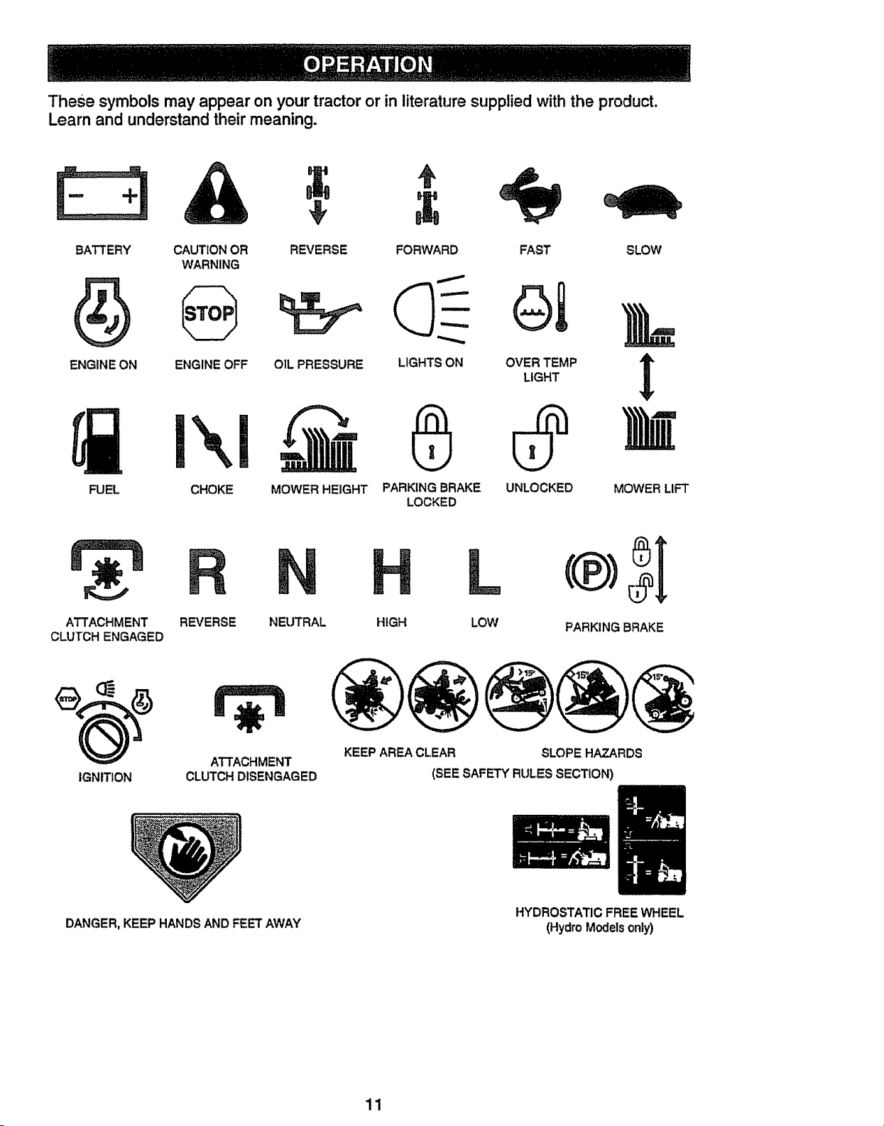
These symbols may appear on your tractor or in literature supplied with the product.
Learn and understand their meaning.
BATTERY CAUTION OR REVERSE
WARNING
ENGINE ON ENGINE OFF OIL PRESSURE
FORWARD SLOW
LIGHTS ON
FUEL CHOKE MOWER HEIGHT PARKING BRAKE
LOCKED
FAST
OVER TEMP
LIGHT
UNLOCKED
MOWER LIFT
ATTACHMENT
CLUTCH ENGAGED
REVERSE NEUTRAL
HIGH
L
LOW PARKING BRAKE
IGNITION
ATTACHMENT
CLUTCH DISENGAGED
KEEP AREA CLEAR SLOPE HAZARDS
(SEE SAFETY RULES SECTION)
DANGER, KEEP HANDS AND FEET AWAY
HYDROSTATIC FREE WHEEL
(Hydro Models only)
11
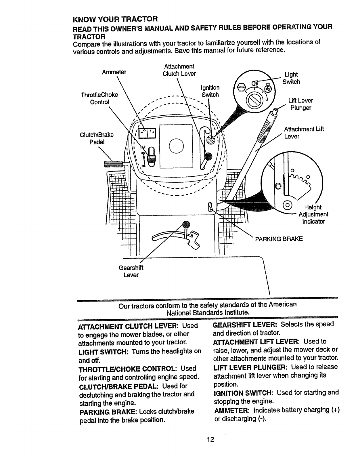
KNOW YOUR TRACTOR
READ THIS OWNER'S MANUAL AND SAFETY RULES BEFORE OPERATING YOUR
TRACTOR
Compare the illustrations with your tractor to familiarize yourself with the locations of
various controls and adjustments. Save this manual for future reference.
Attachment
Ammeter Clutch Lever
ThrottteChoke
Control
Light
Switch
Ignition
. _ .... Switch
.," Lift Lever
•' " Plunger
t
ClutcWBrake
Pedal
©
Attachment Lift
Lever
o
Height
Adjustment
tndicator
PARKING BRAKE
GearshiftLever _'\!/
Our tractors conformto the safety standards of the Amedcan
National Standards Institute.
ATTACHMENT CLUTCH LEVER: Used GEARSHIFT LEVER= Selects the speed
to engage the mower blades, or other and directionof tractor.
attachments mounted to your tractor. ATTACHMENT LIFT LEVER: Used to
LIGHT SWITCH: Turns the headlightson raise, lower, and adjustthe mower deck or
and off. other attachmentsmounted to your tractor.
THROTTLE/CHOKE CONTROL: Used LIFT LEVER PLUNGER: Used to release
for starting and controllingengine speed, attachment lift lever when changingits
CLUTCH/BRAKE PEDAL: Used for position.
declutchingand braking the tractorand IGNITION SWITCH: Used for startingand
startingthe engine, stopping the engine.
PARKING BRAKE: Locksclutch/brake AMMETER: Indicatesbattery charging (+)
pedal intothe brake position, oi"discharging(-).
12
The operation of any tractor can result in foreign objects thrown into the
eyes, which can result in severe eye damage. Always wear safety glass-
es or eye shields while operating your tractor or performing any adjust-
ments or repairs. We recommend a wide vision safety mask over the
spectacles, or standard safety glasses.
HOW TO USE YOUR TRACTOR
Your tractor is equipped with an operator
presence sensing switch. When engine
is running, any attempt by the operator to
leave the seat without first setting the
parking brake will shut off the engine.
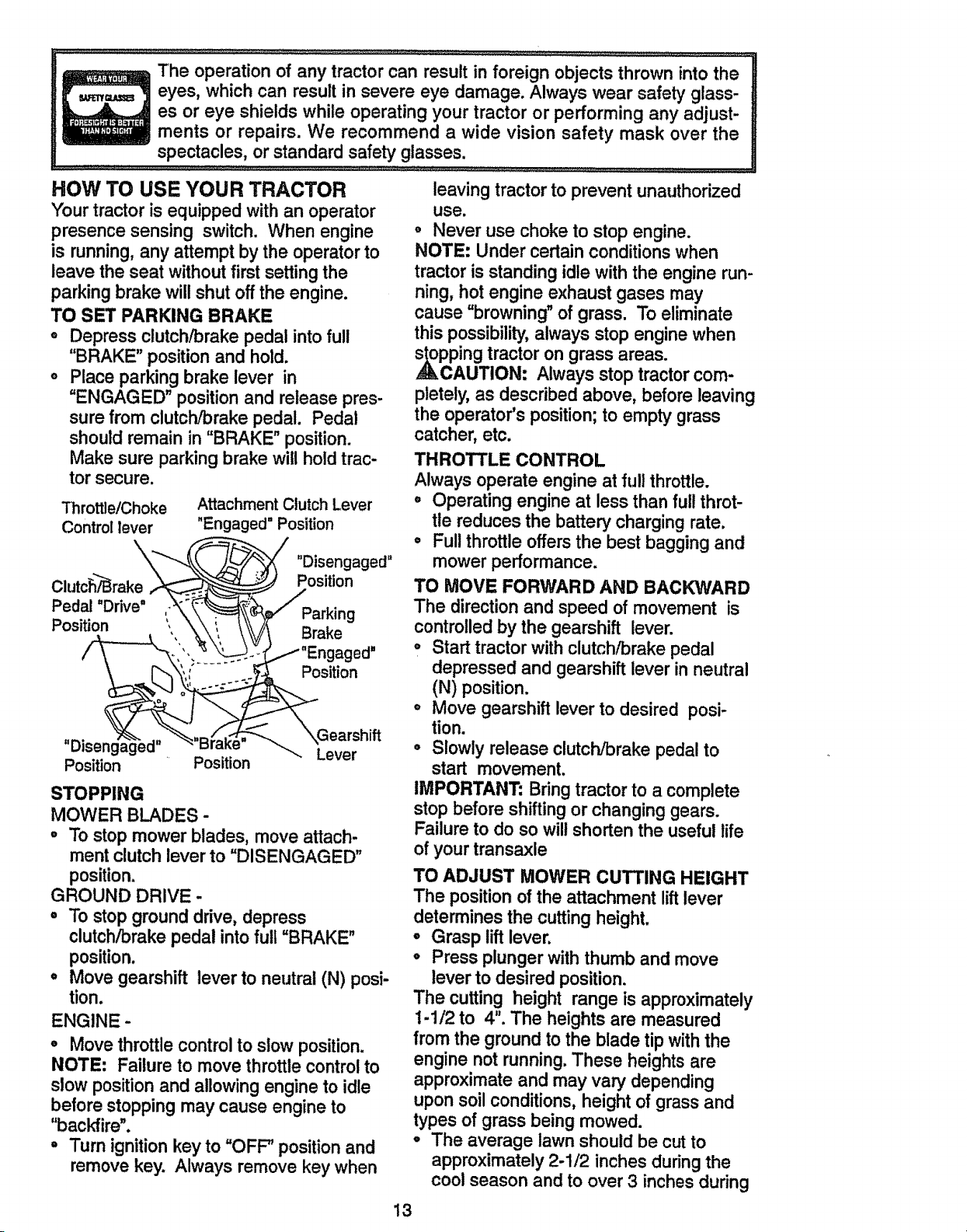
TO SET PARKING BRAKE
o Depress clutch/brake pedal into full
"BRAKE" position and hold.
o Place parking brake lever in
"ENGAGED" position and release pres-
sure from clutch/brake pedal. Pedal
should remain in "BRAKE" position,
Make sure parking brake will hold trac-
tor secure.
Throttle/Choke Attachment Clutch Lever
Control lever "Engaged" Position
"-._"_ _ "Disengaged"
ClutcS'_rake .,__._ _ Position
Pedal"Drive" ,_-" _ _/" Parkin
Position- ', "\:'\ _ r,_ irake g
/_----_:, ,_'_ _" "_Ensigtagned"
,, _ .. "%<.,_./_,.__"-_. "..Gearshift
DJsengageo" - D_u _. Lever
Position Position
STOPPING
MOWER BLADES -
° To stop mower blades, move attach.
ment clutch leverto "DISENGAGED"
position.
GROUND DRIVE -
° To stopground drive, depress
clutch/brakepedal into full "BRAKE"
position.
,, Move gearshift lever to neutral(N) posi-
tion.
ENGINE -
,, Move throttlecontrolto slow position.
NOTE: Failure to move throttlecontrolto
slow positionand allowingengine to idle
before stoppingmay cause engine to
"backfire".
= Turn ignition key to "OFF" position and
remove key. Always remove key when
leaving tractor to prevent unauthorized
use.
° Never use choke to stop engine.
NOTE; Under certain conditions when
tractor is standing idle with the engine run-
ning, hot engine exhaust gases may
cause "browning" of grass. To eliminate
this possibility, always stop engine when
pping tractor on grass areas.
CAUTION; Always stop tractor com-
pletely, as described above, before leaving
the operator's position; to empty grass
catcher, etc.
THROTTLE CONTROL
Always operate engine at full throttle.
, Operating engine at less than full throt-
tle reduces the battery charging rate.
° Full throttle offers the best bagging and
mower performance.
TO MOVE FORWARD AND BACKWARD
The direction and speed of movement is
controlled by the gearshift lever.
° Start tractor with clutch/brake pedal
depressed and gearshift lever in neutral
(N) position.
° Move gearshift lever to desired posi-
tion.
° Slowly release clutcl-dbrake pedal to
start movement.
IMPORTANT; Bring tractor to a complete
stop before shifting or changing gears.
Failure to do so will shorten the useful life
of your transaxle
TO ADJUST MOWER CUTTING HEIGHT
The positionof the attachment liftlever
determines the cutting heighL
° Grasp lift lever.
° Press plunger with thumb and move
lever to desired position.
The cutting height range is approximately
I-1/2 to 4". The heightsare measured
from the ground to the blade tip withthe
engine not running.These heightsare
approximate and may vary depending
upon soilconditions,height of grass and
types of grass being mowed.
° The average lawn should be cut to
approximately 2-1/2 inchesduringthe
cool season and to over 3 inches during
13
hot months. For healthier and better
looking lawns, mow often and after
moderate growth.
o For best cutting performance, grass
over 6 inches in height should be
mowed twice. Make the first cut relative-
ly high; the second to desired height.
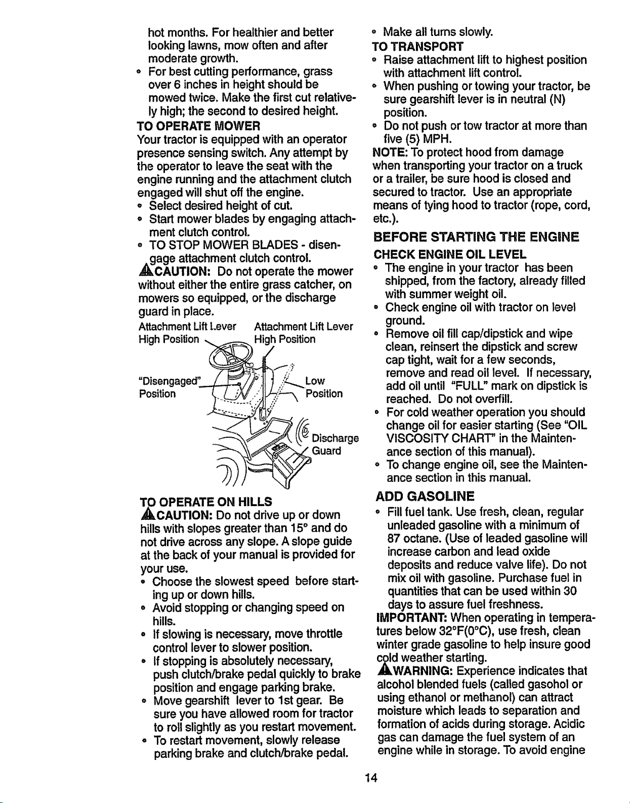
TO OPERATE MOWER
Your tractor is equipped with an operator
presence sensing switch. Any attempt by
the operator to leave the seat with the
engine running and the attachment clutch
engaged will shut off the engine.
o Select desired height of cut.
• Start mower blades by engaging attach-
ment clutch control.
o TO STOP MOWER BLADES - disen-
,_cage attachment clutch control.
AUTION: Do not operate the mower
without eitherthe entire grass catcher, on
mowers so equipped, or the discharge
guard in place.
Attachment Lift Lever Attachment Lift Lever
High Position _. High Position
=Disengaged"position___ LOWposition
_ OPERATE ON HILLS
CAUTION: Do not drive up or down
hillswith slopesgreater than 15° and do
not drive across any slope. A slope guide
at the back of your manual is provided for
your use.
• Choose the slowestspeed before start-
ing up or down hills.
o Avoid stoppingor changingspeed on
hills.
o If slowing is necessary, move throttle
controllever to slower position.
° If stoppingis absolutely necessary,
push clutch/brakepedal quickly to brake
positionand engage parkingbrake.
• Move gearshift lever to 1st gear. Be
sure you have allowed room for tractor
to rollslightly as you restart movement.
° To restart movement, slowly release
parkingbrake and clutch/brakepedal.
o Make all turns slowly.
TO TRANSPORT
o Raise attachment lift to highest position
with attachment lift control.
o When pushing or towing your tractor, be
sure gearshift lever is in neutral (N)
position.
Do not push or tow tractor at more than
five (5) MPH.
NOTE: To protect hood from damage
when transporting your tractor on a truck
or a trailer, be sure hood is closed and
secured to tractor. Use an appropriate
means of tying hood to tractor (rope, cord,
etc.).
BEFORE STARTING THE ENGINE
CHECK ENGINE OIL LEVEL
o The engine in yourtractor has been
shipped,from the factory, already filled
with summerweight oil.
° Check engine oilwith tractor on level
ground.
• Remove oil fill cap/dipstickand wipe
clean, reinsertthe dipstickand screw
cap tight,wait for a few seconds,
remove and read oil level. If necessary,
add oil until "FULL" mark on dipstickis
reached. Do not overfill.
o For cold weather operationyou should
change oil for easier starting (See "OIL
VISCOSITY' CHART" in the Mainten-
ance section of this manual).
o To change engine oil, see the Mainten-
ance sectionin this manual.
ADD GASOLINE
o Fillfuel tank. Use fresh, clean, regular
unleaded gasoline with a minimumof
87 octane. (Use of leaded gasolinewill
increase carbon and lead oxide
depositsand reduce valve life). Do not
mix oilwith gasoline. Purchase fuel in
quantitiesthat can be used within30
days to assure fuel freshness.
IMPORTANT: When operating intempera-
tures below 32°F(0°C), use fresh, clean
winter grade gasoline to help insure good
dAweatherstarting.
RNING: Experience indicatesthat
alcohol blended fuels (called gasoholor
using ethanol or methanol) can attract
moisture which leads to separation and
formation of acids during storage.Acidic
gas can damage the fuel system of an
engine while in storage.To avoid engine
t4
problems, the fuel system should be emp-
tied before storage of 30 days or longer.
Drain the gas tank, start the engine and let
it run until the fuel lines and carburetor are
empty. Use fresh fuel next season. See
Storage Instructions for additional informa-
tion. Never use engine or carburetor
cleaner products in the fuel tank or perma-
nct amage may occur.
AUTION: Fill to bottom of gas tank
filler neck. Do not overfill. Wipe off any
spilled oil or fuel. Do not store, spill or use
gasoline near an open flame.
TO START ENGINE
When starting the engine for the first time
or if the engine has run out of fuel, it will
take extra cranking time to move fuel from
the tank to the engine,
° Sit on seat in operating position,
depress clutch/brake pedal and set
parking brake.
o Place gear shift lever in neutral (N) posi-
tion.
• Move attachment clutch to "DISEN-
GAGED _ position.
° Move throttle control to choke position.
NOTE: Before starting, read the warm
and cold starting procedures below.
° Insert key into ignition and turn key
clockwise to "START" position and
release key as soon as engine starts.
Do not run starter continuously for more
than fifteen seconds per minute, if the
engine does not start after several
attempts, move throttle control to fast
position, wait a few minutes and try
again. If engine still does not start,
move the throttle control back to the
choke position and retry.
WARM WEATHER STARTING (50 ° F and
above)
° When engine starts, move the throttle
control to the fast position.
° The attachments and ground drive can
now be used. If the engine does not
accept the load, restart the engine and
allow it to warm up for one minute using
the choke as described above.
COLD WEATHER STARTING ( 50 ° F AND
BELOV_
° When engine starts, allow engine to run
with the throttle control in the choke
position until the engine runs roughly,
then move throttle control to fast posi-
tion. This may require an engine warm-
up period from several seconds to sev-
eral minutes, depending on the temper-
ature.
o The attachments can also be used dur-
ing the engine warm.up period.
NOTE: if at a high altitude (above 3000
feet) or in cold temperatures (below 32 F)
the carburetor fuel mixture may need to be
adjusted for best engine performance.
See 'q'O ADJUST CARBURETOR" in the
Service and Adjustments section of this
manual.
NOTE: At a high altitude (above 3000
feet) or in cold temperatures (below 32 F)
the carburetor fuel mixture may need to be
adjusted for best engine performance.
See 'q'O ADJUST CARBURETOR" in the
Service and Adjustments section of this
manual.
MOWING TiPS
° Tire chains cannot be used when the
mower housing is attached to tractor.
° Mower should be properly leveled for
best mowing performance. See "TO
LEVEL MOWER HOUSING" in the
Service and Adjustments section of this
manual.
° The left hand side of mower should be
used for trimming.
° Drive so that clippings are discharged
onto the area that has been cut. Have
the cut area to the right of the machine.
This will result in a more even distribu-
tion of clippings and more uniform cut-
ting.
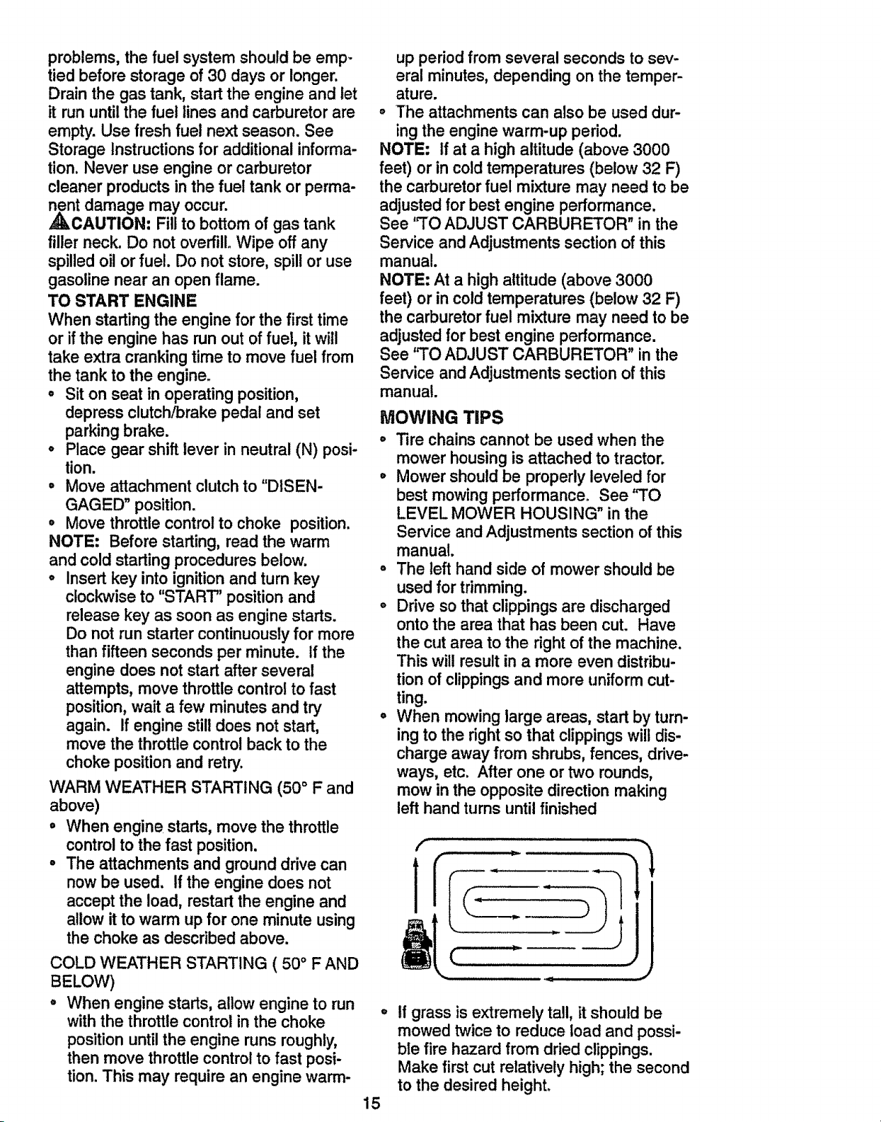
o When mowing large areas, start by turn-
ing to the right so that clippings will dis-
charge away from shrubs, fences, drive-
ways, etc. After one or two rounds,
mow in the opposite direction making
left hand turns until finished
f
1
t
, JJ
iid H iJ
15
If grass is extremely tall, it should be
mowed twice to reduce toad and possi-
ble fire hazard from dried clippings.
Make first cut relatively high; the second
to the desired height.
o Do not mow grass when it is wet. Wet
grass will plug mower and leave unde-
sirable clumps. Allow grass to dry
before mowing.
o Always operate engine at full throttle
when mowing to assure better mowing
performance and properdischarge of
material. Regulate groundspeed by se-
lectinga low enough gear to give the
mower the best cuttingperformance as
well as the quality of cut desired.
• When operating attachments,select a
groundspeed that willsuit the terrain
and give best performanceof the at-
tachment being used.
MULCHING MOWING TIPS
IMPORTANT: For best performance,
keep mower housingfree of built-upgrass
and trash. Clean after each use.
° The special mulchingblade will recut
the grass clippingsmany times and
reduce them in size so that as they fall
ontothe lawn they will disperse intothe
grass and not be noticed. Also, the
mulched grass will biodegradequickly
to providenutrientsfor the lawn.
Always mulch with yourhighestengine
(blade) speed as thiswill provide the
best recuttingactionof the blades.
o Avoid cuttingyour lawn when it is wet.
Wet grass tends to form clumpsand
interfereswiththe mulchingaction. The
best time to mow your lawn is the early
afternoon. At this time the grass has
dried and the newly cut area will not be
exposed to the directsun.
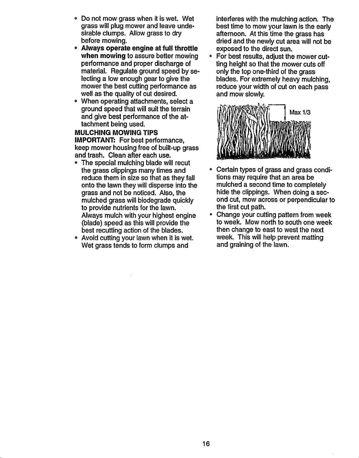
For best results,adjustthe mower cut-
ting heightso that the mower cuts off
only the top one-thirdof the grass
blades. For extremely heavy mulching,
reduce your width of cut on each pass
and mow slowly.
Max 1/3
° Certain types of grass and grass condi-
tions may requirethat an area be
mulched a secondtime to completely
hide the clippings. When doinga sec-
ond cut, mow across or perpendicularto
the first cut path.
° Change your cuttingpattern from week
to week. Mow northto southone week
then change to east to west the next
week. This will help prevent matting
and grainingof the lawn.
16
CUSTOMER RESPONSOBILmES
....... MAINTENANCE SCHEDULE .___o_y
AS YOU COMPLETE .,_"_/_._,,_O_'_
....RrEGU .SE.V,C / "rSERV,CE DATES
Check Brake Operation If V _' ....................
Check Tire Pressure _
....check Operator Presence and ..............................
T Interlock Systems
R Check for Loose Fasteners tf Q/_'7 _ .......
Sha e 'RoplaooMowe,BiaSes ....
F_ Check Battery Level
Ciean Battery and Term|nalslRechargei
Adjust Blade Bett(s) Tension
Adjust Motion Drive Belt(s) Tension
Check Engine Oil Level
Change Engine 0tl
E Clean Air Filter
_ _ _ Iw .... :.......................
rr,rr,..... ;;.............
J=
N Clean Air Screen _/'2
(_ Inspect Muffler/Spark Attester _ _.2
Replace 011 Filter (if equipped)
NE Clean ,Eng,fneCoolfng Fins ..... !f_=.
Replace Spark Plug V _' _'
Replace 'Air Filter Paper Cartridge 1_2
Replace Fue! Filler fi
1 - Change more oft,an when opomling under a heavy toad or fr_ hlgh ambient temporatural, 5 - II equipped wi_h adJust,_bla rejoice,
2 * Service more often when operating In dirty or dusty candll_orts, 6 - Not Toqulred tf equipped w|th maintenance-free baltery.
3 + If equipped wl_ oil flltar_ change oil every SO hour_ 7 - llghton front axle phtot boll to 35 _-I1_a_maxlmurn_
GENERAL RECOMMENDATIONS
The warranty on this tractor does not cover
items that have been subjected to operator
abuse or negligence. To receive full value
from the warranty, operator must maintain
tractor as instructed in this manual. Some
adjustments will need to be made periodi-
cally to properly maintain your tractor.
All adjustments in the Service and
Adjustments section of this manual should
be checked at least once each season.
- Once a year you should replace the
spark plug, clean or replace air filter, and
check blades and belts for wear. A new
spark plug and clean air filter assure
proper air-fuel mixture and help your
engine run better and last longer.
BEFORE EACH USE
° Check engine oil level.
o Check brake operation.
o Check tire pressure.
- Check operator presence and interlock
systems for proper operation.
° Check for loose fasteners.
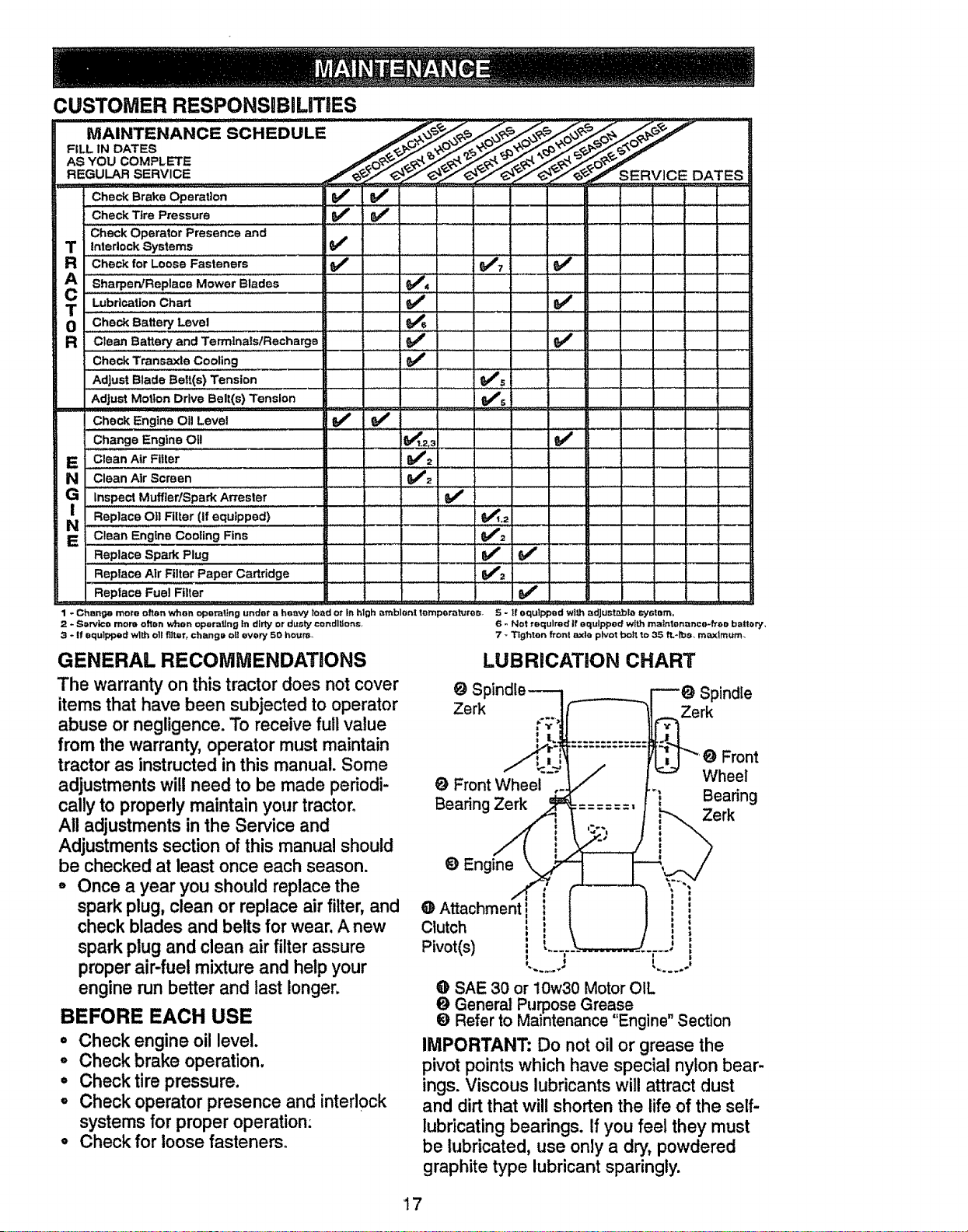
LUBRICATION CHART
O Sf Spindle
Zerk Zerk
Front
O Front Wheel Wheel
Bearing Zerk Bearing
Zerk
_t Engine
@ Attachment
Clutch
Pivot(s)
i
I l...... J
@ SAE 30 or 10w30 Motor OIL
(it General Purpose Grease
Refer to Maintenance "Engine" Section
IMPORTANT: Do not oil or grease the
pivot points which have special nylon bear-
ings. Viscous lubricants will attract dust
and dirt that will shorten the life of the self-
lubricating bearings. If you feel they must
be lubricated, use only a dry, powdered
graphite type lubricant sparingly.
17
TRACTOR
Always observe safety rules when per-
forming any maintenance.
BRAKE OPERATION
If tractor requires more than six (6) feet
stopping distance at high speed in highest
gear, then brake must be adjusted. (See
"TO ADJUST BRAKE" inthe Service and
Adjustments section of this manual).
TIRES
o Maintain proper air pressure in all tires
(See "PRODUCT SPECIFICATIONS"
on page 5 of this manual).
,, Keep tires free of gasoline, oil, or insect
control chemicals which can harm rub-
ber.
, Avoid stumps, stones, deep ruts, sharp
objects and other hazards that may
cause tire damage.
NOTE: To seal tire punctures and prevent
flat tires due to slow leaks, tire sealant
may be purchased from your local parts
dealer. Tire sealant also prevents tire dry
rot and corrosion.
BLADE CARE
For best results mower blades must be
kept sharp. Replace bent or damaged
blades.
BLADE REMOVAL
= Raise mower to highest position to allow
access to blades.
o Remove hex bolt, lock washer and flat
washer securing blade.
,, Install new or resharpened blade with
trailing edge up towards deck as shown.
• Reassemble hex bolt, lock washer and
flat washer in exact order as shown.
• Tighten bolt securely (27-35 Ft. Lbs.
torque).
IMPORTANT: Blade bolt is Grade 8 heat
treated.
Assembly
Rat Was Trailing
Edge Up
Lock Washer__ _
Hex Bolt (Grade
*A Grade 8 heat treated bolt can be
identified by six lines on the bolt head.
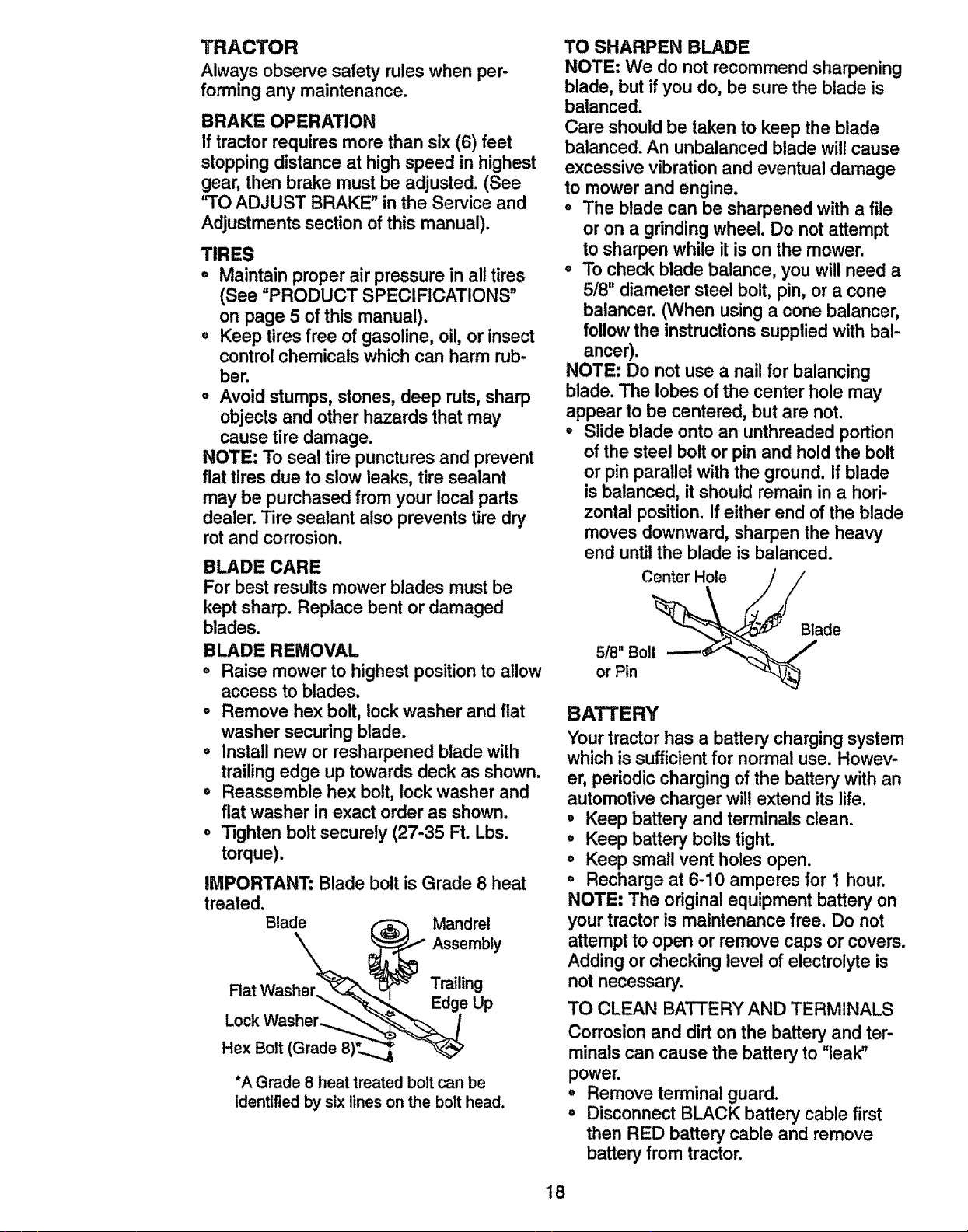
TO SHARPEN BLADE
NOTE: We do not recommend sharpening
blade, but if you do, be sure the blade is
balanced.
Care shouldbe taken to keep the blade
balanced.An unbalanced blade will cause
excessivevibration and eventual damage
to mower and engine.
o The blade can be sharpened with a file
or on a grindingwheel. Do not attempt
to sharpen while it is on the mower.
o To check blade balance, you will need a
5/8" diameter steel bolt, pin, or a cone
balancer. (When using a cone balancer,
follow the instructionssuppliedwith bal-
ancer).
NOTE: Do not use a nail for balancing
blade. The lobes of the center hole may
appear to be centered, but are not.
° Slide blade onto an unthreaded portion
of the steel bolt or pin and holdthe bolt
or pin parallel withthe ground. If blade
is balanced, it should remain in a hori-
zontal position.If either end of the blade
moves downward, sharpen the heavy
end untilthe blade is balanced.
Center Hole
5/8" Bolt
or Pin
Blade
BATTERY
Yourtractor has a battery charging system
which is sufficient for normal use. Howev-
er, periodic charging of the battery with an
automotive charger will extend its life.
° Keep battery and terminalsclean.
° Keep battery bolts tight.
• Keep small vent holes open.
,, Recharge at 6-10 amperes for 1 hour.
NOTE: The original equipmentbatteryon
yourtractoris maintenance free. Do not
attemptto open or remove caps or covers.
Addingor checking level of electrolyteis
not necessary.
TO CLEAN BATTERY AND TERMINALS
Corrosion and dirt on the battery and ter-
minals can cause the battery to "leak"
power.
o Remove terminal guard.
= Disconnect BLACK battery cable first
then RED battery cable and remove
battery from tractor.
18
• Rinse the battery with plain water and
dry.
o Clean terminals and battery cable ends
with wire brush until bright.
,, Coat terminals with grease or petroleum
jelly.
o Reinstall battery (See "CONNECT BAT-
TERY" in the Assembly section of this
manual).
Check V-belts for deterioration and wear
after 100 hours of operation and replace if
necessary. The belts are not adjustable.
Replace belts if they begin to slip from
wear.
TRANSAXLE COOLING
Keep transaxle free from build-up of dirt
and chaff which can restrict cooling.
ENGINE
LUBRICATION
Only use high quality detergent oil rated
with AP1 service classification SF, SG or
SH. Select the oil's SAE viscosity grade
according to your expected operating tem-
perature.
SAE VISCOSITY GFIADES
•F-'_--'::'-,_" o" _ =- _" _. "''_,'" I_
TEMPERATURE RANGE ANTICIPATED BEFORE NEXT OiL cHANGE
NOTE: Although multi-viscosity oils
(5W30, 10W30 etc.) improve starting in
cold weather, these multi-viscosity oils will
result in increased oil consumption when
used above 32°R Check your engine oil
level more frequently to avoid possible
engine damage from running low on oil.
Change the oil after every 25 hours of
operation or at least once a year if the
tractor is not used for 25 hours in one
year.
Check the crankcase oil level before start-
ing the engine and after each eight (8)
hours of operation. Tighten oil fill cap/dip-
stick securely each time you check the oil
level.
TO CHANGE ENGINE OIL
Determine temperature range expected
before oil change. All oil must meet AP!
service classificationSF, SG or SH.
• Be sure tractor is on level surface.
° Oil will drain more freely when warm.
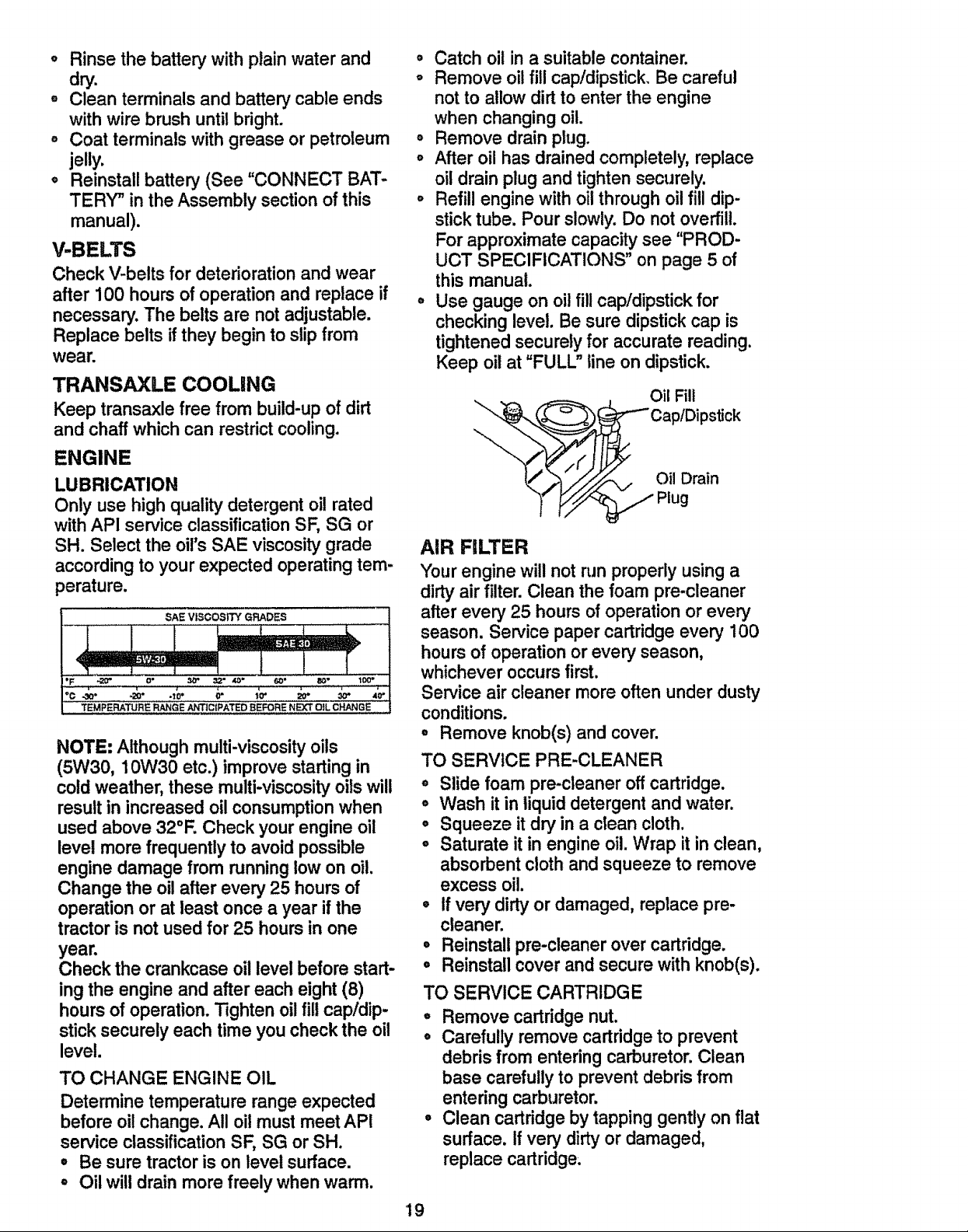
o Catch oil in a suitable container.
o Remove oil fill cap/dipstick. Be careful
not to allow dirt to enter the engine
when changing oil.
° Remove drain plug.
° After oil has drained completely, replace
oil drain plug and tighten securely.
° Refill engine with oil through oil fill dip-
stick tube. Pour slowly. Do not overfill.
For approximate capacity see "PROD-
UCT SPECIFICATIONS" on page 5 of
this manual.
° Use gauge on oil fill cap/dipstick for
checking level. Be sure dipstick cap is
tightened securely for accurate reading.
Keep oil at "FULL" line on dipstick.
19
Oil Fill
/_Cap/Dipstick
Oil Drain
Plug
AIR FILTER
Your engine will not run properly using a
dirty air filter. Clean the foam pre-cleaner
after every 25 hours of operation or every
season. Service paper cartridge every 100
hours of operation or every season,
whichever occurs first.
Service air cleaner more often under dusty
conditions.
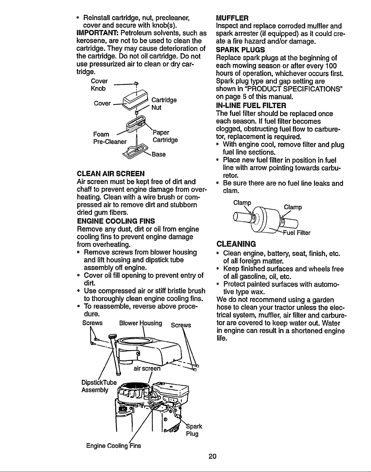
° Remove knob(s) and cover.
TO SERVICE CARTRIDGE
• Remove cartridge nut.
° Carefully remove cartridge to prevent
debris from entering carburetor. Clean
base carefully to prevent debris from
entering carburetor.
° Clean cartridge by tapping gently on flat
surface. If very dirty or damaged,
replace cartridge;
TO SERVICE PRE-CLEANER
o Slide foam pre-cleaner off cartridge.
• Wash it in liquid detergent and water.
o Squeeze it dry in a clean cloth.
° Saturate it in engine oil. Wrap it in clean,
absorbent cloth and squeeze to remove
excess oil.
° tf very dirty or damaged, replace pre-
cleaner,
° Reinstall pre-cleaner over cartridge.
o Reinstall cover and secure with knob(s).
o Reinstall cartridge, nut, precleaner,
cover and secure with knob(s).
IMPORTANT: Petroleum solvents, such as
kerosene, are not to be used to clean the
cartridge.They may cause deteriorationof
the cartridge. Do not oilcartridge. Do not
use pressurizedair to clean or dry car-
tridge.
Cover
Knob
Cover
Foam
Pre-Cleaner
_ Carkidge
Nut
'_Paper
Cartridge
CLEAN AIR SCREEN
Air screen mustbe kept free of dirt and
chaffto preventengine damage from over-
heating. Clean with a wire brush or com-
pressed air to remove dirtand stubborn
driedgum fibers.
ENGINE COOLING FINS
Remove any dust, dirt or oil from engine
coolingfins to preventengine damage
from overheating.
• Remove screws from blower housing
and lift housingand dipsticktube
assembly off engine.
° Cover oilfill openingto prevent entry of
dirt.
° Use compressed air or stiffbristlebrush
to thoroughlyclean engine coolingfins.
° To reassemble, reverse above proce-
dure.
Screws Blower Housing
MUFFLER
Inspect and replace corroded muffler and
spark arrester (if equipped) as it could cre-
ate a fire hazard and/or damage.
SPARK PLUGS
Replace spark plugs at the beginningof
each mowing season or after every 100
hours of operation,whichever occursfirst.
Spark plug type and gap setting are
shownin "PRODUCT SPECIFICATIONS"
on page 5 of this manual.
IN-LINE FUEL FILTER
The fuel filter shouldbe replaced once
each season. If fuel filter becomes
clogged, obstructingfuel flow to carbure-
tor,replacement is required.
o With engine cool, remove filter and plug
fuel linesections.
° Place new fuel filter in position in fuel
linewith arrowpointingtowards carbu-
retor.
° Be sure there are no fuel line leaks and
clam.
CLEANING
o Clean engine, battery, seat, finish, etc.
of all foreign matter.
o Keep finished surfaces and wheels free
of all gasoline,oil, etc.
• Protectpainted surfaces with automo-
tive type wax.
We do not recommend using a garden
hose to clean your tractor unlessthe elec-
tricalsystem, muffler, air filter and carbure-
tor are covered to keep water out. Water
in engine can resultin a shortened engine
life.
air screen
Assembly
Engine Cooling
Plug
2O
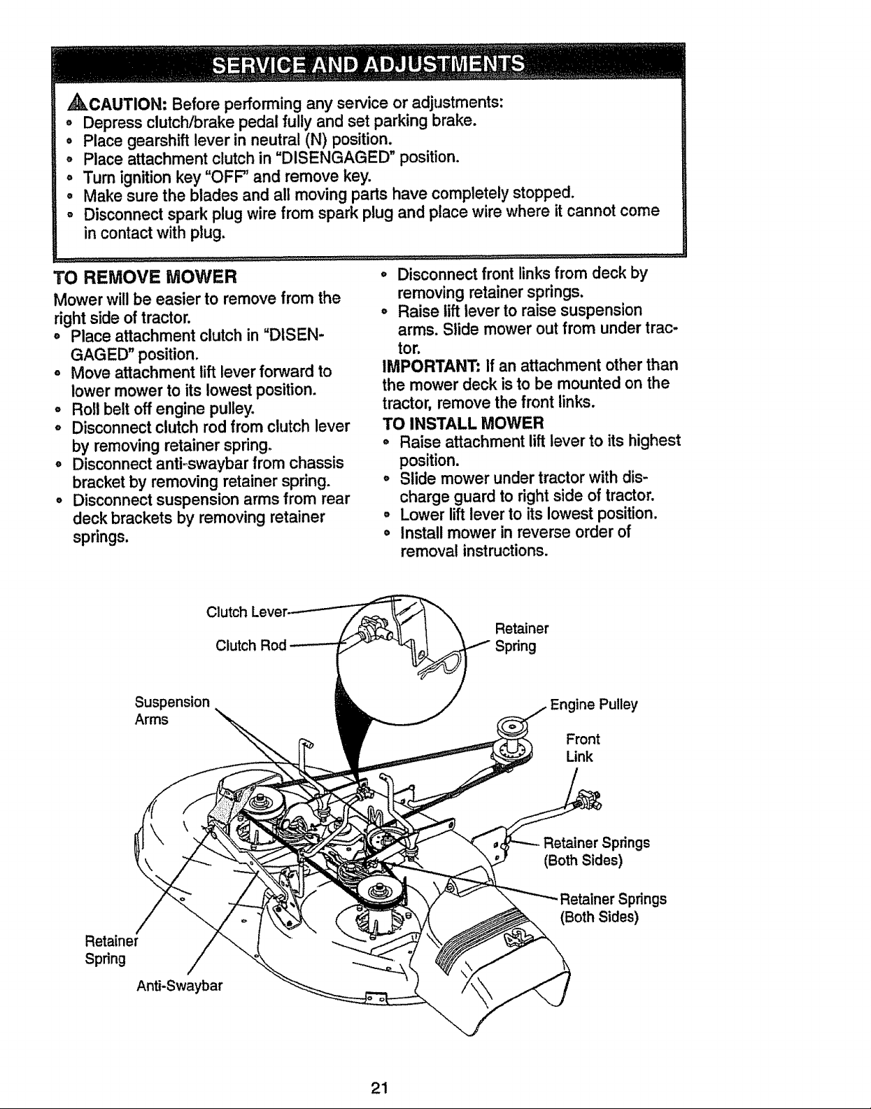
,_kCAUTION: Before performing any service or adjustments:
o Depress clutct-gbrake pedal fully and set parking brake
, Place gearshift lever in neutral (N) position.
• Place attachment clutch in "DISENGAGED" position
o Turn ignition key "OFF' and remove key
° Make sure the blades and all moving parts have completely stopped.
o Disconnect spark plug wire from spark plug and place wire where it cannot come
in contact with plug
TO REMOVE MOWER
Mower will be easier to remove from the
right side of tractor
o Place attachment clutch in "DISEN-
GAGED" position
° Move attachment lift lever forward to
lower mower to its lowest position
o Roll belt off engine pulley.
o Disconnect clutch rod from clutch lever
by removing retainer spring
° Disconnect antFswaybar from chassis
bracket by removing retainer spring
o Disconnect suspension arms from rear
deck brackets by removing retainer
springs
° Disconnect front links from deck by
removing retainer springs.
° Raise lift lever to raise suspension
arms Slide mower out from under trac-
tor
IMPORTANT: If an attachment other than
the mower deck is to be mounted on the
tractor, remove the front links
TO INSTALL MOWER
o Raise attachment lift lever to its highest
position.
o Slide mower under tractor with dis-
charge guard to right side of tractor,
o Lower lift lever to its lowest position.
o Install mower in reverse order of
removal instructions.
Clutch
Clutch
Retainer
Spring
Suspension
Arms
ine Pulley
Front
Link
Retainer
Spring
Anti-Swaybar
Retainer Springs
(Both Sides)
Springs
(Both Sides)
21
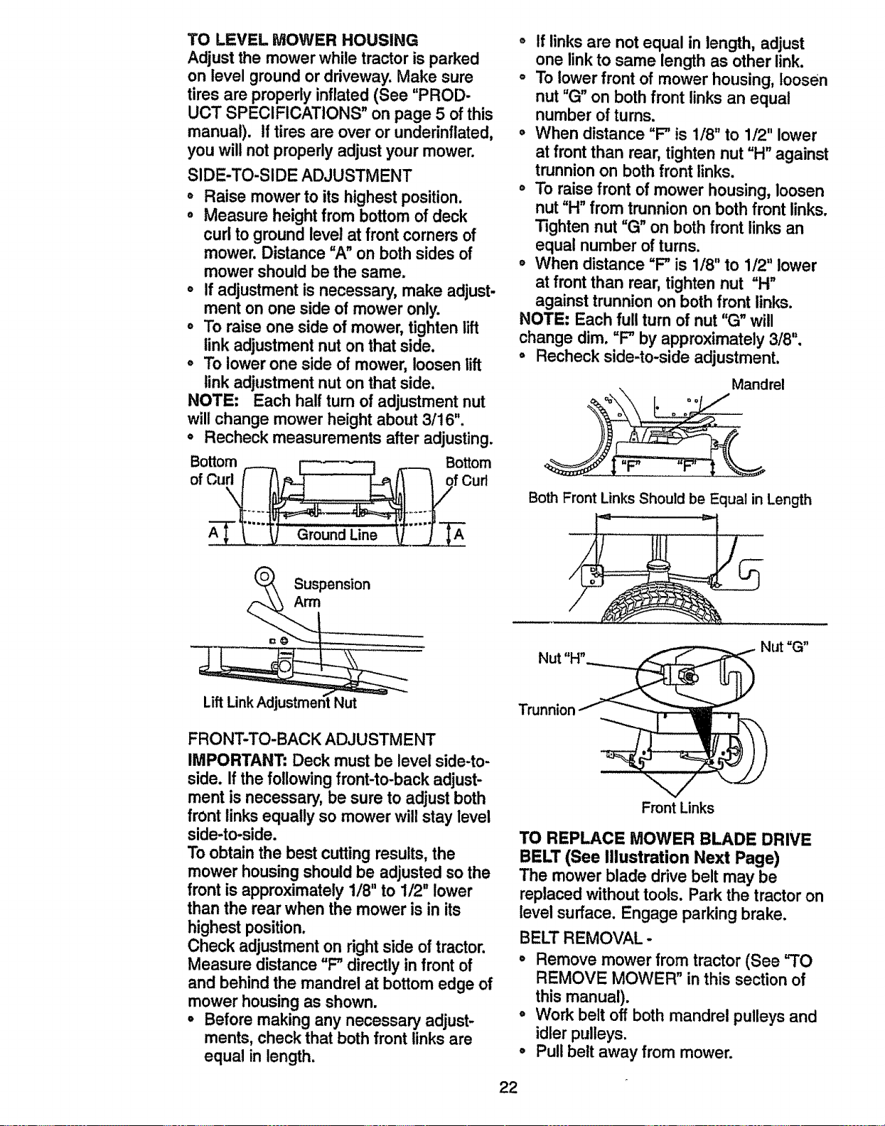
TO LEVEL MOWER HOUSING
Adjust the mower while tractor is parked
on level groundor driveway. Make sure
tires are properlyinflated(See "PROD-
UCT SPECIFICATIONS" on page 5 of this
manual). If tires are over or underinflated,
you will not properlyadjust your mower.
SIDE-TO-SIDE ADJUSTMENT
,, Raise mower to itshighest position.
,, Measure height from bottom of deck
curl to groundlevel at frontcomers of
mower. Distance "A" on both sides of
mower should be the same.
o If adjustment is necessary,make adjust-
ment on one side of mower only.
= To raise one side of mower, tightenlift
link adjustmentnut on that side.
,, To lower one side of mower, loosen lift
link adjustmentnut on that side.
NOTE: Each half turn of adjustment nut
will change mower heightabout 3/16".
• Recheck measurements after adjusting.
o
ofCu f Cud
,, If links are not equal in length, adjust
one link to same length as other link.
o To lower front of mower housing, loosen
nut "G" on both front links an equal
number of turns.
, When distance "F" is 1/8" to 1/2" lower
at front than rear, tighten nut "H" against
trunnion on both front links.
o To raise front of mower housing, loosen
nut "H" from trunnion on both front links.
Tighten nut "(3" on both front links an
equal number of turns.
° When distance "F" is 1/8" to 1/2" lower
at front than rear, tighten nut "H"
against trunnion on both front links.
NOTE: Each full turn of nut "G" will
change dim. "F" by approximately 3/8".
° Recheck side-to-side adjustment.
Mandrel
Both Front Links Should be Equal in Length
FRONT-TO-BACK ADJUSTMENT
IMPORTANT" Deck must be level side-to-
side. If the following front-to-back adjust-
ment is necessary,be sure to adjust both
front linksequally so mower willstay level
side-to-side.
To obtainthe best cuttingresults,the
mower housingshouldbe adjustedso the
front is approximately 1/8"to 1/2" lower
than the rear when the mower is in its
highestposition.
Check adjustmenton rightside of tractor.
Measure distance "F" directly in front of
and behind the mandrel at bottom edge of
mower housingas shown.
° Beforemaking any necessary adjust-
ments,check that bothfront linksare
equal in length.
Trunnion
Front Links
TO REPLACE MOWER BLADE DRIVE
BELT (See Illustration Next Page)
The mower blade drive belt may be
replaced withouttools. Park the tractor on
level surface. Engage parking brake.
BELT REMOVAL -
° Remove mower from tractor (See "TO
REMOVE MOWER" inthis section of
this manual).
° Work belt off both mandrel pulleys and
idler pulleys.
• Pull belt away from mower.
22
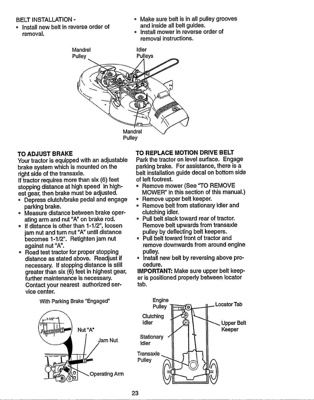
BELT INSTALLATION -
,, Install new belt in reverse order of
removal.
Mandrel
Pulley
o Make sure belt is in all pulley grooves
and inside all belt guides.
o Install mower in reverse order of
removal instructions.
Idler
Pulleys
Mandrel
Pulley
TO ADJUST BRAKE
Your tractor is equipped with an adjustable
brake system which is mounted on the
right side of the transaxle.
If tractor requires more than six (6) feet
stopping distance at high speed in high-
est gear, then brake must be adjusted.
° Depress clutch/brake pedal and engage
parking brake.
o Measure distance between brake oper-
ating arm and nut "A" on brake rod.
, If distance is other than 1-1/2", loosen
jam nut and turn nut "A" until distance
becomes i-1/2". Retighten jam nut
against nut "A".
o Road test tractor for proper stopping
distance as stated above. Readjust if
necessary. If stopping distance is still
greater than six (6) feet in highest gear,
further maintenance is necessary.
Contact your nearest authorized ser-
vice center.
With Parking Brake "Engaged"
Nut "A"
Jam Nut
;!Arm
TO REPLACE MOTION DRIVE BELT
Park the tractor on level surface. Engage
parking brake. For assistance, there is a
belt installation guide decal on bottom side
of left footrest.
o Remove mower (See "TO REMOVE
MOWER" in this section of this manual.)
o Remove upper belt keeper.
o Remove belt from stationary idler and
clutching idler.
o Pull belt slack toward rear of tractor.
Remove belt upwards from transaxle
pulley by deflecting belt keepers.
• Pull belt toward front of tractor and
remove downwards from around engine
pulley.
° Install new belt by reversing above pro-
cedure.
IMPORTANT: Make sure upper belt keep-
er is positioned properly between iocator
tab.
Engine
Pulley _ Locator Tab
Clutching I"-.Ji
Idler II_'_ _',.. Upper Belt
V II II Keepe
Stationary
Idler
Transaxle
Pulley
23
TO ADJUST STEERING WHEEL ALIGN-
MENT
If steering wheel crossbars are not hori-
zontal (left to right) when wheels are posi-
tioned straight forward, remove steering
wheel and reassemble per instructions in
the Assembly section of this manual.
FRONT WHEEL TOE-IN/CAMBER
The frontwheel toe-in and camber are not
adjustable on your tractor,if damage has
occurred to affectthe front wheel toe-in or
camber, contactyour nearest authorized
servicecenter.
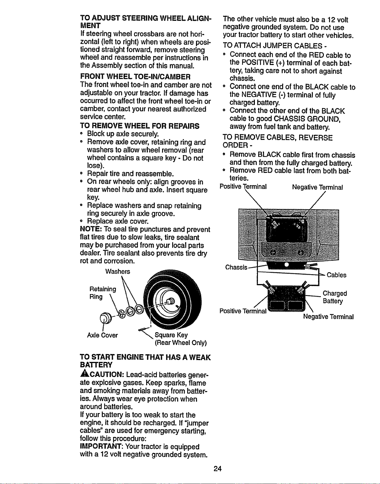
TO REMOVE WHEEL FOR REPAIRS
o Blockup axle securely.
° Remove axle cover, retainingring and
washers to allow wheel removal (rear
wheel contains a square key - Do not
lose).
° Repair tire and reassemble.
o On rear wheels only:align groovesin
rear wheel hub and axle. Insert square
key.
• Replace washers and snap retaining
ring securely in axle groove.
o Replace axle cover.
NOTE: To seal tire punctures and prevent
flat tires due to slow leaks, tire sealant
may be purchased from your local parts
dealer. Tire sealant also prevents tire dry
rot and corrosion.
Washers
The other vehicle must also be a 12 volt
negative grounded system. Do not use
your tractor battery to start other vehicles.
TO ATTACH JUMPER CABLES -
Connect each end of the RED cable to
the POSITIVE (+) terminal of each bat-
tery, taking care not to short against
chassis.
o Connect one end of the BLACK cable to
the NEGATIVE (-) terminal of fully
charged battery.
o Connect the other end of the BLACK
cable to good CHASSIS GROUND,
away from fuel tank and battery.
TO REMOVE CABLES, REVERSE
ORDER -
o Remove BLACK cable first from chassis
and then from the fully charged battery.
o Remove RED cable last from both bat-
teries.
PositiveTerminal Negative Terminal
Cables
Retaining
Ring
Axle Cover
TO START ENGINE THAT HAS A WEAK
BATTERY
,_CAUTION: Lead-acid batteries gener-
ate explosivegases. Keep sparks, flame
and smoking materials away from batter-
ies. Alwayswear eye protectionwhen
aroundbatteries.
If your battery is too weak to start the
engine, it should be recharged, if "jumper
cables"are used for emergency starting,
follow this procedure:
IMPORTANT: Yourtractor is equipped
with a 12 volt negative groundedsystem.
Positive Terminal
24
Charged
Battery
Negative Terminal
TO REPLACE HEADLIGHT BULB
• Raise hood.
o Pull bulb holder out of the hole in the
backside of the grill.
° Replace bulb in holder and push bulb
holder securely back into the hole in the
backside of the grill.
• Close hood.
INTERLOCKS AND RELAYS
Loose or damaged wiring may cause your
tractorto run poorly,stop running, or pre-
vent it from starting.
o Check wiring. See electrical wiring dia-
gram in the Repair Parts section of this
manual.
TO REPLACE FUSE
Replace with 30 amp automotive-type
plug-in fuse. The fuse holder is located
behind the dash.
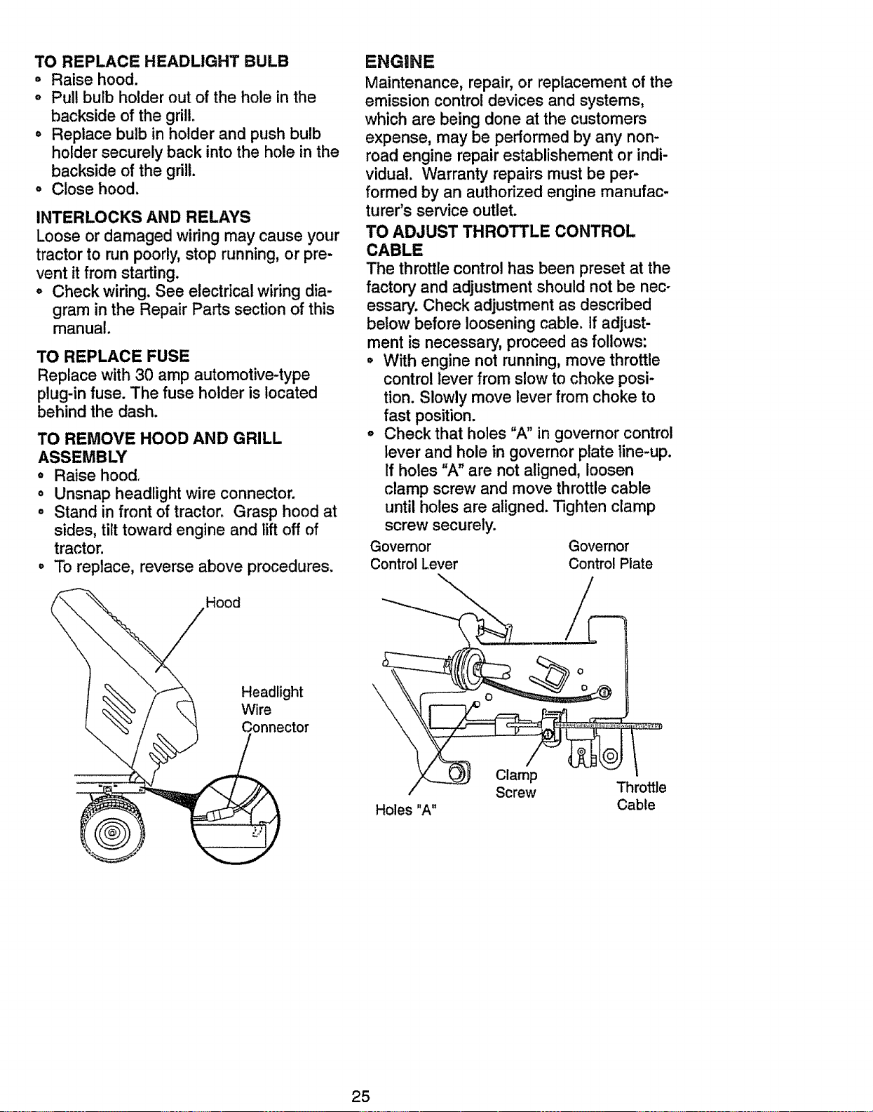
TO REMOVE HOOD AND GRILL
ASSEMBLY
° Raise hood_
• Unsnap headlight wire connector.
o Stand in front of tractor. Grasp hood at
sides, tilt toward engine and lift off of
tractor.
° To replace, reverse above procedures.
Hood
Headlight
Wire
Connector
ENGINE
Maintenance, repair, or replacement of the
emission control devices and systems,
which are being done at the customers
expense, may be performed by any non-
road engine repair establishement or indi-
vidual. Warranty repairs must be per-
formed by an authorized engine manufac-
turer's service outlet.
TO ADJUST THROTTLE CONTROL
CABLE
The throttle control has been preset at the
factory and adjustment should not be nec-
essary. Check adjustment as described
below before loosening cable. If adjust-
ment is necessary, proceed as follows:
o With engine not running, move throttle
control lever from slow to choke posi-
tion. Slowly move lever from choke to
fast position.
° Check that holes 'W' in governor control
lever and hole in governor plate ]ine-up.
If holes "A" are not aligned, loosen
clamp screw and move throttle cable
until holes are aligned. Tighten clamp
screw securely.
Governor Governor
Control Lever Control Plate
Holes "A"
Clamp
Screw
Throttle
Cable
25
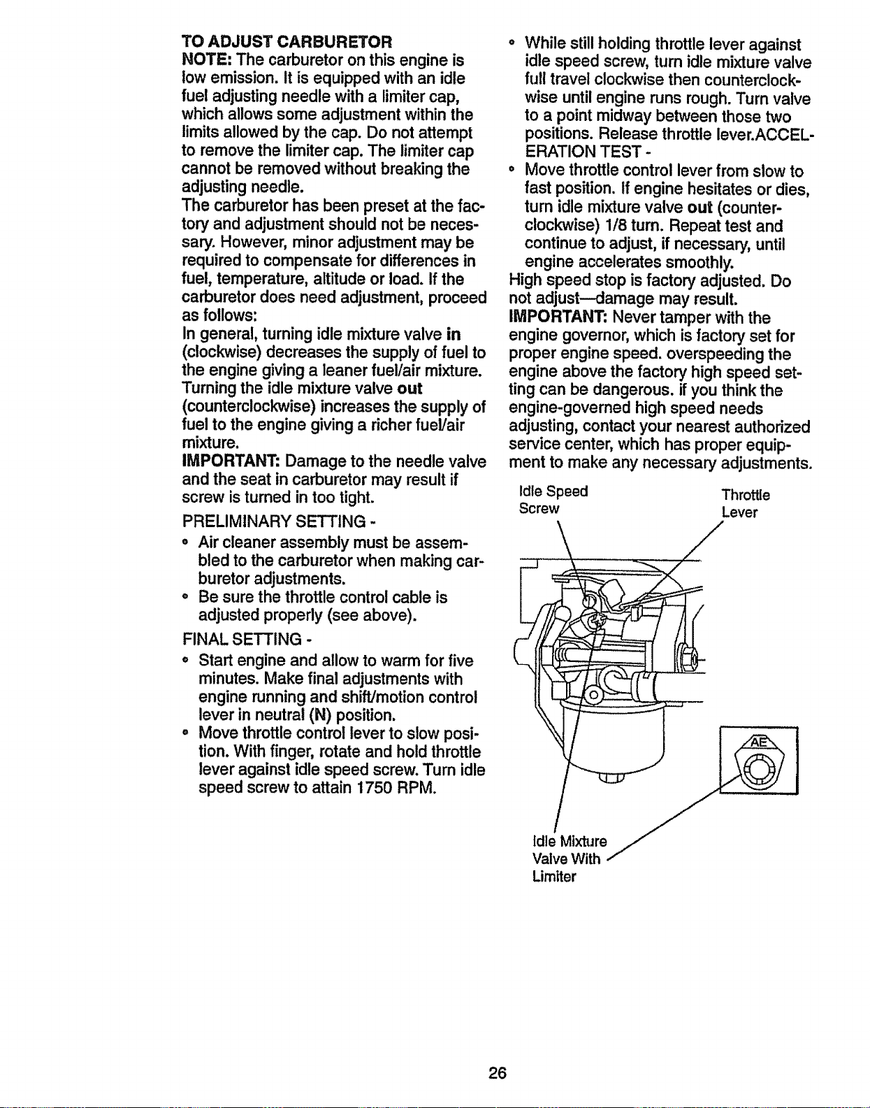
TO ADJUST CARBURETOR
NOTE: The carburetoron this engine is
towemission. It is equippedwith an idle
fuel adjustingneedle with a limitercap,
which allows some adjustment within the
limitsallowed by the cap. Do not attempt
to remove the limitercap. The limitercap
cannot be removed withoutbreaking the
adjustingneedle.
The carburetorhas been preset at the fac-
tory and adjustmentshould not be neces-
sary. However, minor adjustmentmay be
requiredto compensate for differences in
fuel, temperature, altitudeor load. If the
carburetor does need adjustment, proceed
as follows:
In general, turning idle mixture valve in
(clockwise)decreases the supply of fuel to
the engine giving a leaner fuel/air mixture.
Turning the idle mixturevalve out
(counterclockwise)increases the supply of
fuel to the engine givinga richerfueVair
mixture.
IMPORTANT: Damage to the needle valve
and the seat in carburetormay result if
screw is turned in too tight.
PRELIMINARY SETTING -
o Air cleaner assembly must be assem-
bled to the carburetorwhen making car-
buretor adjustments.
o Be sure the throttle control cable is
adjustedproperly (see above).
FINAL SETTING -
o Start engine and allow to warm for five
minutes. Make final adjustmentswith
engine runningand shift/motioncontrol
lever in neutral (N) position.
° Move throttlecontrol lever to slow posi-
tion. With finger, rotate and hold throttle
lever against idle speed screw. Turn idle
speed screwto attain 1750 RPM.
o While stillholdingthrottle lever against
idle speed screw, turn idle mixture valve
full travel cloclm_isethen counterclock-
wise untilengine runs rough.Turn valve
to a pointmidway between those two
positions.Release throttlelever.ACCEL-
ERATION TEST-
o Move throttlecontrol lever from slow to
fast position.If engine hesitates or dies,
turn idle mixture valve out (counter-
clockwise) 1/8 tum. Repeat test and
continueto adjust, if necessary,until
engine accelerates smoothly.
High speed stop is factory adjusted. Do
not adjust--damage may result.
IMPORTANT; Never tamper withthe
engine governor,which is factory set for
proper engine speed, overspeeding the
engine above the factory high speed set-
ting can be dangerous, if you thinkthe
engine-governed high speed needs
adjusting,contact your nearest authorized
service center, which has proper equip-
ment to make any necessary adjustments.
Idle Speed Throttle
Screw Lever
i
Limtter
26
Immediately prepare your tractorfor stor-
age at the end of the season or if the trac-
tor will not be used for 30 days or more.
,ACAUTiON: Never store the tractor with
gasoline inthe tank inside a building
where fumes may reach an open flame or
spark. Allow the engine to cool beforestor-
ing in any enclosure.
TRACTOR
Remove mower from tractor for winter
storage. This will allow you to clean it thor-
oughly.Remove all dirt,grease, leaves,
etc. Store in a clean, dry area.
o Clean entire tractor (See "CLEANING" in
the Maintenance section of this manual).
° Inspect and replace belts, if necessary
(See belt replacement instructionsin the
Service and Adjustmentssection of this
manual).
° Lubricate as shown inthe Maintenance
section of this manual.
° Be sure that all nuts, boltsand screws
are securely fastened. Inspect moving
partsfor damage, breakage and wear.
Replace if necessary.
o Touch up all rustedor chipped paint sur-
faces; sand lightlybefore painting.
BATTERY
• Fully charge the battery for storage.
° After a period of time in storage, battery
may require recharging.
° To help prevent corrosionand power
leakage during long periodsof storage,
battery cables shouldbe disconnected
and battery cleaned thoroughly(see "TO
CLEAN BATTERY AND TERMINALS" in
the Maintenance section of this manual).
o After cleaning, leave cables disconnect-
ed and place cables where they cannot
come in contactwith battery terminals.
° If battery is removed from tractorfor
storage, do not store battery directlyon
concrete or damp surfaces.
ENGINE
FUEL SYSTEM
IMPORTANT: It is important to prevent
gum depositsfrom formingin essentialfuel
system parts such as carburetor,fuel filter,
fuel hose, or tank duringstorage. Also,
experience indicates that alcoholblended
fuels (called gasohol or using ethanol or
methanol) can attract moisture which
leads to separation and formation of acids
during storage. Acidic gas can damage the
fuel system of an engine while in storage.
o Drain the fuel tank.
. Start the engine and let it run until the
fuel lines and carburetor are empty.
o Never use engine or carburetor cleaner
products in the fuel tank or permanent
damage may occur.
° Use fresh fuel next season.
NOTE: Fuel stabilizer is an acceptable
alternative in minimizing the formation of
fuel gum deposits during storage. Add sta-
bilizer to gasoline in fuel tank or storage
container. Always follow the mix ratio
found on stabilizer container. Run engine
at least 10 minutes after adding stabilizer
to allow the stabilizer to reach the carbure-
tor. Do not drain the gas tank and carbure-
tor if using fuel stabilizer.
ENGINE OIL
Drain oil (with engine warm) and replace
with clean engine oil. (See "ENGINE" in
the Maintenance section of this manual).
CYLINDERS
° Remove spark plug(s).
° Pour one ounce of oil through spark
plug hole(s) into cylinder(s).
• Turn ignition key to "START" position for
a few seconds to distribute oil.
° Replace with new spark plug(s),
OTHER
° Do not store gasoline from one season
to another.
° Replace your gasoline can if itstarts to
rust. Rust and/or dirt in your gasoline
will cause problems.
* If possible, store your tractor indoors
and cover itto give protectionfrom dust
and dirt.
° Cover your tractorwith a suitablepro-
tective cover that does not retainmois-
ture. Do not use plastic. Plastic cannot
breathe, which allows condensationto
form and cause your tractorto rust.
IMPORTANT: Never cover tractor while
engine and exhaust areas are still warm,
27
TROUBLESHOOTING CHART
PROBLEM CAUSE
Will not start o Out of fuel.
o Engine not"CHOKED"
properly.
o Engine flooded.
Hard to start
Engine will not turn
over
° Bad spark plug.
o Dirty air filter.
o Dirty fuel filter.
o Water in fuel.
o Loose or damaged wiring.
o Carburetor out of adjust-
ment.
° Engine valves out of
adjustment.
° Dirty air filter.
o Bad spark plug.
= Weak or dead battery.
o Dirty fuel filter.
° Stale or dirty fuel.
o Loose or damaged wiring.
° Carburetor out of adjust-
ment.
o Engine valves out of
adjustment.
= Clutch/brake pedal not
depressed.
,, Attachment clutch is
engaged.
= Weak or dead battery.
° Blown fuse.
° Corroded battery termi-
nals.
• Loose or damaged wiring.
° Faulty ignition switch.
° Faulty solenoid or starter.
° Faulty operator presence
switch(es).
o Weak or dead battery.
° Corroded battery termi-
nals.
Engine clicks but
willnot start
CORRECTION
= Fill fuel tank.
o See "TO START ENGINE" in
Operation section.
o Wait several minutes before
attemptingto start.
o Replace spark plug,
• Clean/replace air filter,
° Replace fuel filter,
° Drain fuel tank and carbure-
tor, refilltank with fresh
gasoline and replace fuel fil-
ter.
• Check all wiring.
° See "To Adjust Carburetor"
in Service and Adjustments
section.
° Contact an authorized ser-
vice center.
o Clean/replace airfilter.
° Replace spark plug.
o Recharge or replace battery.
° Replace fuel filter.
o Drain fuel tank and refill with
fresh gasoline.
° Check all wiring.
° See "To Adjust Carburetor"
in Service and Adjustments
section.
° Contact an authorized ser-
vice center.
• Depress clutch!brake pedal.
, Disengage attachment
clutch.
° Recharge or replace battery.
• Replace fuse.
° Clean battery terminals.
• Check all wiring.
° CheckJreplace ignition
switch.
° CheckJreplace solenoid or
starter.
° Contact an authorized ser-
vice center.
° Recharge or replace battery.
° Clean battery terminals.
28
TROUBLESHOOTING CHART
PROBLEM CAUSE
Engine clicks but , Loose or damaged wiring.
will not start o Faulty solenoid or starter.
(cont'd)
Loss of power
° Cutting too much
grass/too fast.
o Throttle in "CHOKE" posi-
tion.
, Build-up of grass, leaves
and trash under mower.
o Dirty air filter.
- Low oil level/dirty oil.
° Faulty spark plug.
° Dirty fuel filter.
- Stale or dirty fuel.
Water in fuel.
o Spark plug wire loose.
o Dirty engine air
screepJfins.
o Dirty/clogged muffler.
CORRECTION
Check all wiring.
Check/replace solenoid or
starter.
o
°
o Set in "Higher Cut" posi-
tion/reduce speed.
° Adjust throttle control.
° Loose or damaged widng.
° Carburetor out of adjust-
ment.
° Engine valves out of
adjustment.
o Clean underside of mower
housing.
• Clean/replace air filter.
° Check oil level/change oil.
, Clean and regap or change
spark plug.
° Replace fuel filter.
° Drain fuel tank and refill with
fresh gasoline.
° Drain fuel tank and carbure-
tor, refill tank with fresh gaso-
line and replace fuel filter.
° Connect and tighten spark
plug wire.
° Clean engine air screen/fins.
Excessive vibration
° Clean/replace muffler.
° Check all wiring.
° See "To Adjust Carburetor" in
Service and Adjustments
section.
° Contact an authorized ser-
vice center.
Replace blade. Tighten blade
bolt.
Replace blade mandrel.
Tighten loose part(s).
Replace damaged pads.
° Worn, I_ent or loose blade. °
° Bent blade mandrel.
° Looseldamaged part(s). °
o
Engine continues to
run when opera-
tor leaves seat
with attachment
clutch engaged
• Faulty operator-safety
presence controlsystem.
Check wiring, switches and
connections. If not
corrected, contact an autho-
rized service center.
Poor cut - uneven
° Worn, bent or loose blade.
° Mower deck not level.
o Buildup of grass, leaves,
and trash under mower.
° Bent blade mandrel.
o Clogged mower deck vent
holes from buildup of
° Replace blade. Tighten blade
bolt.
° Level mower deck.
o Clean underside of mower
housing.
, Replace blade mandrel.
o Clean around mandrels to
open vent holes.
29
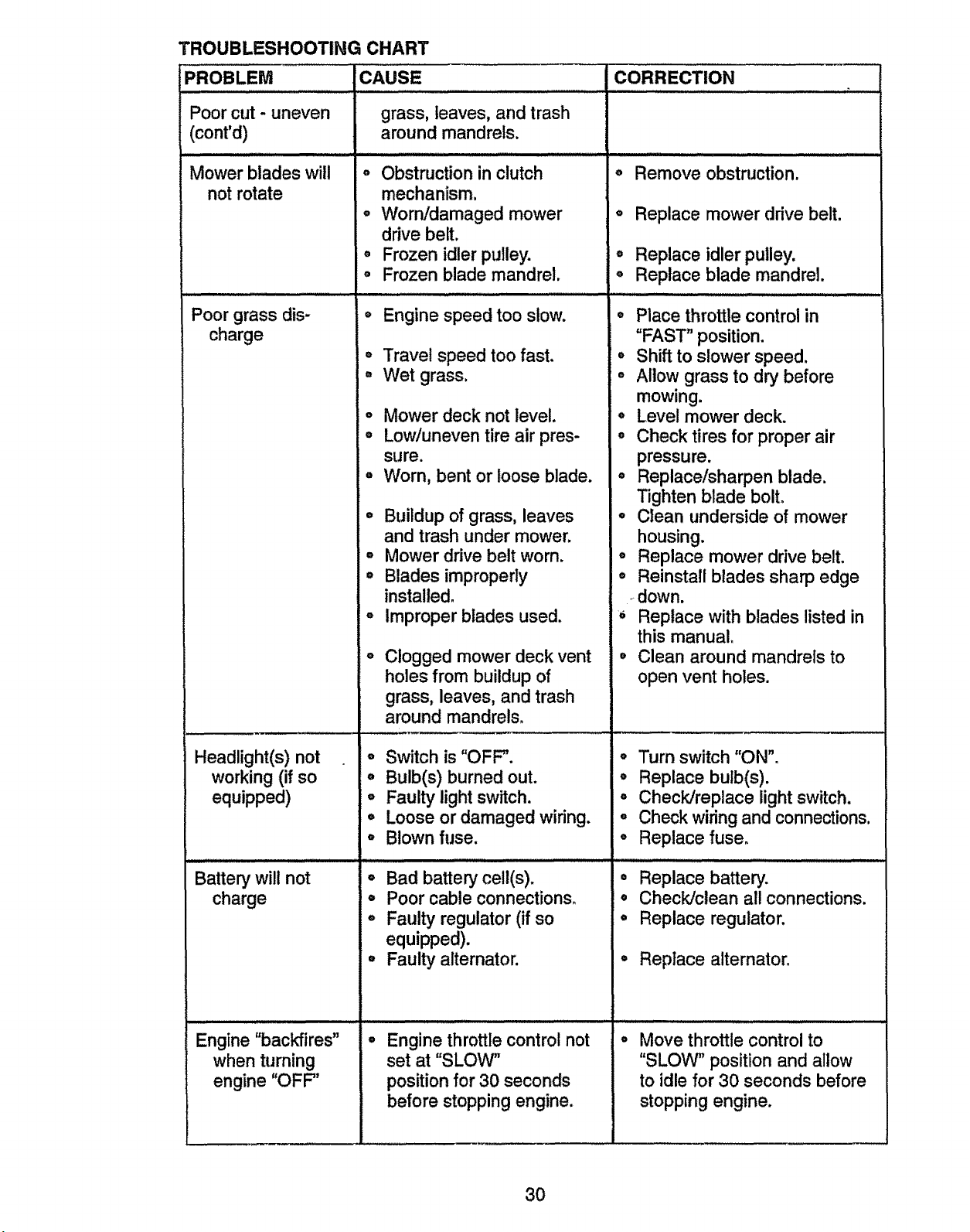
PROBLEM
:'oor cut - uneven
(conrd)
Mower blades will
not rotate
TROUBLESHOOTING CHART
CAUSE
.i,i i,J,,J, iJ .........i .i ii i i
grass, leaves, and trash
around mandrels.
Poor grass dis-
charge
Headlight(s) not
working (if so
equipped)
Battery will not
charge
Engine "backfires"
when turning
engine "OFF"
o Obstruction in clutch
mechanism.
o Worn/damaged mower
drive belt.
° Frozen idler pulley.
° Frozen blade mandrel.
o Engine speed too slow.
,, Travel speed too fast.
° Wet grass.
° Mower deck not leve!.
• Low/uneven tire air pres-
sure.
, Worn, bent or loose blade.
° Buildup of grass, leaves
and trash under mower.
° Mower drive belt worn.
,, Blades improperly
installed.
° Improper blades used.
Clogged mower deck vent
holes from buildup of
grass, leaves, and trash
around mandrels.
= Switch is "OFF".
° Bulb(s) burned out.
o Faulty light switch.
,, Loose or damaged wiring.
° Blownfuse.
o Bad battery cell(s).
° Poor cable connections.
° Faulty regulator(if so
equipped).
° Faulty alternator.
Engine throttle control not
set at "SLOW"
position for 30 seconds
before stopping engine.
CORRECTION
i ,lli i i, i ...H F
o Remove obstruction.
o Replace mower drive belt.
,, Replace idler pulley.
o Replace blade mandrel.
° Place throttle control in
"FAST" position.
o Shift to slower speed.
o Allow grass to dry before
mowing.
° Level mower deck.
• Check tires for proper air
pressure.
° Replace/sharpen blade.
Tighten blade boll
° Clean underside of mower
housing.
° Replace mower drive belt.
° Reinstall blades sharp edge
down.
Replace with blades listed in
this manual.
,, Clean around mandrels to
open vent holes.
° Turn switch "ON".
• Replace bulb(s).
° Check/replace light switch.
° Check wiring and connections.
° Replace fuse.
,, ii ill illlll i i
• Replace battery.
• Check/clean all connections.
° Replace regulator.
• Replace alternator.
Move throttle control to
"SLOW" position and allow
to idle for 30 seconds before
stopping engine.
3O
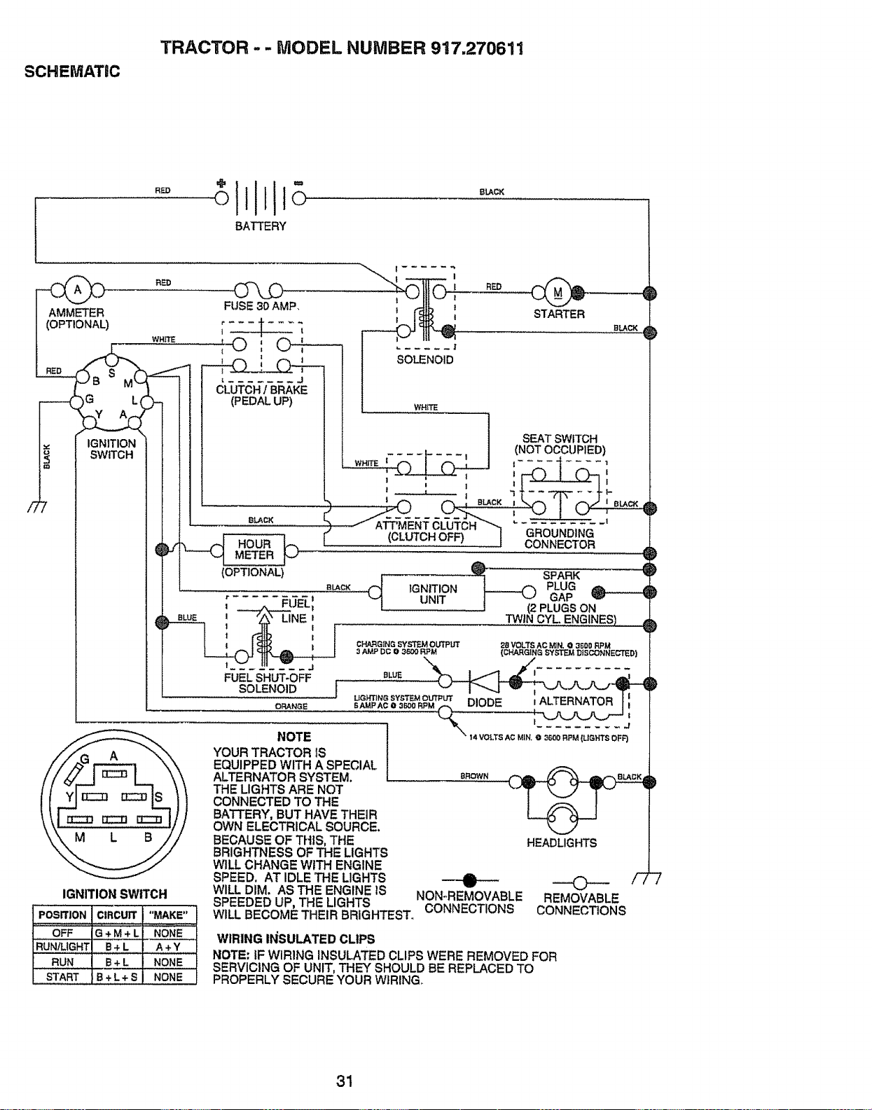
SCHEMATIC
TRACTOR -- MODEL NUMBER 917.270611
i!1 °
"° o11to
BATTERY
RED
IGNITION SWITCH
PosrrJoNczRcurr"MAKe"
OFF G+M÷L NONE
RUN/LIGHT[ B÷ L . A +Y
RUN B+ L
START B + L + S
STARTER
BLACK
BROWN
HEADLIGHTS
NOTE
YOUR TRACTOR IS
EQUIPPED WITH A SPECIAL
ALTERNATOR SYSTEM.
THE LIGHTS ARE NOT
CONNECTED TO THE
BATTERY, BUT HAVE THEIR
OWN ELECTRICAL SOURCE.
BECAUSE OF THIS, THE
BRIGHTNESS OF THE LIGHTS
WILL CHANGE WITH ENGINE
SPEED. AT IDLE THE LIGHTS
WILL DIM. AS THE ENGINE tS
©
REMOVABLE
CONNECTIONS
O
NON°REMOVABLE
SPEEDED UP, THE LIGHTS CONNECTIONS
WILL BECOME THEIR BRIGHTEST.
WIRING INSULATED CLIPS
NOTE: IF WIRING INSULATED CLIPS WERE REMOVED FOR
NONE SERVICING OF UNIT, THE'{ SHOULD BE REPLACED TO
NONE PROPERLY SECURE YOUR WIRING
31
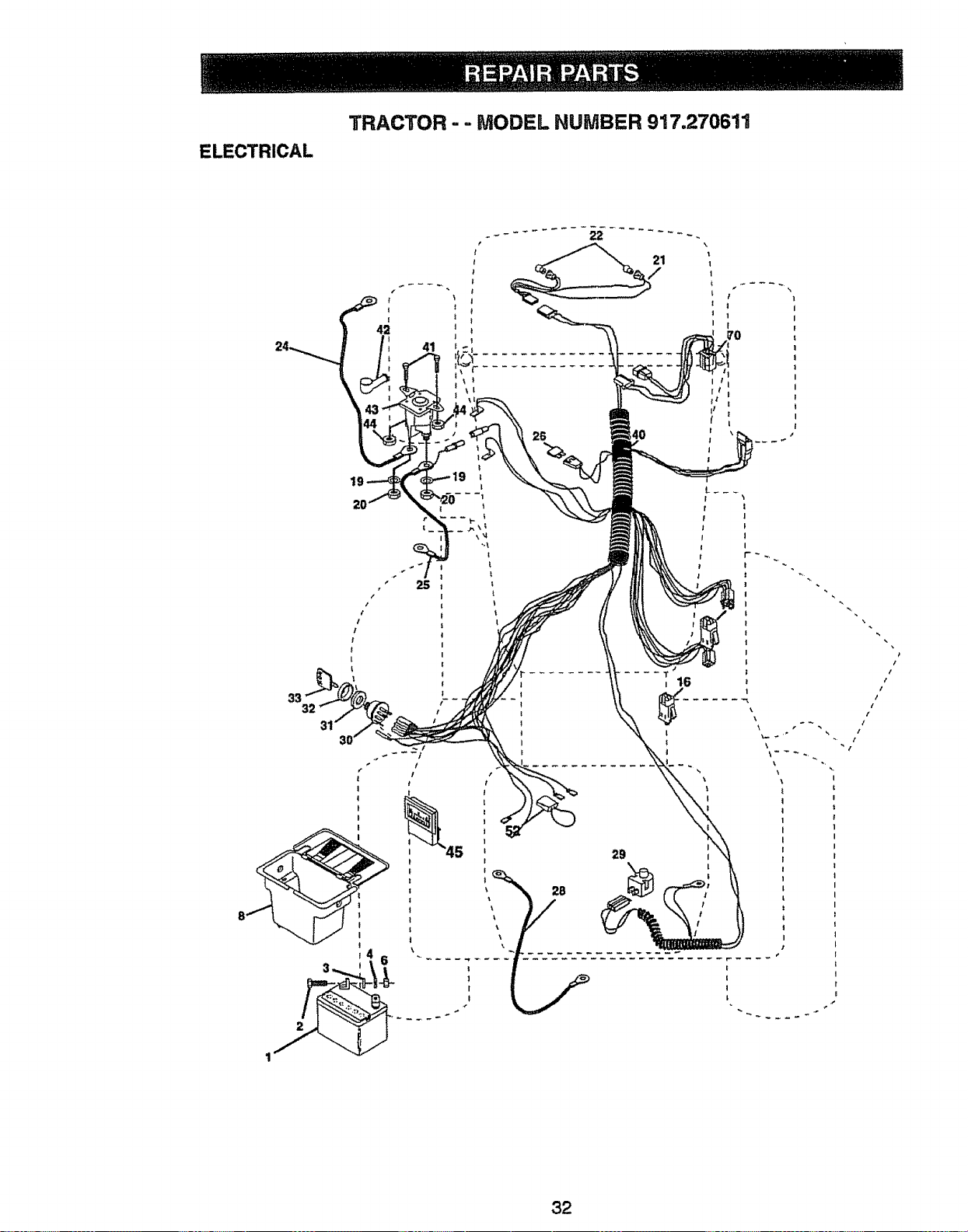
ELECTRICAL
TRACTOR - - MODEL NUMBER 917.270611
26
33
i I
f !
I
i I
i I
i I
32

ELECTRICAL
TRACTOR - - MODEL NUMBER 917.270611
KEY PART
NO. NO. DESCRIPTION
1 144925
2 74760412
3 S'TD551025
4 STD551125
6 STD541025
8 156417
16 153664
19 STD551125
20 73350400
21 147430
22 4152J
24 4799J
25 146147
26 108824X
28 4207J
29 121305X
30 140301
31 12421tX
32 141226
33 109310)(
40 156442
41 71110408
42 131563
43 145673
44 73640400
45 121433X
52 141940
70 140422
NOTE:
Battery12VOLT25 AMP
Bolt Hex Hd 1/4-20uncx 3/4
Washer9/32 x 5/8 x 16 Ga
WasherLockHvyHettcal1/4
NutFin Hex I/4-20 Uric
Case Battery
Switch,interlockPush-In
WasherLock1/4
NutJam Hex I/4-20 Unc
HarnessAsmUght W/4152j
BulbLight#1156
Cable Battery 6 Ga 11"red
CableBattery6 Ga w/16 wire red
Fuse 30AMP Auto Green
CableGround 6 Ga !2" black
Switch Plunger Nc Gray
SwitchIgn 4 Pos
Nut Ignition
Cover Sw Key BIk 1 25 TextSLT
Key Ign MoldedCraftsman
Harness lgn Man Cl Am Hm 97
Bolt Blk.Fin Hex 1/4-20 Unc x I/2
CoverTerminalRed
Solenoid
Nut Keps Blk Hex 1/4-20Unc
Ammeter Rectangular6 Amp
ProtectionWire Loop
Hamass EngineB&S 14OHV
All componentdimensions give in U,So inches
1 inch = 25.4 mm
33
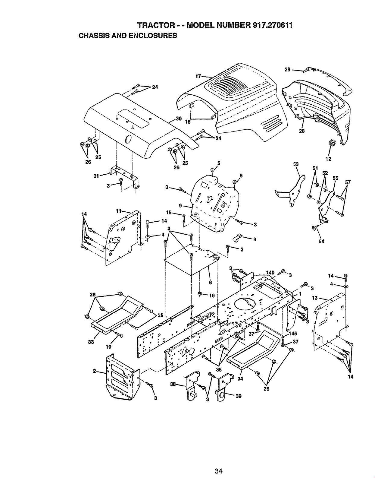
TRACTOR ,, ,- MODEL NUMBER 9'17.270611
CHASSIS AND ENCLOSURES
29
25 5
28
5
2B
12
2
55
57
14
15-._ °
3
54
26
33
10
35
14
34
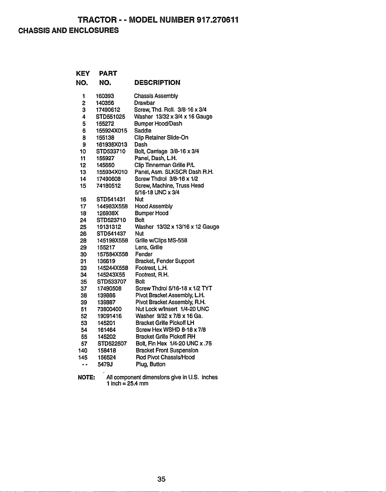
TRACTOR - -. MODEL NUMBER 917=270611
CHASSIS AND ENCLOSURES
KEY PART
NO. NO. DESCRIPTION
1 !60393 ChassisAssembly
2 140356 Drawbar
3 17490612 Screw,Thd, Rollo3/8_16x 3/4
4 STD551025 Washer 13/32 x 3/4 x 16 Gauge
5 155272 BumperHood/Dash
6 155924)(015 Saddle
8 155138 ClipRetainerSlide-On
9 161938)(013 Dash
10 STD533710 Bolt,Carriage 3/8-16 x 3/4
11 155927 Panel, Dash,L.H.
12 145660 ClipTinnermanGrille P/L
13 155934X010 Panel,AsmoSLKSCR DashR.H.
14 17490608 ScrewThdrol 3/8-16 x 1/2
15 74180512 Screw,Machine,TrussHead
5/16-18 UNC x 3/4
16 STD541431 Nut
17 144983X558 HoodAssembly
18 126938X BumperHood
24 STD523710 Bolt
25 19131312 Washer 13/32 x 13/16 x t2 Gauge
26 STD541437 Nut
28 145198X558 Grillew/ClipsMS-558
29 155217 Lens,Grille
30 157564X558 Fender
31 136619 Bracket, FenderSupport
33 145244X558 Footrest,L.Ho
34 145243X55 Footrest,R.H.
35 STD533707 Bolt
37 17490508 ScrewThdrol5/16-18 x 1/2TYT
38 139886 PivotBracketAssembly, LH.
39 t39887 PivotBracketAssembly, R.H.
51 73800400 Nut Lockw/Insert 1/4-20UNC
52 19091416 Washer 9/32 x 7/8 x 16 Ga,
53 145201 Bracket Grille Pickoff LH
54 161464 ScrewHex WSHD 8-_18x 718
55 145202 BracketGrillePlckoffRH
57 STD522507 Bolt,FinHex 1/4_20UNC x .75
140 158418 Bracket FrontSuspension
145 156524 RodPivotChassis/Hood
.- 5479J Plug, Button
NOTE:
r,
Allcomponentdimensionsgive in UoS. inches
1 inch= 25,4 mm
35
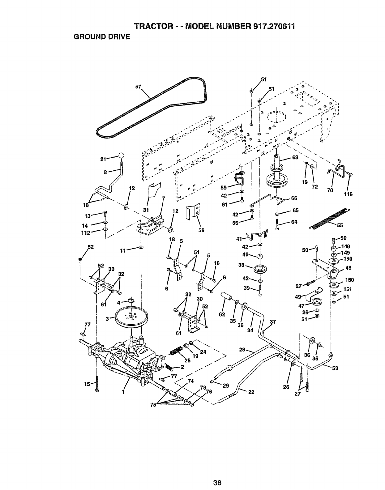
TRACTOR - - MODEL NUMBER 917.270611
GROUND DRIVE
57
48
150
151
51
i
i
i
i
53
22
i
26
27
36
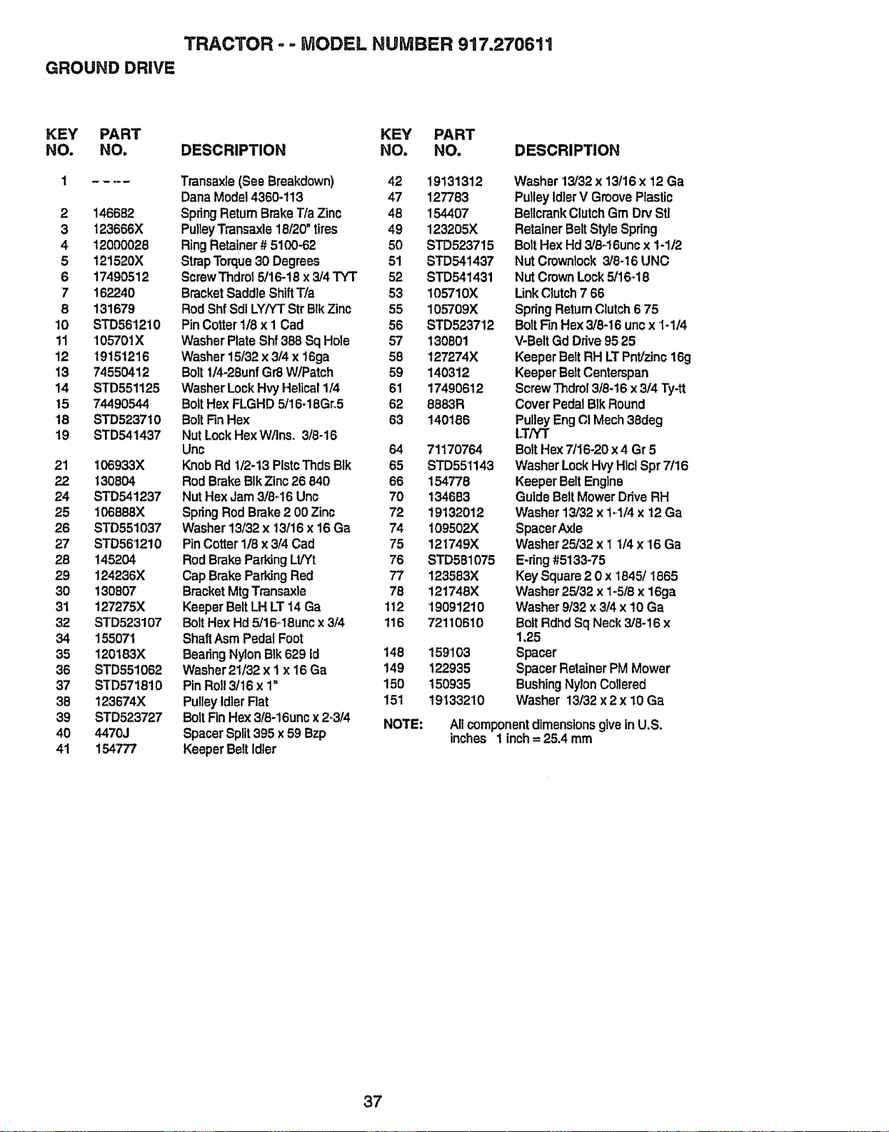
TRACTOR - = MODEL NUMBER 917.270611
GROUND DRIVE
KEY PART KEY PART
NO. NO. DESCRIPTION NO. NO.
1 .... Transaxle(See Breakdown) 42 19131312
DanaModel4360-il 3 47 127783
2 146682 SpringReturnBrakeT/a Zinc 48 154407
3 123666X PulleyTransaxle18120"tires 49 123205X
4 12000028 Ring Retainer# 5100-62 50 STD5237t5
5 121520X StrapTorque30 Degrees 51 STD541437
6 17490512 ScrewThdrol5/16-18x 3/4 TYT 52 STD541431
7 162240 BracketSaddleShiftT/a 53 105710X
8 131679 RodShfSdlLY/YTStr BlkZinc 55 105709X
10 STD56t210 PinCotter1!8x 1 Cad 56 STD523712
11 t05701X WasherPlateShf388 Sq Hole 57 130801
12 19151216 Washer15t32x 3/4 x 16ga 58 127274X
13 74550412 Bolt1/4-28unfGr8 W/Patch 59 140312
14 STD551125 WasherLockHvyHelical1/4 61 17490612
15 74490544 BoltHex FLGHD 5/16-18Gr,5 62 8883R
18 STD5237t0 BoltFin Hex 63 140186
19 STD541437 Nut Lock HexW!Ins, 3/8-16
Unc 64
Knob Rd 1/2-13 PlstcThdsBIk 65
Rod BrakeBIk Zinc 26 840 66
Nut Hex Jam 3/8-t6 Unc 70
SpringRod Brake 2 00 Zinc 72
Washer 13/32x t3/16 x 16Ga 74
PinCotter1/8 x 3/4 Cad 75
Rod Brake Parking LWt 76
Cap BrakeParkJngRed 77
BracketMtg Transaxle 78
KeeperBelt LH LT 14 Ga 112
Bolt Hex Hd 5/16_18uncx 3/4 116
ShaftAsmPedal Foot
BeadngNylon BIk629 Id 148
Washer21/32 x 1 x 16 Ga 149
Pin Roll 3/16 x 1" 150
Pulley Idler Flat 151
Bolt Fin Hex3/8-16uncx 2,,3/4 NOTE:
SpacerSplit395 x 59 Bzp
KeeperBelt Idler
21 106933X
22 130804
24 STD541237
25 106888X
26 STD551037
27 STD561210
28 145204
29 124236X
30 130807
31 127275X
32 STD523107
34 155071
35 120!83X
36 STD55!062
37 STD571810
38 123674X
39 STD523727
40 4470J
41 154777
DESCRIPTION
71170764
STD55t143
154778
134683
19132012
109502X
121749X
STD581075
123583X
121746X
19091210
72110610
159103
122935
150935
19133210
Washer13/32x 13/16x 12Ga
PulleyIdlerV GroovePlastic
Bellcr'a.nkClutchGm Drv St]
RetainerBeltStyleSpring
BoltHexHd 3/8.,16uncx 1-1/2
NutCrownlock3/8-16 UNC
NutCrownLock5/16-18
Link Clutch7 66
SpringReturnClutch6 75
Bolt FinHex3/8-16 uncx 1-114
V-BeltGd Drive9525
KeeperBettRH LTPnt/zinc16g
KeeperBeltCenterspan
ScrewThdro1318-16x 3/4 Ty-tt
CoverPedal BlkRound
PulleyEngCI Mech38deg
LT/YT
BoltHex 7/16-20x 4 Gr 5
WasherLockHvyHlclSpr7/16
KeeperBelt Englne
GuideBelt MowerDriveRH
Washer 13/32 x t*,1/4x 12 Ga
SpacerAxle
Washer25/32 x I t/4 x 16 Ga
E-ring#5133-75
Key Square2 0 x 1845/1865
Washer25/32 x 1-5/8 x 16ga
Washer9t32 x 3/4 x 10 Ga
BoltRdhd SqNeck 3/8-16 x
1.25
Spacer
SpacerRetainerPM Mower
BushingNylonCollered
Washer 13/32 x2 x 10 Ga
All component dimensions give in U,S.
inches 1 inch = 25.4 mm
37
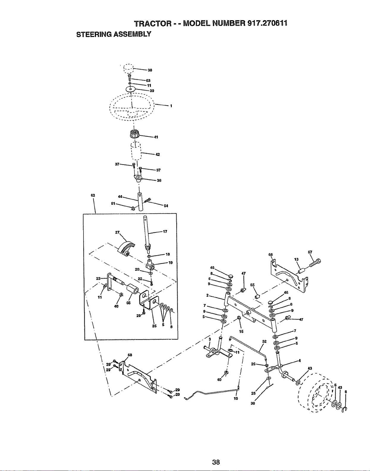
TRACTOR - - MODEL NUMBER 917.270611
STEERING ASSEMBLY
, _,42
62
117
\
'\
J
4G
47
10
2B
3O
38
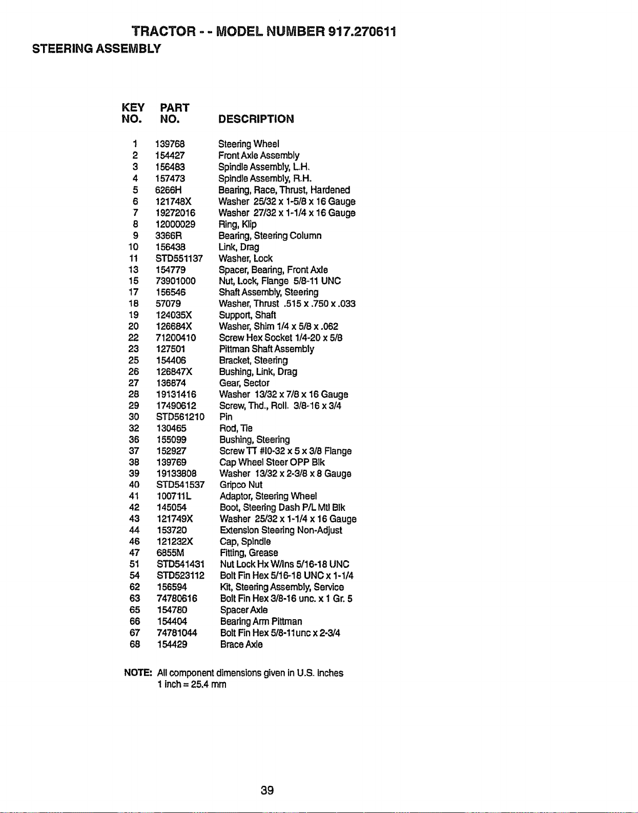
TRACTOR - .. MODEL NUMBER 917.270611
STEERING ASSEMBLY
KEY PART
NO. NO. DESCRIPTION
I 139768
2 154427
3 156483
4 157473
5 6266H
6 121748X
7 19272016
8 12000029
9 3366R
10 156438
11 STD551137
t3 154779
15 73901000
17 156546
18 57079
19 124035X
20 126684X
22 7'1200410
23 127501
25 154406
26 126B47X
27 136874
28 19131416
29 17490612
30 STD561210
32 130465
36 t55099
37 152927
38 139769
39 19133806
40 STD541537
41 100711L
42 145054
43 121749X
44 153720
46 121232X
47 6855M
51 STD541431
54 STD523112
62 156594
63 74780616
65 154780
66 154404
67 74781044
68 t54429
SteeringWheel
FrontAxleAssembly
SpindleAssembly,LH.
SpindleAssembly,R+H+
Bearing,Race,Thrust,Hardened
Washer 25/32 x 1-5/8 x t6 Gauge
Washer 27132x 1-1/4 x t6 Gauge
Ring,Klip
Bearing,SteeringColumn
Link,Drag
Washer,Lock
Spacer,Bearing,FrontAxle
Nut,Lock,Flange 518+11UNG
ShaftAssembly,Steering
Washer,Thrust .515 x .750 x .033
Support,Shaft
Washer,Shim 1/4 x 5/8 x .062
ScrewHex Socket1/4-20x 5/8
PiP,manShaft Assembly
Bracket,Steering
Bushing,Unk, Drag
Gear,Sector
Washer 13/32 x 7/8 x 16 Gauge
Screw,Thd_,Roll+ 318+16x 5/4
Pin
Rod,Tie
Bushing,Steering
ScrewTT #10+32x 5 x 3/8 Range
Cap Wheel Steer OPP Blk
Washer 13/32x 2-3/8 x 8 Gauge
Gripco Nut
Adaptor,SteeringWheel
Boot, SteeringDash P/L.Mtl Btk
Washer 25/32 x 1-1/4 x 16 Gauge
ExtensionSteeringNon-Adjust
Cap, Spindle
Fitting,Grease
NutLockHx W/Ins 5/16-18 UNC
BoltFin Hex 5/t6-18 UNCx 1-1/4
Kit, SteeringAssembly,Service
BoltFinHex3/8-16 unc.x t Gr.5
SpacerAxle
BearingArmPitt.man
BoltFinHex 518-1tuncx2-3/4
BraceAxle
NOTE: All componentdimensions given in U.S. inches
1inch= 25.4 mm
39
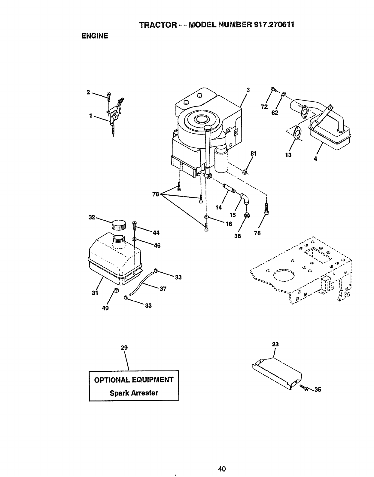
ENGINE
TRACTOR - - MODEL NUMBER 917.270611
3
33
7
4
/
29
!,
OPTIONAL EQUIPMENT
Spark Arrester
23
4O
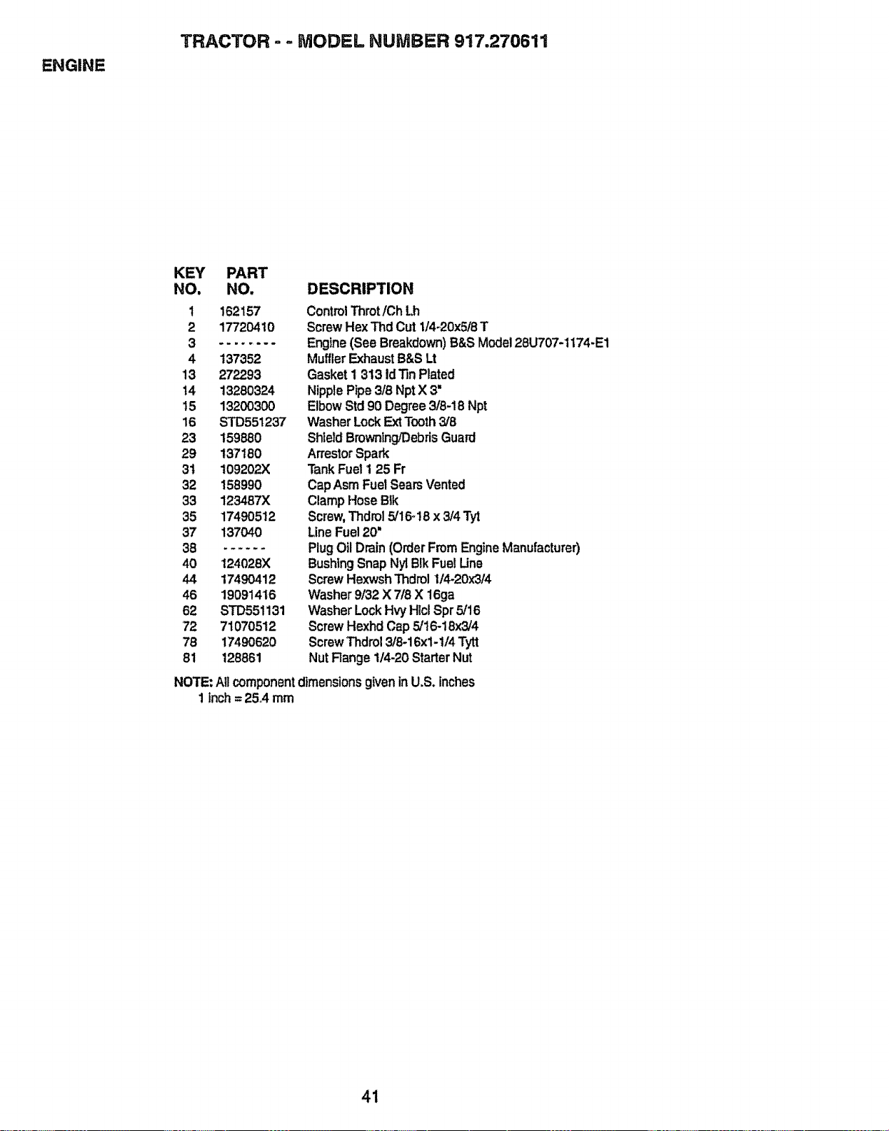
ENGINE
TRACTOR - .. MODEL NUMBER 917.270611
KEY PART
NO, NO. DESCRIPTION
1 162157
2 17720410
4 137352
13 27293
14 13280324
15 13200300
16 STD551237
23 159880
29 137160
31 109202)(
32 158990
33 123487X
35 17490512
37 137040
38 ......
40 124028X
44 17490412
46 19091416
62 STD551131
72 71070512
78 17490620
81 128861
Control Throt/ChLh
Screw Hex Thd Cut 1/4-20x5/8T
Engine(See Breakdown) B&SModel 28U707-1174-E1
Muffler ExhaustB&SLt
Gasket1 313 ldTin Plated
NipplePipe 3/8 NptX 3"
ElbowStd 90 Degree3/6-18 Npt
WasherLockExtTooth3/8
ShieldBrowning/DebrisGuard
ArrestorSpark
TankFuel 1 25 Fr
CapAsmFuel SearsVented
ClampHose Blk
Screw,Thdrol5/16°18x 3/4 Tyt
Line Fuel20"
PlugOil Drain(OrderFromEngineManufacturer)
BushingSnapNyl BlkFue!Une
ScrewHexwshThdrolI14-20x314
Washer9/32 X 7/8 X 16ga
WasherLockHvyHlclSpr5/16
ScrewHexhdCap 5/16-18x3/4
ScrewThdrol3/6-16x1-1/4Tytt
NutRange 1/4-20 StarterNut
NOTE: All component dimensions given in U.S. inches
1 inch= 25A mm
41
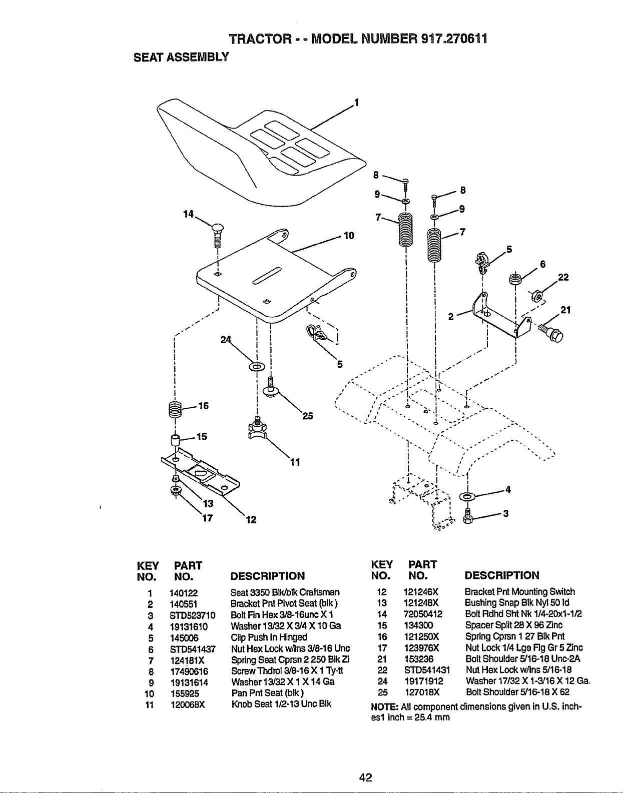
TRACTOR -.. MODEL NUMBER 917o270611
SEAT ASSEMBLY
i
I
5
2
I
i i
KEY
NO.
1
2
3
4
5
6
7
8
9
10
1t
PART
NO.
140122
140551
STD523710
19131610
145OO6
STD541437
124181X
17490616
19131614
155925
120068X
DESCRIPTION
Seat3350 Btk/olkCraftsman
BracketPnt PivotSeat(btk)
BoltRn Hex3/8-16un¢X 1
Washer13/32 X 3/4 X 10 Ga
ClipPushIn Hinged
NutHex Lockw/ins3/8-16 Unc
SpringSeatCprsn2 250 BIkZi
ScrewThdrol3/8-16 X 1Ty-t_
Washer13/32X 1 X 14 Ga
Pan PntSeat(blk)
KnobSeat1/2-13UncBlk
KEY PART
NO. NO. DESCRIPTION
12 121246X
13 121248)(
14 72050412
15 134300
16 121250X
17 123976X
21 153236
22 STD541431
24 19171912
25 127018)(
BracketPntMountingSwitch
BushingSnapB1kNy150Id
BoltRdhdSht Nk 1/4-20x1-1/2
SpacerSplit28 X 96 Zinc
SpringCprsn1 27 Blk Pnt
NutLock114LgeRg Gr 5 Zinc
Bo_tShoulder5/16-18Unc-2A
NutHexLockw/Ins5/16-18
Washer17/32 X 1-3/16 X 12 Ga,
BoltShoulder5/16-t8 X62
NOTE: Atl componentdimensionsgiven inU.S. inch-
esl inch= 25A mm
42
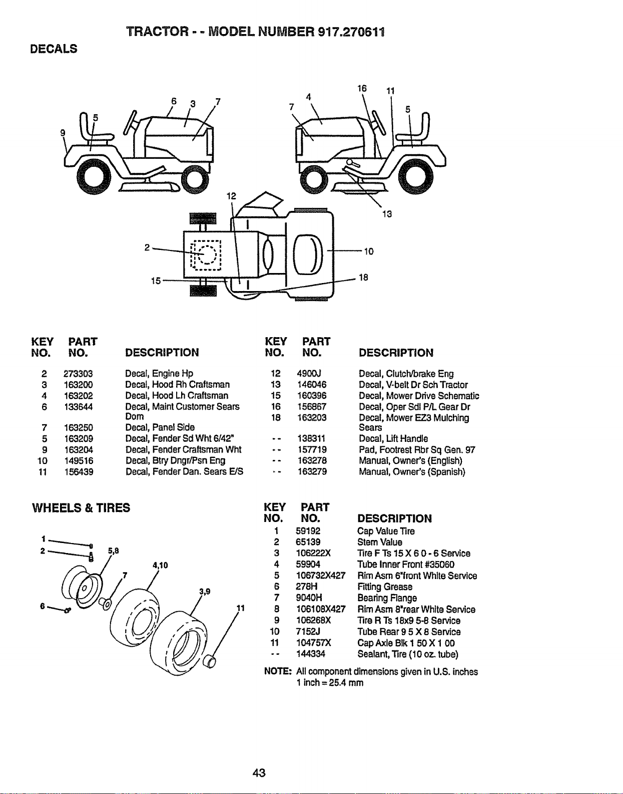
DECALS
TRACTOR =- MODEL NUMBER 917.270611
6 3 7 7 4
16
11
i2
13
KEY
NO.
2
3
4
6
PART
NO.
2_303
1632_
1632_
i_644
7 163250
5 163209
9 163204
'tO 149516
tt 156439
DESCRIPTION
Decal,EngineHp
Decal,Hood Rh Craftsman
Decal,Hood LhCraftsman
Decal,MaintCustomerSears
Dora
Decal,Panel Side
Decal,FenderSd Wht6142"
Decal,FenderCraftsmanWht
Decal,BtryDngr/PsnEng
Decal,FenderDan. SearsFJS
KEY
NO.
12
13
15
16
18
==
PART
NO.
4900J
146046
160396
156867
163203
138311
157719
163278
163279
DESCRIPTION
Decal,Clutch/brake Eng
Decal, V-beltDr SchTractor
Decal,Mower DriveSchematic
Decal,Oper SdlP/L Gear Dr
Decal,MowerEZ3 Mulching
Sears
Decal,Uft Handle
Pad, FootrestRbrSq Gen.97
Manual,Owner's(English)
Manual,Owner's(Spanish)
WHEELS & TIRES
4,10
!,9
KEY
NO,
1
2
3
4
5
6
7
11 8
9
lO
11
NOTE:
PART
NO.
59192
65139
106222X
599O4
106732X427
276H
9040H
106108)(427
106268)(
7152J
104757X
144334
DESCRIPTION
Cap ValueTire
SternValue
Tire FTs 15X 6 0.6 Service
Tube InnerFront#35060
RimAsm6"frontWhtteService
FittingGrease
BearingRange
RimAsm6'rear WhiteService
Tire R Ts 18x9 5-8 Service
Tube Rear9 5 X 8 Service
CapAxleBik 1 50 X 1 00
Sealant,Tire (10 oz..tube)
AllcomponentdimensionsgiveninU.S. inches
1 inch= 25.4 mm
43
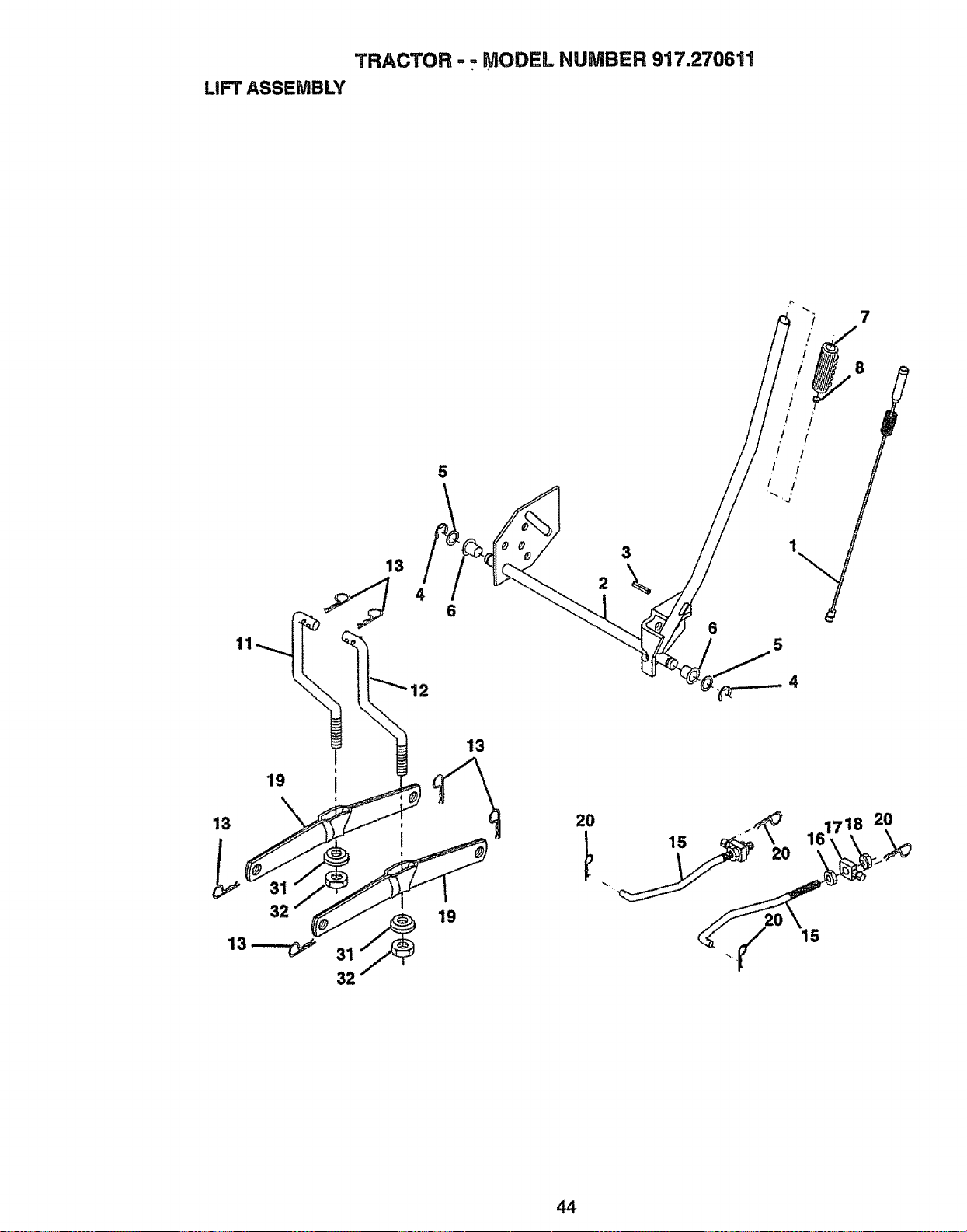
TRACTOR - = MODEL NUMBER 917.270611
LIFT ASSEMBLY
5
3
13
4
6
6
4
19
13
32
19
13
161718 20
15
44

TRACTOR-- MODEL NUMBER 917.270611
LiFT ASSEMBLY
KEY PART
NO. NO. DESCRIPTION
1 159460 WasherAsm InnerSpringW/Plunger
2 159471 ShaftAsmoUft
3 105767X PinGroove
4 12000002 E Ring #5133-62
5 19211621 Washer21132x 1 x 21 Ga_
6 120183X Bearing Nylong
7 125631X GripHandleRuted
8 122365X ButtonPlungerRead
11 139865 Link Asm Lift L.H,
12 139866 Link Asm Uft R_H.
13 STD624008 Retainer Spring
15 127218 Link Front
16 73350800 Nut Jam Hex 1/2.13 Unc
17 130171 TrunnionBIk Zinc
18 73800800 NutLock W/Wsh 1/2-13 Unc
19 139868 Arm SuspensionMower
20 STD624008 RetainerSpring
31 140302 Bearing, PvL Lift,Spherical
32 73540600 NutCrownlock3/8-24
NOTE:All componentdimensionsgiven inU.S. inches
1inch= 25,,4mm
45
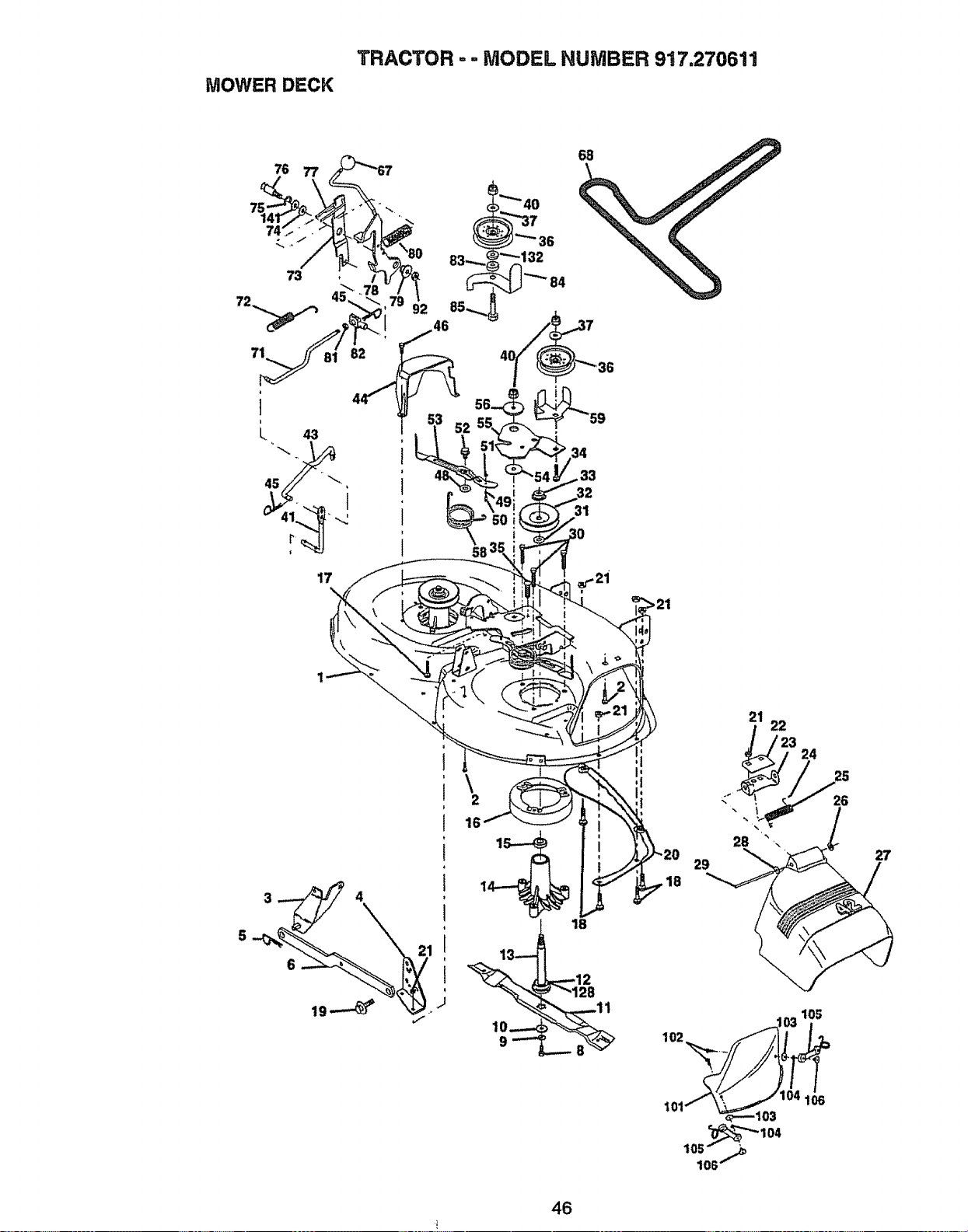
TRACTOR - - MODEL HUMBER 917.270611
MOWER DECK
17
\
33
31
\
2
16
18
29
21 22
_/_23 24
28 _,
102 _.
'_"_ 104
105
106
I06
27
46
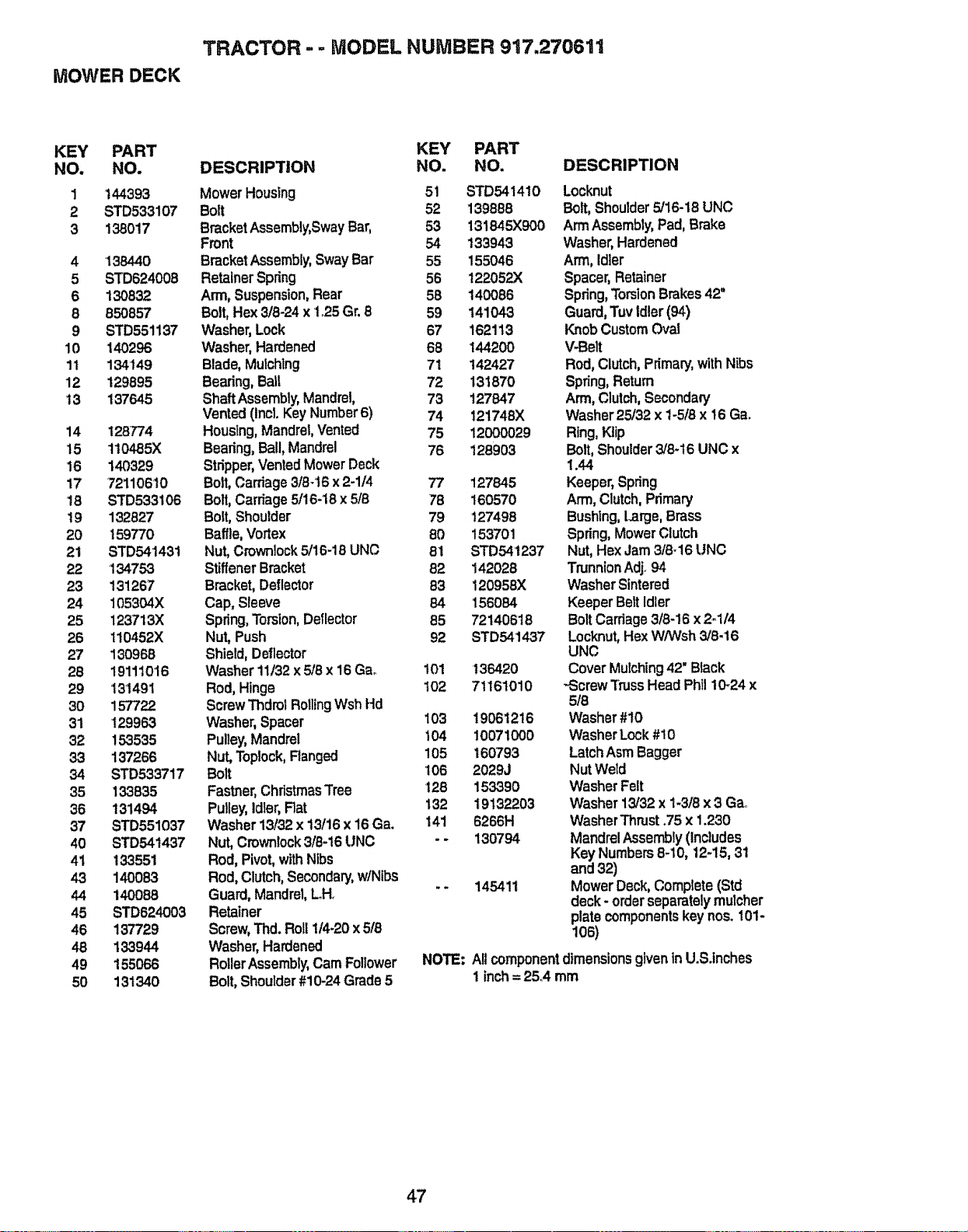
TRACTOR - - MODEL NUMBER 917,270611
MOWER DECK
KEY PART KEY PART
NO. NO. DESCRIPTION NO. NO.
1 144393 MowerHousing 51 STD541410
2 STD533107 Bolt 52 139888
3 138017 BracketAssembly,SwayBar, 53 131845X900
Front 54 133943
4 138440 BracketAssembly, SwayBar 55 155046
5 STD624008 Retainer Spring 56 122052X
6 130832 Arm, Suspension,Rear 58 140086
8 850857 Bolt,Hex 3/8-24 x to25 Gr.8 59 141043
9 STD551137 Washer,Lock 67 162113
10 140296 Washer,Hardened 68 144200
1t 134149 Blade,Mulching 71 142427
12 129895 Bearing,Ball 72 131870
t3 137645 ShaftAssembly,Mandrel, 73 127647
Vented(Incl.KeyNumber6) 74 121748X
14 128774 Houslng,Mandrel, Vented 75 12000029
t5 110485X Bearing,Ball, Mandrel 76 128903
16 140329 Stripper,'.,tentedMowerDeck
17 72110610 Bolt,Carriage318-16x 2-1/4 77 127845
18 STD533106 Bolt,Cardage5/t6-18 x 5/8 78 160570
19 132827 Bolt,Shoulder 79 127498
20 159770 Baffle,Vortex 80 153701
21 STD541431 Nut, Crownlock5/16-18UNC 81 STD541237
22 134753 StiffenerBracket 82 142028
23 131267 Bracket,Deflector 83 120958)(
24 105304X Cap, Sleeve 64 156084
25 1237t3X Spring,Torsion,Deflector 85 72140618
26 110452X Nut, Push 92 STD541437
27 130968 Shield,Deflector
28 191110'16 Washer11132x 5/8 x 16 Ga_ 101 136420
29 131491 Rod, Hinge 102 71161010
30 157722 ScrewThdrol RollingWsh Hd
31 129963 Washer, Spacer 103 t 9061216
32 153535 Pulley,Mandrel 104 10071000
33 137266 Nut, Toplock,Ranged 105 160793
34 STD533717 Bolt 106 2029J
35 133835 Fastner,ChristmasTree t28 153390
36 131494 Pulley, Idler,Rat 132 19132203
37 STD551037 Washer 13/32 x 13/16x 16 Ga. 141 6266H
40 STD541437 Nut, Crownlock3/8-16 UNC - - 130794
41 133551 Rod, Pivot, withNtbs
4.3 140083 Rod, Clutch,Secondary,wiNibs
44 140088 Guard, Mandrel,Loll. - * 145411
45 STD624003 Retainer
46 137729 Screw,Thd. Roll 11420x 5/8
48 133944 Washer, Hardened
49 155066 Roller Assembly,Cam Follower
50 131340 Bolt, Shoulder#10-24 Grade5
DESCRIPTION
Locknut
Bait, Shoulder5/16-18 UNC
Arm Assembly,Pad, Brake
Washer,Hardened
Arm, Idter
Spacer,Retainer
Spring,Torsion Brakes42"
Guard,Tuv Idler (94)
Knob Custom('Ycal
V-Belt
Rod,Clutch,Primary,withNibs
Spring,Return
Arm,Clutch,Secondary
Washer25/32 x 1-5t8x t6 Ga.
Ring,KJip
Bolt,Shoulder3/8-16 UNC x
1.44
Keeper,Spring
Arm,Clutch,Primary
Bushlng,Large,Brass
Spdng,MowerClutch
Nut,Hex Jam3/8-16 UNC
TrunnionAdj.94
WasherSintered
KeeperBeltIdler
BoltCarriage3t8-16x 2-.1/4
Locknut,Hex VV/Wsh3/8.16
UNC
CoverMulching42" Black
-ScrewTrussHeadPhi! 10-24x
5/8
Washer#10
Washer Lock#10
LatchAsmBagger
NutWeld
WasherFelt
Washer13132x 1-3/8 x3 Gao
WasherThrust.75 x 1.230
MandrelAssembly (Includes
Key Numbers8-10, 12-15,31
and 32)
MowerDeck,Complete(Std
deck - orderseparatelymutcher
platecomponentskeynos. 101-
106)
NOTE: A!lcomponent dimensionsgivenin U.S.inches
1 inch= 25°4 mm
47
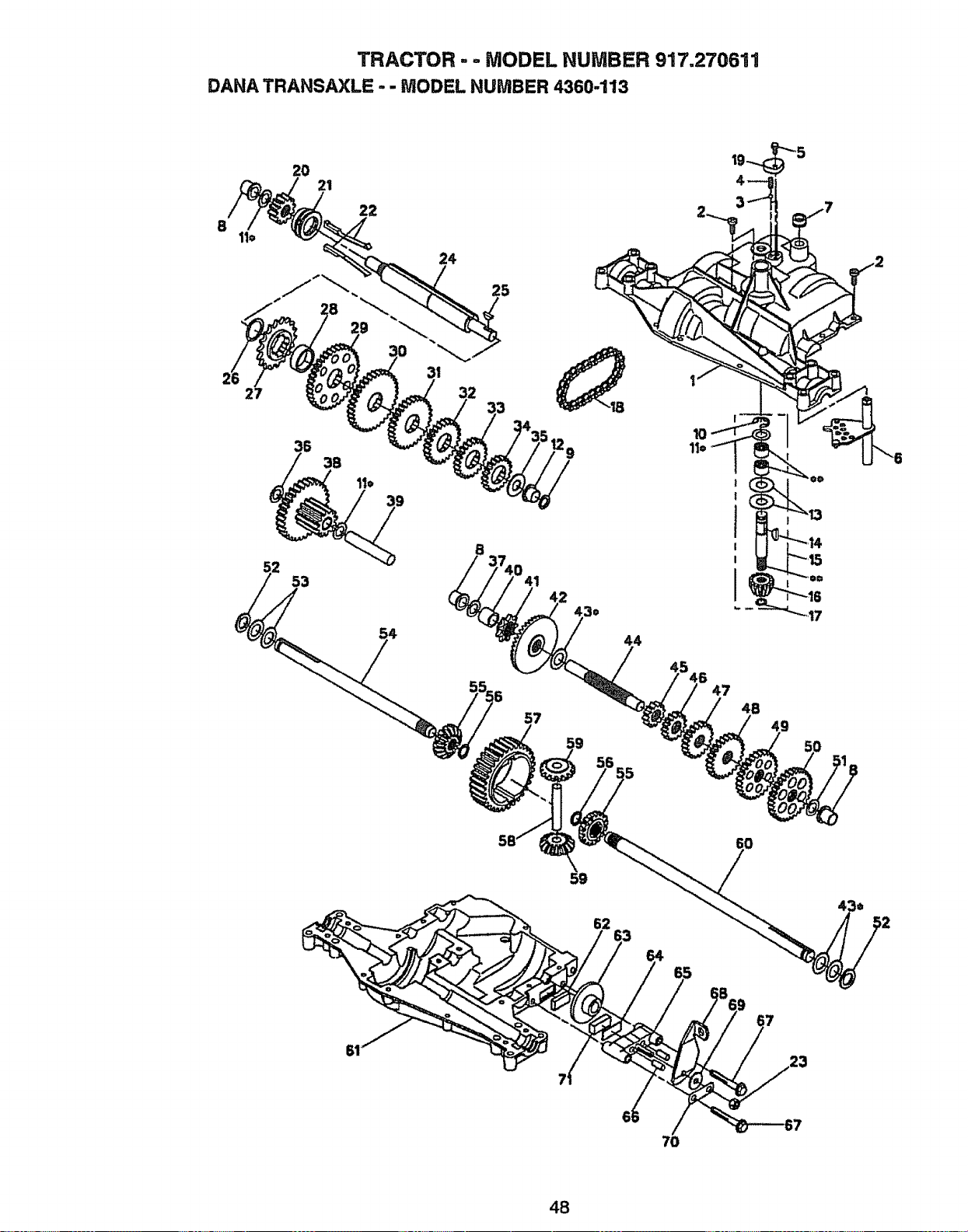
TRACTOR - - MODEL NUMBER 917,270611
DANA TRANSAXLE - - MODEL NUMBER 4360,.113
8
20
21
22
25
27
53
57
44
47
48
49
23
70
48
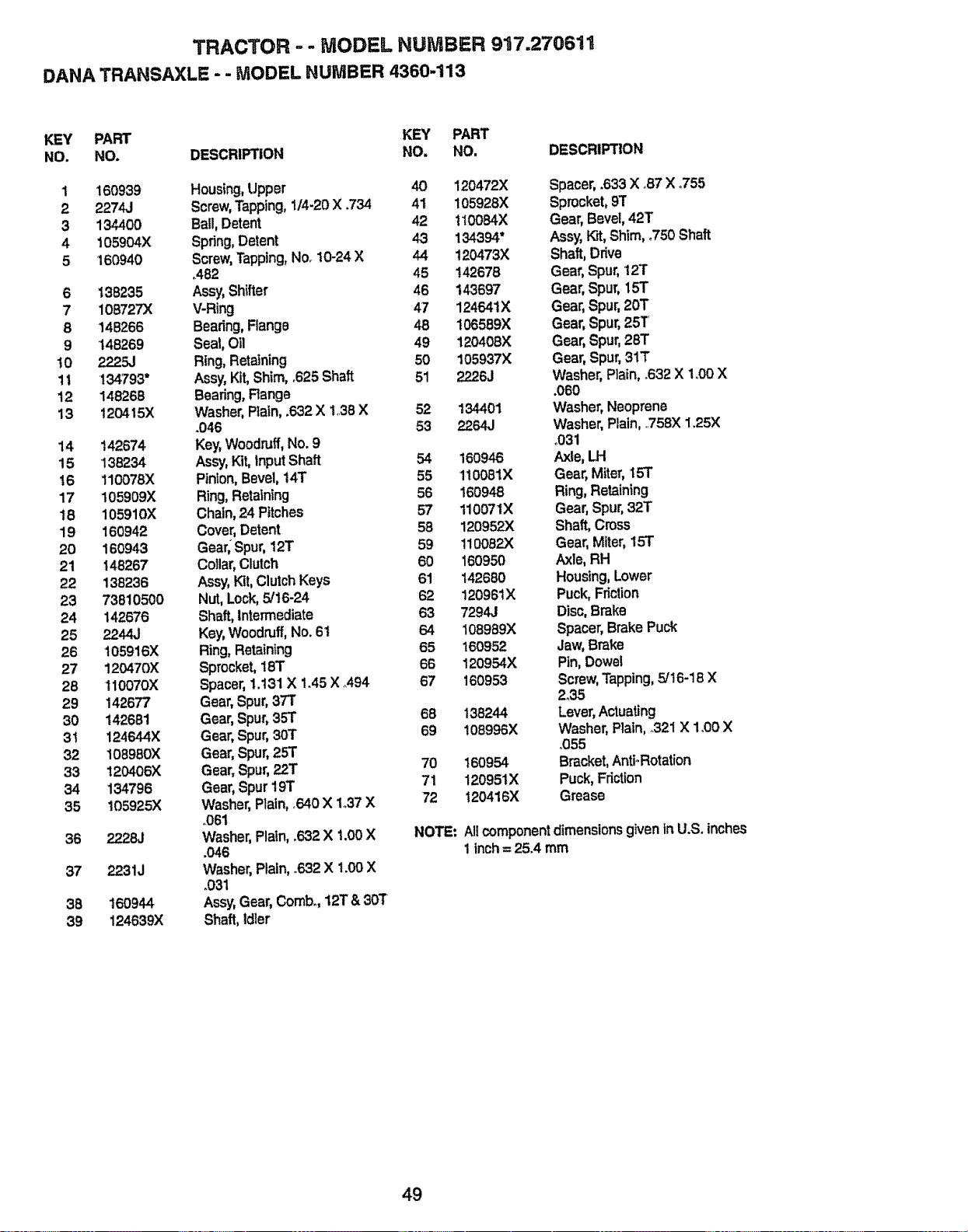
TRACTOR .... MODEL NUMBER 917.270611
DANA TRANSAXLE - . MODEL NUMBER 4:360-113
KEY PART KEY PART
NO. NO. DESCRIPTION NO. NO. DESCRIPTION
1 160939 Housing,Upper 40 120472X Spacer,.633 X °87X .755
2 2274J Screw,Tapping, 1/4-20X .734 41 105928)( Sprocket,91"
3 134400 Ball,Detent 42 110084X Gear,Bevel,42T
4 t05904X Spring,Detent 43 134394* Assy,Kit,Shim,_750Shaft
5 160940 Screw,Tapping,No. 10-24X 44 120473X Shaft, Drive
.482 45 142678 Gear,Spur,12T
6 138235 Assy,Shifter 46 143697 Gear,Spur, 15T
7 108727X V-Ring 47 124641X Gear, Spur,20T
8 148266 Beadng,Flange 48 !06589X Gear,Spur,25T
9 148269 Seal,Oil 49 120408X Gear, Spur,26T
!0 2225J Ring,Retaining 50 105937)( Gear, Spur,31T
11 134793" Assy,Kit,Shim, °625 Shaft 51 2226J Washer,Plain,.632 X 1°00X
12 148266 Bearing,Range .060
13 120415)( Washer, Plain,.632 X 138 X 52 134401 Washer, Neoprene
.046 53 2264J Washer,Plain,758X 1.25X
14 142674 Key,Woodruff, No.9 .031
15 136234 Assy,Kit,InputShaft 54 160946 Axle,LH
16 110078)( Pinion,Bevel,14T 55 110081X Gear, Miter,15T
17 105909X Ring,Retaining 56 160948 Ring,Retaining
t8 105910X Chain,24 Pitches 57 110071X Gear, Spur,32T
19 160942 Cover,Detent 58 120952X Shaft,Cross
20 160943 Gear,Spur, t2T 59 110062)( Gear, Miter,15T
21 148267 Cotlar,Clutch 60 160950 Axle,RH
22 138236 Assy,Kit,ClutchKeys 61 142680 Housing,Lower
23 73810500 Nut,Lock,5/16-24 62 12096tX Puck,Friction
24 142676 Shaft,Intermediate 63 7294.1 Disc,Brake
25 2244J Key,Woodruff,No. 61 64 108989)< Spacer,BrakePuck
26 105916X Ring,Retaining 65 160952 Jaw,Brake
27 120470)( Sprocket, 183" 66 120954X Pin,Dowel
28 110070X Spacer'1.131X 1.45X A94 67 160953 Screw,Tapping,5/t6-18 X
29 142677 Gear, Spur,37T 2.35
30 142681 Gear, Spur,35T 68 138244 Lever,Actuating
31 124644X Gear, Spur,30T 69 108996X Washer, Rain, .321 X 1.00 X
32 108980)( Gear, Spur,25T °055
33 120406X Gear, Spur,_T 70 160954 Bracket,Anti-Rotation
34 134796 Gear, Spur19T 71 120951X Puck, Friction
35 105925)< Washer,Plain,.640X 1o37X 72 120416)( Grease
.061
36 2228J Washer, Plain,.632 X 1.00X NOTE: Allcomponentdimensions givenin U.S. inches
.046 1 inch= 25.4 mm
37 22.31J Washer,Plain,.632 X 1.00 X
.031
38 160944 Assy,Gear, Comb, 12T & 30t'
39 124639X Shaft, Idler
49
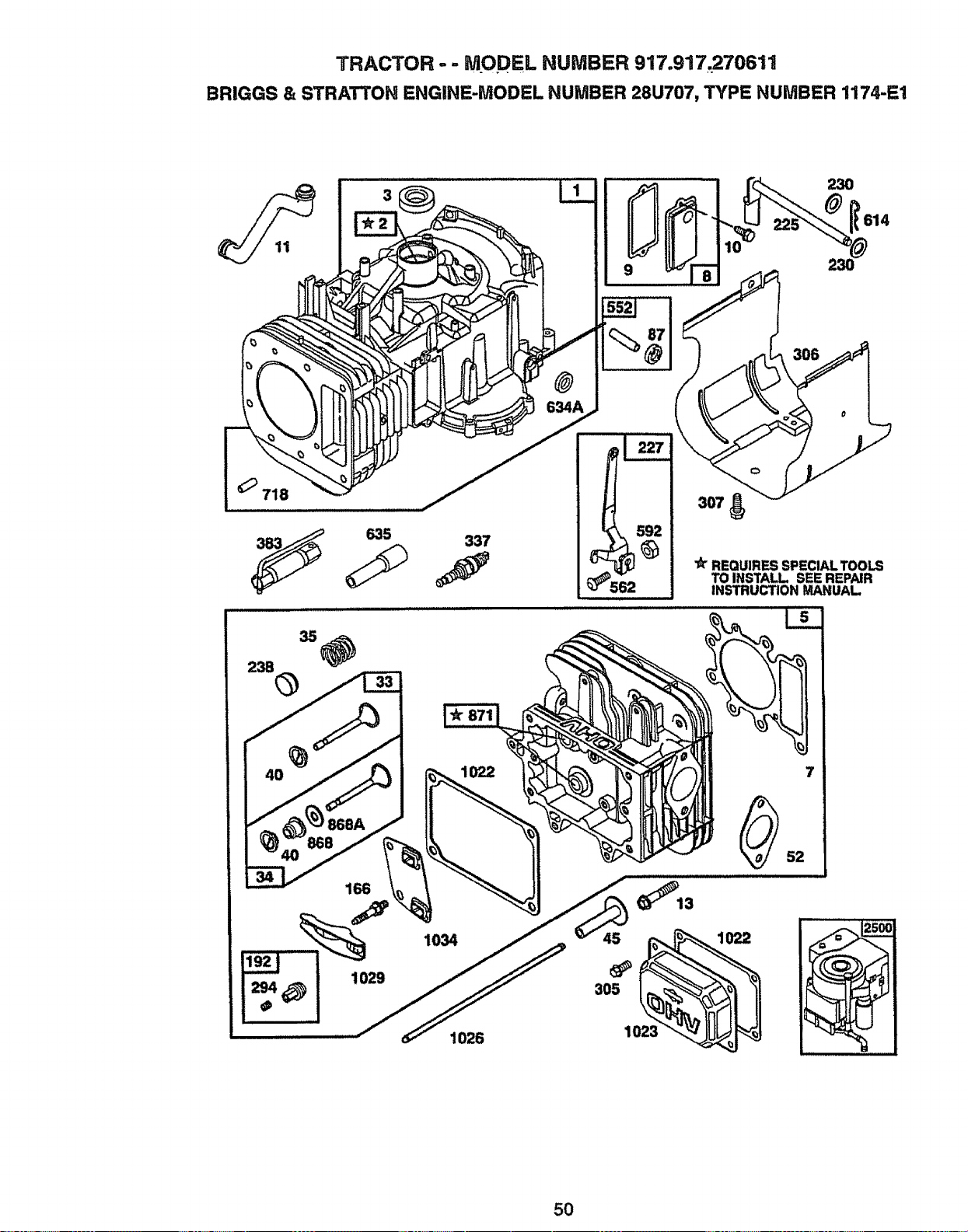
TRACTOR - - MODEL NUMBER 917.917,270611
BRIGGS & STRATTOH ENGINE-MODEL NUMBER 28U707, TYPE NUMBER 1174-E1
230
614
718
635 337
562
REQUIRES SPECIAL TOOLS
TO INSTALL SEE REPAIR
INSTRUCTION MANUAL
4O 1022 7
86
166
1029
1034
1026
1022
52
5O
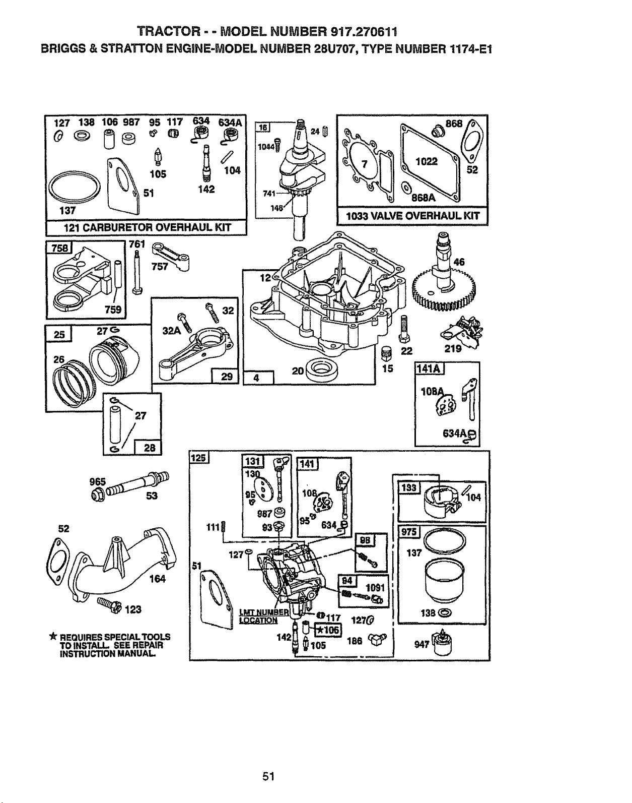
TRACTOR-- MODEL NUMBER 917.270611
BRIGGS & STRATTON ENGINE-MODEL NUMBER 28U707, TYPE NUMBER 1174-E1
127'_' "'"' ...............138 106/ 987 :_ 95 117 _.,_._ _4AIIIII"I,J, i
51 142
137
121 CARBURETOR OVERHAUL KIT
32
27_
3
lit REQUIRES SPECIALTOOLS
TO INSTALL SEE REPAIR
INSTRUCTION MANUAL.
2O
• 634A_
51
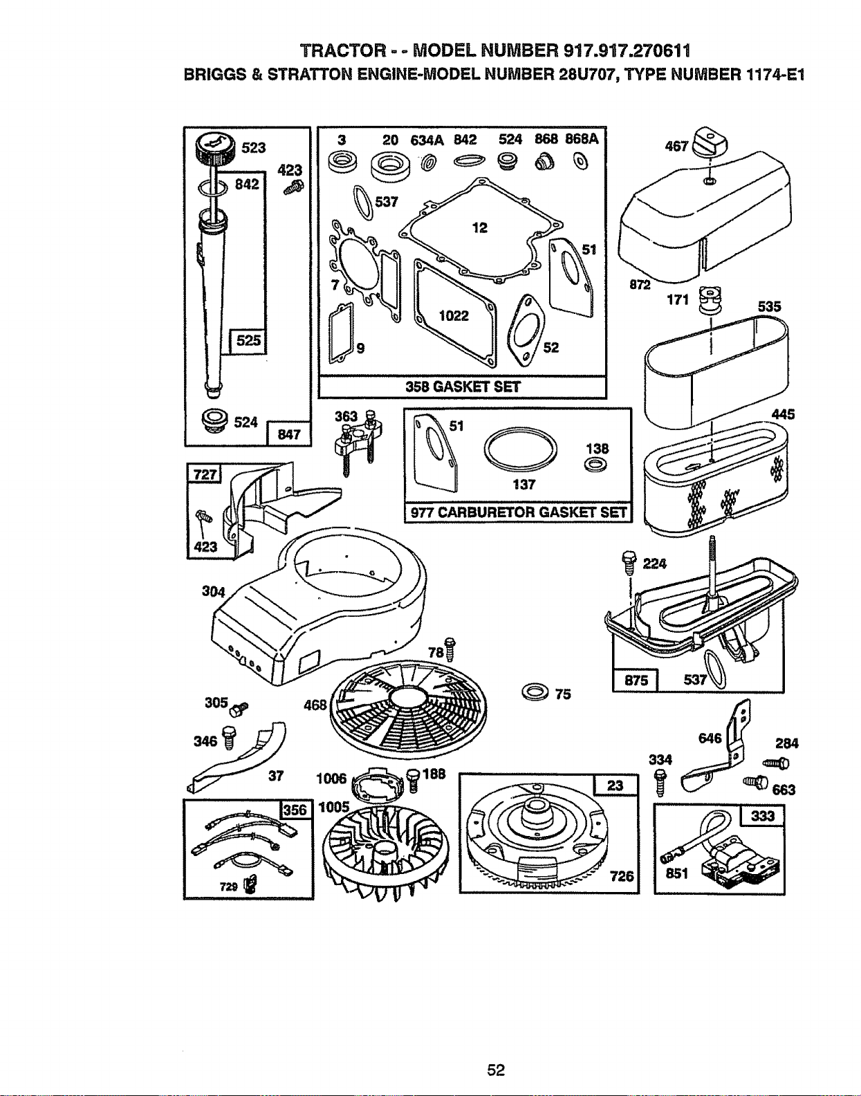
TRACTOR - ,. MODEL NUMBER 917.917.270611
BRIGGS & STRATTON ENGINE-MODEL NUMBER 28U707, TYPE NUMBER 1174-E1
,,,,,,,,,
3 20 634A 842 524 868 868A
358 GASKET SET
_524
1 138
137
977 CARBURETOR GASKET SET
171 _ 535
3O4
305_ 468
1006
(_ 75
646 284
334 _(D
52
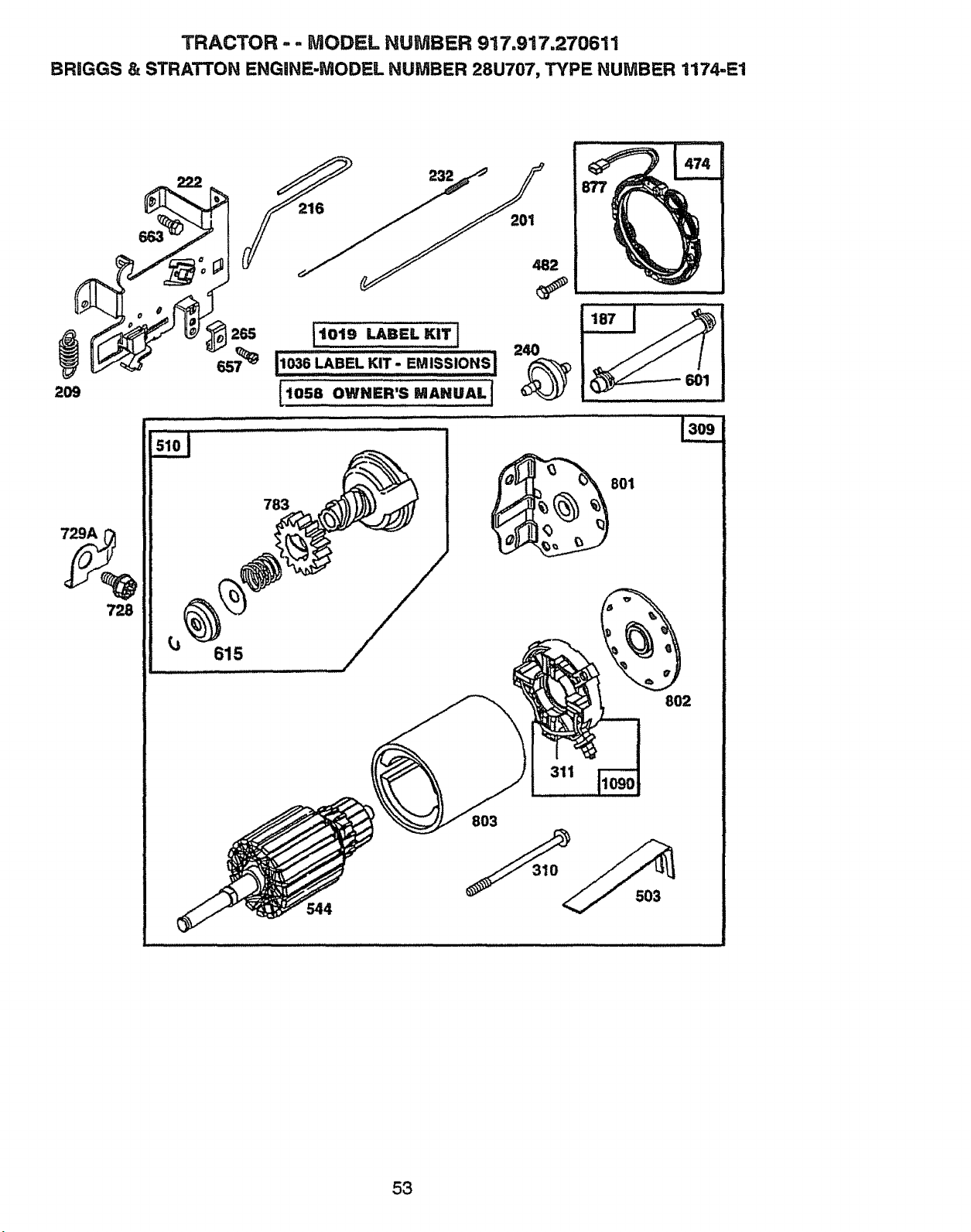
TRACTOR- .. MODEL NUMBER 917.917.270611
BRIGGS & STRATTON ENGINE-MODEL NUMBER 28U707, TYPE NUMBER 1174-E1
729A
615
783
801
802
311
544
8O3
503
53
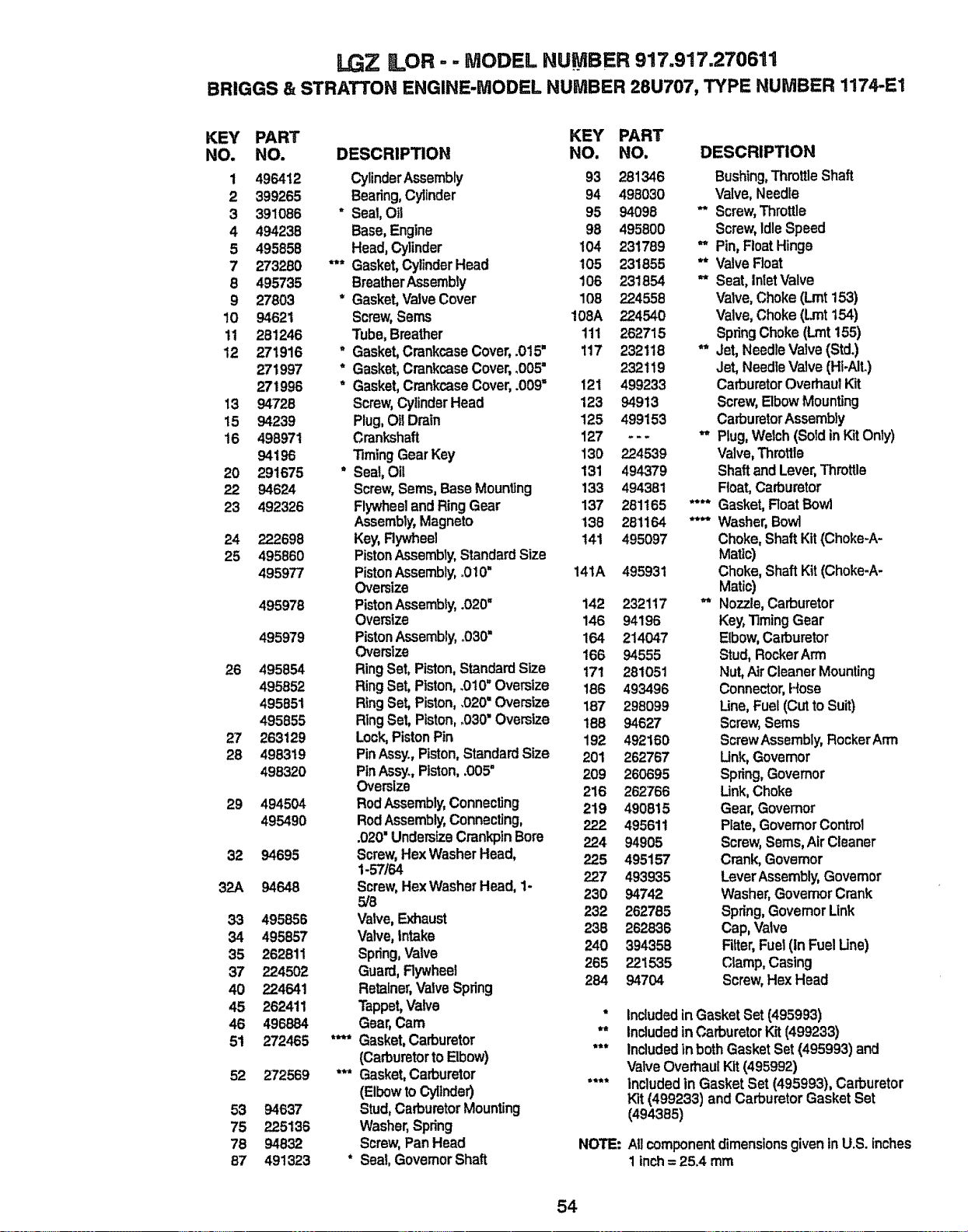
LGZ LOR - - MODEL NUMBER 917.917.270611
BRIGGS & STRATTON ENGINE.MODEL NUMBER 28U707, TYPE NUMBER 1174-E1
KEY PART KEY PART
NO. NO. DESCRIPTION NO. NO, DESCRIPTION
1 496412 CylinderAssembly 93 281346 Bushing,ThrottleShaft
2 399265 Beefing,Cylinder 94 498030 Valve,Needle
3 391086 * Seal,Oil 95 94098 ** Screw,Throttle
4 494238 Base,Engine 98 495800 Screw,idleSpeed
5 495858 Head,Cylinder 104 231789 *_ Pin,FloatHinge
7 273280 *'* Gasket,CylinderHead 105 231855 "* ValveFloat
8 495735 BreatherAssembly 106 231854 =* Seat, inletValve
9 27803 * Gasket,ValveCover 108 224558 Valve,Choke(Lmt153)
10 94621 Screw,Sems 108A 224540 Valve,Choke(Lmtt54)
11 281246 Tube,Breather 111 262715 SpringChoke (Lint155)
12 271916 * Gasket,CrankcaseCover,.015" 117 232118 ** Jet, NeedleValve(Std.)
271997 * Gasket,CrankcaseCover,.005" 232119 Jet, NeedleValve (HloAit.)
271996 * Gasket,CrankcaseCover,.009" 121 499233 CarburetorOverhaulKit
13 94728 Screw,CylinderHead 123 94913 Screw,ElbowMounting
15 94239 Plug,Oil Drain 125 499153 CarburetorAssembly
16 498971 Crankshaft 127 ... ,r, Plug,Welch(SoldinKit Only)
94196 TimingGear Key 130 224539 Valve,Throttle
20 291675 " Seal,Oil 131 494379 Shaftand Lever,Throttle
22 94624 Screw,Sems,BaseMounting 133 494381 Float,Carburetor
23 492326 Flywheeland RingGear 137 281165 **** Gasket,Roat Bowl
Assembly,Magneto 138 281164 **** Washer,Bowl
24 222698 Key, Rywheel 141 495097 Choke,ShaftKit (Choke-A-
25 495860 PistonAssembly,StandardSize Matlc)
495977 PistonAssembly, o010= 141A 495931 Choke, ShaftKit(Choke-A-
Oversize Matic)
495978 PistonAssembly,.020" 142 232117 ** Nozzle,Carburetor
Oversize 146 94196 Key,TimingGear
495979 PistonAssembly,o030" 164 214047 Elbow,Carburetor
Oversize 166 94555 Stud,RockerArm
26 495854 RingSet, Piston,StandardSize 171 281051 Nut,AirCleanerMounting
495852 RingSet, Piston,.010" Oversize 186 493496 Connector,Hose
495851 RingSet,Piston,.020"Oversize 187 298099 Line,Fuel(Cut to Suit)
495855 RlngSet, Piston,.030" Oversize 188 94627 Screw,Seres
27 263129 Lock,PistonPin 192 492160 ScrewAssembly,RockerArm
28 498319 PinAssyo,Piston,StandardSize 201 262767 Unk, Govemor
498320 PinAssy, Piston,.005" 209 260695 Spring,Governor
Oversize 216 262'766 Link,Choke
29 494504 RodAssembly,Connecting 219 490815 Gear,Governor
495490 RodAssembly,Connecting, 222 495611 Plate, GovernorControl
.020' UndersizeCrankpinBore 224 94905 Screw,Seres,Air Cleaner
32 94695 Screw,HexWasherHead, 225 495157 Crank,Governor
1-57/64 227 493935 LeverAssembly,Govemor
32A 94648 Screw,HexWasherHead, 1-
5/8 230 94742 Washer,GovemorCrank
33 495858 Valve,Exhaust 232 262785 Spring,GovernorUnk
34 495857 Valve,Intake 238 262836 Cap, Valve
35 262811 Spring,Valve 240 394358 Filter,Fuet (inFuel Une)
265 22! 535 Clamp,Casing
37 224502 Guard,Rywheal
40 224541 Retainer,Valve Spring 284 94704 Screw,Hex Head
45 262411 Tappet,Valve * Includedin Gasket Set (495993)
46 496884 Gear, Cam ** Included in CarburetorKit (499233)
5t 272465 *'!'* Gasket,Carburetor
(Carburetorto Elbow) "** Includedtn both Gasket Set (495993) and
Valve Overhaul Kit (495992)
52 272569 *** Gasket, Carburetor "*** Included in Gasket Set (495993), Carburetor
(Elbowto Cyflnder) Kit (499233) andCarburetorGasketSet
53 94637 Stud, CarburetorMounting (494385)
75 225t 36 Washer,Spring
76 94832 Screw,PanHead NOTE: At]componentdimensionsgiveninU.S. inches
87 49t323 * Seal, GovernorShaft 1inch= 25_4mm
54
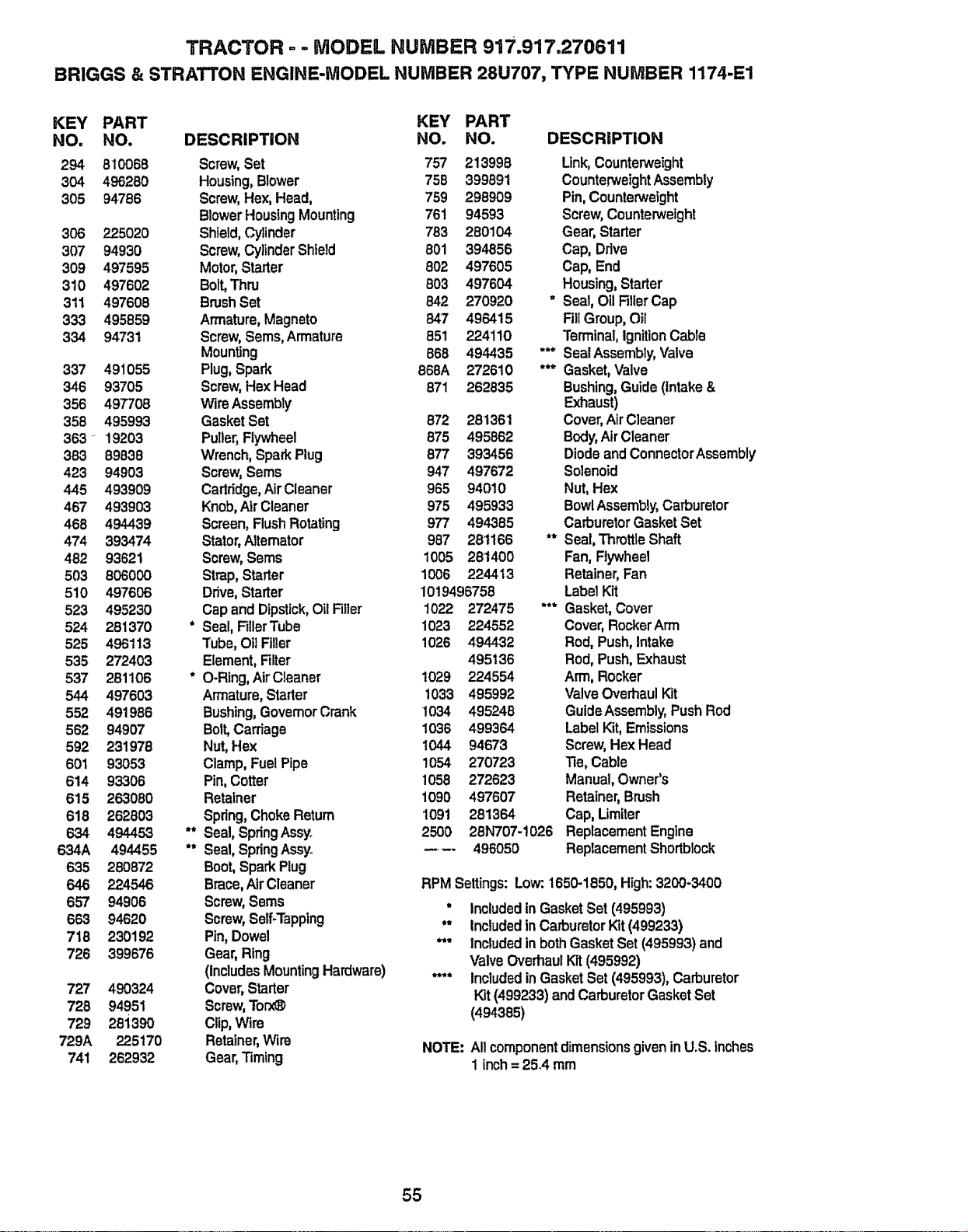
TRACTOR ,. - MODEL NUMBER 917.917.270611
BRIGGS & STRATTON ENGINE-MODEL NUMBER 28U707, TYPE NUMBER 1174-E1
KEY PART KEY PART
NO. NO. DESCRIPTION NO. NO. DESCRIPTION
294 810068 Screw,Set 757 213999 Link,Counterweight
304 496280 Housing,Blower 758 399891 CounterweightAssembly
305 94786 Screw,Hex, Head, 759 298909 Pin,Counterweight
BlowerHousingMounting 761 94593 Screw,Counterweight
306 225020 Shield,Cylinder 783 280104 Gear, Starter
307 94930 Screw,CylinderShield 801 394856 Cap, Drive
309 497595 Motor,Starter 802 497605 Cap, End
310 497602 Bolt,Thru 603 497604 Housing,Starter
311 497608 BrushSet 842 270920 = Seal, O11Filler Cap
333 495859 Armature,Magneto 847 496415 FillGroup,Oil
334 94731 Screw,Seres,Armature 85t 224110 Terminal,IgnitionCable
Mounting 668 494435 "** SealAssembly,Valve
337 491055 Plug,Spark 868A 272610 *** Gasket,Valve
346 93705 Screw,Hex Head 871 262835 Bushing,Guide(intake&
356 497708 Wire Assembly Exhaust)
358 495993 GasketSet 872 281361 Cover,AirC]eaner
363 _ 19203 Puller, Flywheel 875 495862 Body,AirCleaner
383 89838 Wrench,SparkPlug 877 393456 Diode andConnectorAssembly
423 94903 Screw,Sems 947 497672 Solenoid
445 493909 Cartridge,AirCleaner 965 94010 Nut, Hex
467 493903 Knob,AirCleaner 975 495933 BowlAssembly,Carburetor
468 494439 Screen,Flush Rotating 977 494385 Carburetor GasketSet
474 393474 Stator,Aitemator 987 28t166 *" Seal,ThrottleShaft
482 93621 Screw, Seres 1005 281400 Fan, Rywheet
503 806000 Strap, Starter 1006 224413 Retainer,Fan
510 497606 Drive, Starter 1019496758 Label Kit
523 495230 Cap and Dipstick,Oil Filler 1022 272475 *** Gasket, Cover
524 281370 * Seal,FillerTube 1023 224552 Cover, RockerArm
525 496113 Tube, Oil Filler 1026 494432 Rod, Push, Intake
535 272403 Element, Filter 495136 Rod, Push, Exhaust
537 281106 * O-Ring,AirCleaner 1029 224554 Arm, Rocker
544 497603 Armature, Starter 1033 495992 ValveOverhaul Kit
552 491986 Bushing,Govemor Crank 1034 495248 Guide Assembly, Push Rod
562 94907 Bott,Carriage 1036 499364 Label Kit, Emissions
592 231978 Nut, Hex 1044 94673 Screw,Hex Head
601 93053 Clamp, FuelPipe 1054 270723 Tie,Cable
614 93306 Pin,Cotter 1058 272623 Manual,Owner's
615 263080 Retainer 1090 497607 Retainer,Brush
618 262803 Spring,ChokeReturn 1091 281364 Cap, Limiter
634 494453 ** Seal,SpringAssy 2500 28N707-1026 Replacement Engine
634A 494455 ** Seal, SpringAssy, ---- 496050 Replacement Shortblock
635 260872 Boot,SparkPlug
646 224546 Brace,AirCleaner RPM Settings:Low:1650-1850, High:3200-3400
657 94906 Screw,Seres ° Includedin GasketSet (495993)
663 94620 Screw,Self-Tapping ** IncludedinCarburetorKit (499233)
718 230192 Pin, Dowel *** Includedin bothGasketSet (495993)and
726 399676 Gear, Ring Valve OverhaulKit(495992)
(IncludesMountingHardware) "*** Includedin GasketSet (495993),Carburetor
727 490324 Cover,Starter Kit(499233) and CarburetorGasketSet
726 94951 Screw,Torx_ (494385)
729 28i 390 Clip,Wire
729A 225170 Retainer,Wire NOTE: Allcomponentdimensions giveninU.S. Inches
741 262932 Gear,Timing 1 inch= 25.4 mm
55

56
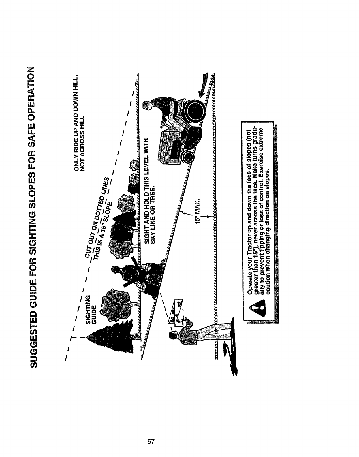
0
m
F=
<
0
ILl
<
0
l.U
0
,,,J
l/)
0
X
m
I,,-
I
0
IJ,l
Q
u
0
Q
W
I--
0
0
/
I
_i
,,,,I
m
=
Z
0
Q
Qj
Z_
<:_
NI=
Oz
I
/
0
I
I
I
I
I
I
I
I
I
/
/
I
<
o _
57

58

59

For the repair or replacementparts you need
delivered directly to your home '
Call 7 am - 7 pro, 7 days a week'.
1=800=366=PART
(1-800-366.7278)
Para ordenar piezas con entrega a
domicilio - 1-800-659-7084
For in-house major brand repair service
Call 24 hours a day, 7 days a week
1=800-4=REPAIR
(1-800-473-7274)
Para pedir servicio de reparaci6n a
domicilio - 1-800-676-5811
For the locationof a Sears Parts and
Repair Center in your area
Call 24 hours a day, 7 days a week
1,-800-488-1222
For informationon purchasing a Sears
Maintenance Agreement or to inquire
about an existingAgreement
Call 9 am - 5 pm, Monday-Saturday
1-800-827-6655
When requestingservice or ordering
parts, always providethe following
information:
oProductType , Part Number
° Model Number o Part Descriptio_
163278 Rev. 3 2.7.98 KF.SW/JH,
Amenca's Repalr Specia_is ts
Printed in U.S.A.


