Loading ...
Loading ...
Loading ...
© 2021 United States Stove Company
5
ASSEMBLY & INSTALLATION
1. Uncrate and/or unpack the heater, removing all
packing material, being careful not to dispose of the
parts bag.
2. Remove the following contents: (4) Legs with nut and
bolt package, (1) Lid, (1) Lid Lifter, (1) Shaker Grate,
(1) Ash Door, (1) Slide Draft, and (1) Feed Door.
3. Carefully lay the stove on its side, preferably on a soft
surface. Note: Cardboard shipping carton placed flat
works well for this application.
4. Securely attach all four (4) legs to the lower chamber
using nut and bolt package.
5. Carefully return the stove to the upright position and
place it in the desired location.
6. Place the lid in position on top of the plate.
7. Position ash door with slide draft on the front of the
lower chamber.
8. Place shaker grate in the lower chamber.
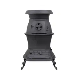
9. Place the heater on solid masonry, or solid concrete.
When the heater is used on a combustible floor, use
a listed floor protector. The floor protector must
comply with UL Standards. The base should extend
at least 18” beyond the door side of the heater and
should extend under the flue pipe (if it is elbowed
towards a wall). After observing the clearances to
combustibles, locate your floor protector accordingly,
and carefully place the stove in your selected
location. Install stovepipe, elbows, and thimble as
necessary, utilizing either a recently cleaned and
inspected masonry chimney or UL 103 HT Factory
Built Chimney, utilizing manufactures instructions.
39-1/2”
36”
42”
36”
18”
60” min
14-1/2” 10-1/4”
FLOOR
PROTECTOR
54”
3
6”
36”
Floor Protector
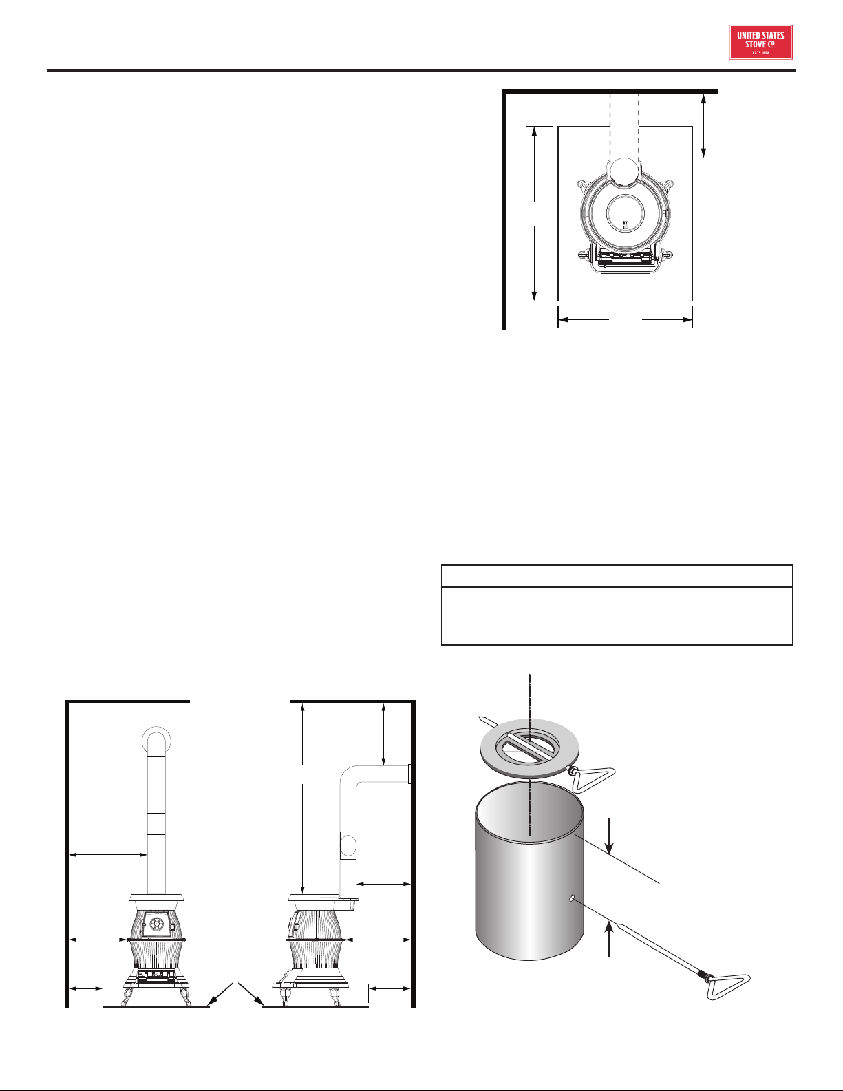
10. The flue pipe draft damper must be installed into
the top end of the first straight section of stove pipe
exiting the stove before the stove is used.
a. Drill two 1/4” holes centered on either side of
the pipe section 6” from the top end of the pipe
Remove the handle from the damper then slide
the damper into the pipe.
b. Align the damper with the holes drilled in step
8a and insert the handle through the holes and
the damper.
NOTE:
THIS DAMPER IS NECESSARY FOR THE PROPER
OPERATION OF THE STOVE. IT MUST BE INSTALLED
BEFORE USE (NO EXCEPTIONS)
6"/15.25 cm
Draft Damper
Installation
Loading ...
Loading ...
Loading ...