Loading ...
Loading ...
Loading ...
9
Installation
Box Heater until the Opti-myst
Cassette is installed. This will
help prevent scratches and
damage to the sides of the Opti-
myst Pro Box Heater.
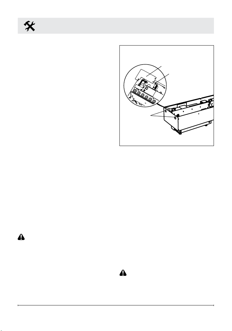
7. Follow the installation
instructions provided with the
Opti-myst Cassette to install
within the Opti-myst Pro Box
Heater. Use the provided
screws to fasten the cassette to
the Opti-myst Pro Box Heater
through the holes in the cassette
(Figure 3).
8. In the back left corner of the
Opti-myst Cassette (Figure 3),
locate and remove the electrical
cover plate by removing the two
securing screws.
9. Install a cable connector (not
included) suitable for mounting
in a ⅞ in. (22 mm) hole, to the
cable plate and feed the supply
cable through the connector.
The cable plate can be removed
by removing the two securing
screws on either side, to allow
for easier access.
CAUTION: Use two conductor,
non-metallic sheath cable with
ground wire (3 wires total) for the
incoming power supply on the
cassette. Use appropriate wire to
meet local and national electrical
codes for rated power.
10. Connect the black wires (live)
from the Opti-myst Cassette and
Opti-myst Pro Box Heater to the
live from the power supply.
11. Connect the white wires
(neutral) from the Opti-myst
Cassette and Opti-myst Pro Box
Heater to the neutral wire from
the power supply.
12. Connect the green wires
(ground) from the Opti-myst
Cassette and Opti-myst Pro Box
Heater to the ground wire from
the power supply.
13. Place all connectors inside the
Opti-myst Cassette and secure
the cable clamp to unit, making
sure that the cable clamp grips
only the jacket of service cable.
CAUTION: Ensure the wire
connectors are securely tightened,
so no bare wires (live or neutral) are
exposed.
Figure 3
Cable Plate
Electrical Cover Plate
Holes for
securing to
framing
Loading ...
Loading ...
Loading ...