Loading ...
Loading ...
Loading ...
.
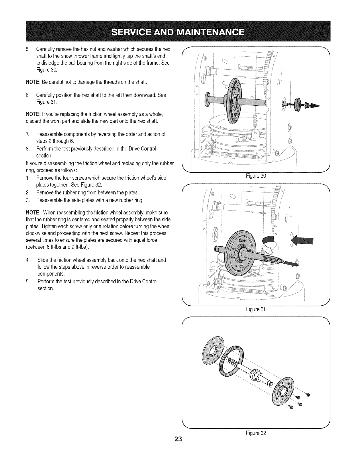
Carefullyremovethe hexnut andwasherwhichsecuresthehex
shaftto the snowthrowerframeand lightlytap the shaft'send
to dislodgethe ballbearingfromthe rightsideof the frame.See
Figure30.
NOTE:Becarefulnot to damagethe threadson the shaft.
6. Carefullypositionthe hex shaftto the left then downward.See
Figure31.
NOTE: If you'rereplacingthe frictionwheelassemblyas a whole,
discardthe wornpartand slidethe newpart ontothe hexshaft.
7. Reassemblecomponentsby reversingthe order and actionof
steps2 through6.
8. Performthe test previouslydescribedinthe DriveControl
section.
If you'redisassemblingthefrictionwheeland replacingonly the rubber
ring,proceedas follows:
1. Removethefour screwswhichsecurethe frictionwheel'sside
platestogether. SeeFigure32.
2. Removethe rubberring from betweenthe plates.
3. Reassemblethe side plateswith a newrubberring.
NOTE: Whenreassemblingthe frictionwheelassembly,makesure
thatthe rubberring is centeredand seatedproperlybetweenthe side
plates.Tighteneachscrewonlyone rotationbeforeturningthe wheel
clockwiseand proceedingwiththe nextscrew.Repeatthisprocess
severaltimes toensurethe platesare securedwith equalforce
(between6 ft-lbsand 9 ft-lbs).
4. Slidethe frictionwheelassemblybackonto the hexshaftand
followthestepsabovein reverseorderto reassemble
components.
5. Performthe testpreviouslydescribedin the DriveControl
section.
f
!
!
Figure30
Figure31
J
23
Figure32
.J
Loading ...
Loading ...
Loading ...