
Loading ...
Loading ...
Loading ...
• Holdadjustmentnutinpositionwithwrench
and tighten jam nut securely against ad-
justment nut.
TO REPLACE MOWER DRIVE BELT
MOWER DRIVE BELT REMOVAL
1. Park tractor on a level surface. Engage
parking brake.
2. Lower attachment lift lever to its lowest
position.
3. Disengage belt tension rod (K) from
_l_OCk bracket (L).
CAUTION: Belttension rod is spring load-
ed. Have a firm grip on rod and release slowly.
®
\
4. Remove screws (P) from R.H. and L.H.
mandrel covers and remove covers (Q).
5. Remove any dirt or grass clippings which
may have accumulated around mandrels
and entire upper deck surface.
6. Remove belt from electric clutch pulley
(M), both mandrel pulleys (R) and all idler
pulleys (S).
MOWER DRIVE BELT INSTALLATION
1. Install belt around both mandrel pulleys
(R) and around idler pulleys (S) as shown.
2. Install beltonto electric clutch pulley (M).
IMPORTANT: Check belt for proper routing
in all mower pulley grooves.
3. Reassemble R.H. and L.H. mandrel cov-
ers (Q). Securely tighten all screws.
4. Engage belt tension rod (K) on locking
bracket (L).
A&CAUTION: Belt tension rod is spring load-
ed. Have atightgrip on rod and engage slowly.
5. Raise attachment lift lever to highest
position.
TO ADJUST ATTACHMENT CLUTCH
The electric clutch should provide years of
service. The clutch has a built-in brake that
stopsthe pulleywithin 5 seconds. Eventually,
the internal brakewill wear which may cause
the mower bladesto notengage, or, to notstop
26
as required. Adjustments should be made
by a Sears or other qualified service center.
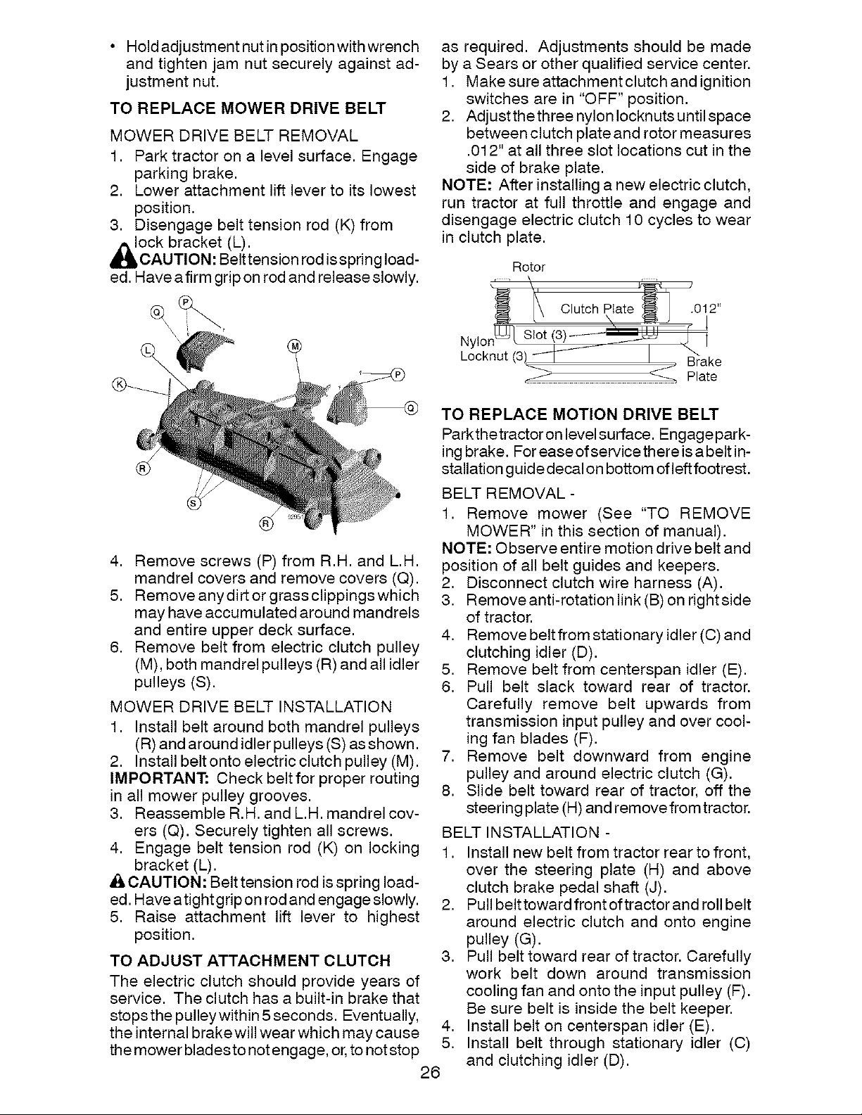
1. Make sure attachmentclutch and ignition
switches are in "OFF" position.
2. Adjust the three nylon Iocknuts until space
between clutch plate and rotor measures
.012" at all three slot locations cut in the
side of brake plate.
NOTE: After installing a new electric clutch,
run tractor at full throttle and engage and
disengage electric clutch 10 cycles to wear
in clutch plate.
Rotor
N,
Locknut (3
Brake
_ Plate
TO REPLACE MOTION DRIVE BELT
Parkthetractor on level surface. Engagepark-
ing brake. For easeofservicethereisabeltin-
stallation guide decal on bottom of left footrest.
BELT REMOVAL -
1. Remove mower (See "TO REMOVE
MOWER" in this section of manual).
NOTE: Observe entire motion drive belt and
position of all belt guides and keepers.
2. Disconnect clutch wire harness (A).
3. Remove anti-rotation link (B) on right side
of tractor.
4. Remove beltfrom stationary idler (C) and
clutching idler (D).
5. Remove belt from centerspan idler (E).
6. Pull belt slack toward rear of tractor.
Carefully remove belt upwards from
transmission input pulley and over cool-
ing fan blades (F).
7. Remove belt downward from engine
pulley and around electric clutch (G).
8. Slide belt toward rear of tractor, off the
steering plate (H) and remove from tractor.
BELT INSTALLATION -
1. Install new belt from tractor rear to front,
over the steering plate (H) and above
clutch brake pedal shaft (J).
2. Pull belt toward front of tractor and roll belt
around electric clutch and onto engine
pulley (G).
3. Pull belt toward rear of tractor. Carefully
work belt down around transmission
cooling fan and onto the input pulley (F).
Be sure belt is inside the belt keeper.
4. Install belt on centerspan idler (E).
5. Install belt through stationary idler (C)
and clutching idler (D).
Loading ...
Loading ...
Loading ...