Loading ...
Loading ...
Loading ...
1_ Loo_n Tne Qamplng _or_w'_ _wn_ mJ _tl _m _€;,nne'ls
• (item 2).
2. Adiust nuts(Item 3) by alternating loosening and tighten-
ing so that the channels are moved up or down an the
a_justing screws(Item 4) in the desired direction.
3. When channels are properly adjusted the arbor wrench
wifl just contact the table top when swung back and forth
at Positions 1, 2, 3, and 4 of Figure 9_ Tighten clamping
screws (Item 1). Recheck the four positionsto insure that
no change has occurred.
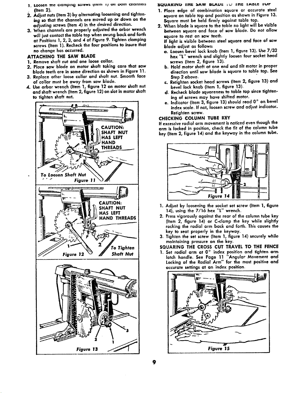
ATTACHING THE SAW BLADE
1. Remove shaft nut and one loose col|arm
2. Place saw blade on motor shaft taking care that saw
blade teeth are in some direction asshown in Figure 11_
3. Replace other loose coltar and shaft nut° Smooth face
of €ol|or must be away from saw blade.
,4. Use arbor wrench (item 1, figure 12 on motor shaft nut
and shaft wrench (Item 2, figure 12) on slot in motor shaft
to tighten shaft nut.
CAUTION:
SHAFT NUT
HAS LEFT
HAND
THREADS
To Loosen Shaft Nut
" ° "_ Figure 11
CAUTION:
SHAFT NUT
HAS LEFT
HAND THREADS
Figure 12
ro Tighten
Shaft Nut
2
Figure 13
:_IUAICII_ UM" :_AW ISI.AU= _ In" IAnLC lur
1. Place edge of combination square or accurate steel
square on table top and position as shown in Figure 13.
Square must be held firmly against table tap°
2. When blade is_uare to the table no light will be v_ible
between square and face of saw blade. Do not allow
square to rest on saw teeth.
If light is visible between steel square and face of sow
blade adjust as follows:
a. Loosenbevel lock knob (Item I, figure 13). Use 7/32
hex "L" wrench and sllghfly loosen four socket head
screws (item 2, figure 13).
b. Hold motor shaft at one end and tilt motor in proper
direction until saw blade is square to table top. See
Step 2 above_
c. Retlghten socket head screws (Item 2, figure 13) and
bevel lock knob (Item 1, figure 13).
d. Recheck blade _uareness to table top since tighten-
ing of screws may have shifted motor.
e. Indicator (item 3, figure 13) should read 0 ° on bevel
index scole_If not, loosen screw and adjust indicator.
Retlghten screw.
CHECKING COLUMN TUBE KEY
if excessiveradla| arm movement is noticed even though the
arm is locked in position, check the fit of the column tube
key (Item 2, figure 14) and the keyway in the column tube.
Figure 14
1. Adjust by loosening the socket set screw (Item I, figure
14), using the 7/16 hex "'L'" wrench°
2. Pressvigorously against the rear of the column tube key
(Item 2, figure 14) or C-clamp the key while slightly
rocking the radial arm back and forlh. This causes the
key to seat properly in the keyway°
3o Tighten the set screw (item 1, figure 1`4) securely whffe
maintaining pressure on the key°
SQUARING THE CROSS CUT TRAVEL TO THE FENCE
1_ Set radial arm at 0 ° index position and tighten arm
latch handle_ See Page 11 "Angular Movement and
Locking of the Radial Arm" for the most positive and
accurate sewings at an index Posilion,
Figure 15
9
Loading ...
Loading ...
Loading ...