Loading ...
Loading ...
Loading ...
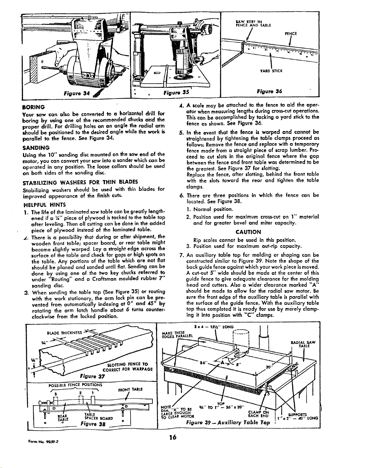
Figure 25
Figure 36
BOiUNG
Your saw can also be €onveded 1o a horZzonta| drill for
boring by using one of the recommended c_ucks ahd the
proper drill For drilling holes on an angle the radial arm
d_ould be positioned to the desired angle while the work is
parallel to the fence, See Figure34.
SANDING
Using the 10" sanding disc mounted on the saw end of the
motor, you can convert your saw into a sander which can be
operated in any position° The loose collars should be used
on both sides of the sanding disc°
STABILIZING WASHERS FOR THIN bLADES
Stabilizlng washers should be used with thin btades for
improved appearance of the finish cuts.
HELPFUL HINTS
1_ The life of the laminated saw table can be greatly length-
ened if a 1¼,,piece of plywood istacked to the table top
after leveling Then all cutting can be done in the added
plebe of plywood instead of the laminated table.
_. There is a posslbility that during or after shipment, the
wooden front tab|e; spacer board, or rear table might
became slightly warped Lay a straight edge across the
surface of the table and check for gaps or high spots on
the table. Any portions of the table which are not fiat
should be planed and sanded until flat Sanding can be
done by using one of the two key chucksreferred to
under "'Routing" and a Craftsman moulded rubber 7"
sanding disc_
2. When sanding the table top (See Figure 35) oI"routing
with the work stationary, the arm lock pln can be pre-
vented from automotlcally indexing at 0 ° and 45 ° by
rotating the arm latch handle about 6 turns counter-
clockwise from the locked position_
4. A scale may be attached to the fence to aid the oper-
at'or whenmeasuring lengths during cToss-cutoperations.
This can be accomplished by ta_ing a yard stick to the
fence as shown° See Figure 36_
S. In the event that the fence is warped and cannot be
straightened by tightening the table clamps proceed as
follows: Removethe fence and replace with a temporary
fence made from a straight piece of scrap lumber_ Pro-
ceed to cut slot_ in the original fence where the gap
between the fence and front table was determined to be
the greatest_ See Figure 37 for slotting.
Replace the fence, after slotting, behind the front table
with the dots toward the rear and tighten the tabte
damps_
6. There are three positions in which the fence can be
located. See Figure 38.
I. Normal position.
2. Position used for maximum cross-cut an 1" material
and for greater bevel and miter capacity°
CAUTION
Rip scales cannot be used in this F_>sltlon.
3_ Position used for maximum out-Hp capQcff',/.
7. An auxiliary table top for molding or shaping can be
constructed slmffar to Figure 39_ Note the shape of the
back guide fence against which your work p_eceis moved°
A cut-out 5" wide should be made at the center of this
guide fence to give adequate clearance for the molding
head and cutters. Also a wider clearance marked "'A°'
should be made to allow for the radial saw motor. Be
sure the front edge of the auxiliary table is parallel with
the surface of the guide fence. With the auxiliary table
top thus completed it is ready for use by merely damp-
lng it into position with "C °' clamps.
2_4 -- I,._A_°_ LONG
EDGES rA_LALLEL I I
! lAD IAL SAW
TABLE
Figure 37
_,_ _ 16