Installation Instructions
40MAQ
High Wall Ductless System
Sizes 09 to 36
NOTES:
Read the entire instruction manual before starting the
installation.
Images are for illustration purposes only. Actual models
may differ slightly.
TABLE OF CONTENTS
PAGE
SAFETY CONSIDERATIONS 2.........................
PARTS LIST 3.......................................
SYSTEM REQUIREMENTS 4...........................
WIRING 4...........................................
DIMENSIONS 5......................................
CLEARANCES 9.....................................
INSTALLATION TIPS 10...............................
INDOOR UNIT INSTALLATION 10......................
ELECTRICAL DATA 11...............................
CONNECTION DIAGRAMS 11.........................
FINAL TUBING CHECK 11............................
WIRELESS REMOTE CONTROL INSTALLATION 13......
WIRED REMOTE CONTROL INSTALLATION 13..........
START−UP 13........................................
TROUBLESHOOTING 14..............................
2
SAFETY CONSIDERATIONS
Installing, starting up, and servicing air−conditioning equipment
can be hazardous due to system pressures, electrical components,
and equipment location (roofs, elevated structures, etc.).
Only trained, qualified installers and service mechanics should
install, start−up, and service this equipment.
Untrained personnel can perform basic maintenance functions such
as coil cleaning. All other operations should be performed only by
trained service personnel.
When working on the equipment, observe precautions in the
literature and on tags, stickers, and labels attached to the
equipment.
Follow all safety codes. Wear safety glasses and work gloves. Keep
a quenching cloth and fire extinguisher nearby when brazing. Use
care in handling, rigging, and setting bulky equipment.
Read these instructions thoroughly and follow all warnings or
cautions included in the literature and attached to the unit. Consult
the local building codes and National Electrical Code (NEC) for
special requirements. Recognize safety information. This is the
safety−alert symbol
!
!
. When you see this symbol on the unit and
in instructions or manuals, be alert to the potential for personal
injury. Understand these signal words: DANGER, WARNING,
and CAUTION. These words are used with the safety−alert
symbol. DANGER identifies the most serious hazards which will
result in severe personal injury or death. WARNING signifies
hazards which could result in personal injury or death. CAUTION
is used to identify unsafe practices which may result in minor
personal injury or product and property damage. NOTE is used to
highlight suggestions which will result in enhanced installation,
reliability, or operation.
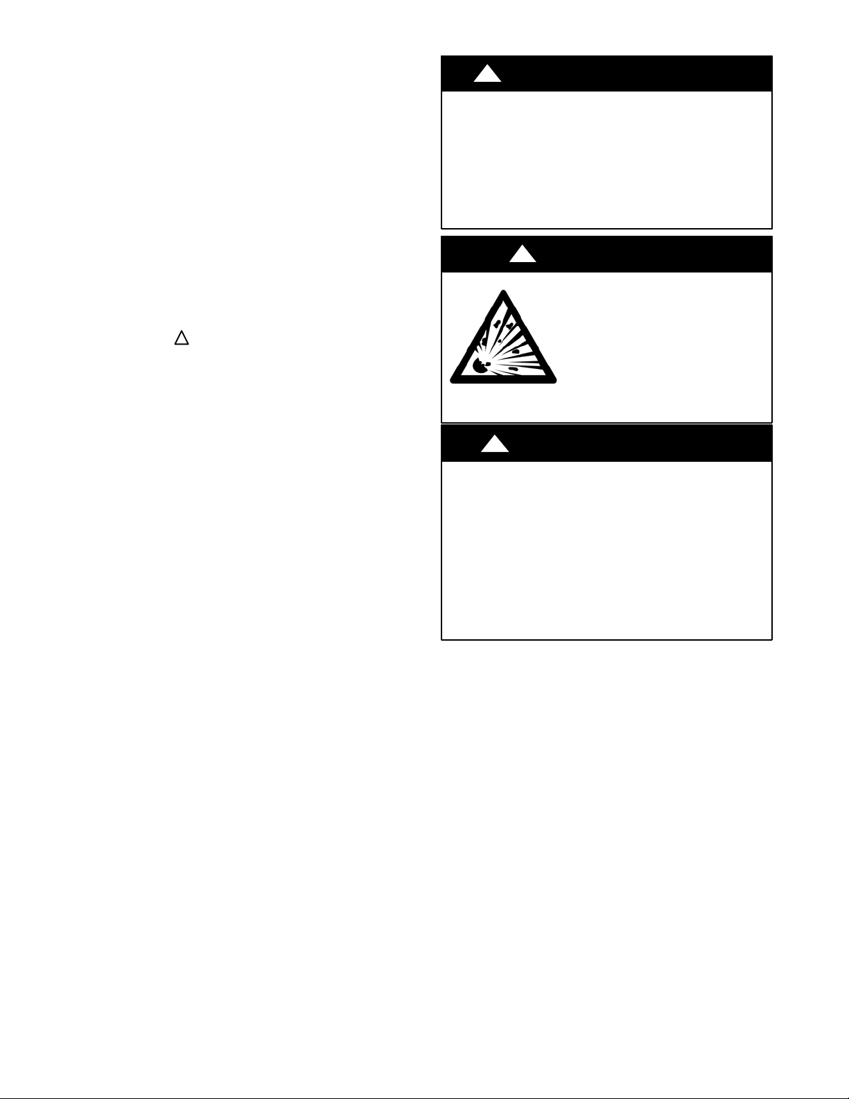
!
WARNING
ELECTRICAL SHOCK HAZARD
Failure to follow this warning could result in personal
injury or death.
Before installing, modifying, or servicing system, main
electrical disconnect switch must be in the OFF
position. There may be more than 1 disconnect switch.
Lock out and tag switch with a suitable warning label.
EXPLOSION HAZARD
Failure to follow this warning could
result in death, serious personal injury,
and/or property damage.
Never use air or gases containing
oxygen for leak testing or operating
refrigerant compressors. Pressurized
mixtures of air or gases containing
oxygen can lead to an explosion.
!
WARNING
CAUTION
!
EQUIPMENT DAMAGE HAZARD
Failure to follow this caution may result in equipment
damage or improper operation.
Do not bury more than 36 in. (914 mm) of refrigerant pipe
in the ground. If any section of pipe is buried, there must be
a 6 in. (152 mm) vertical rise to the valve connections on
the outdoor units. If more than the recommended length is
buried, refrigerant may migrate to the cooler buried section
during extended periods of system shutdown. This causes
refrigerant slugging and could possibly damage the
compressor at start−up.
3
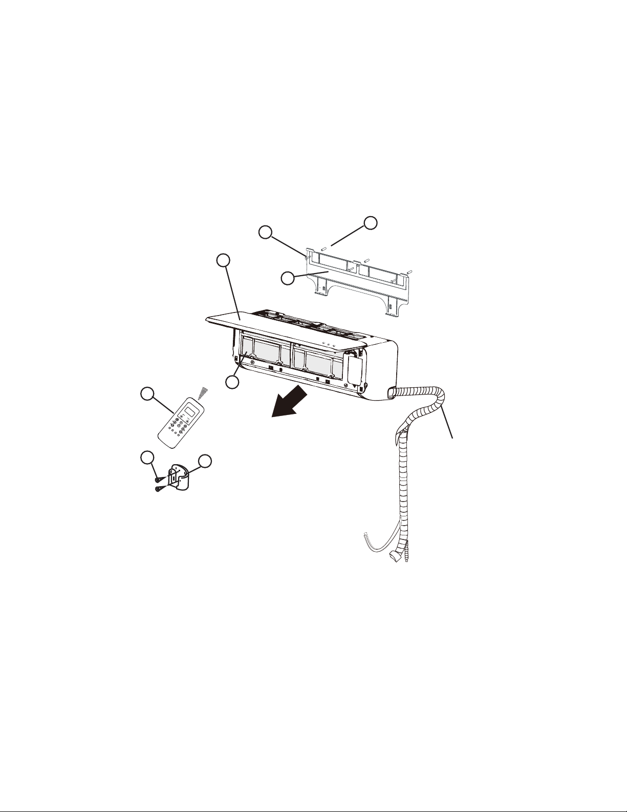
PARTS LIST
Table 1—Parts List
Part No.
Part Name
Qty
1
Indoor Unit
1
2
Mounting Plate
1
3
Mounting Screw A ST3.9x25-C-H
5
4
Anchor
5
5
Air Filter
1
6
Wireless Remote Control
1
7
Wireless Remote Control Holder
1
8
Wireless Remote Control Mounting Screw B ST2.0x10-C-H
2
- Flare nuts for liquid and gas pipes 1
- Stencil (Mounting Template) 1
- Installation Instructions 1
- Owner's manual 1
- Warranty Card 1
- Carbon Filter 1
Ai
r
Outlet
S
e
l
f
C
l
e
a
n
Fol
l
o
w
M
e
L
E
D
T
u
r
b
o
I
o
n
i
z
e
r
S
m
a
r
t
E
y
e
S
i
le
n
c
e
M
o
d
e
O
n
/
O
f
f
F
a
n
S
l
e
e
p
S
w
i
n
g
T
im
e
r
T
E
M
P
A
U
T
O
C
O
O
L
D
R
Y
H
E
A
T
F
A
N
H
I
G
H
M
E
D
L
O
W
F
.
P
.
1
5
6
8
7
2
3
4
Interconnecting
Piping/wiring
Fig. 1 - Parts List
Note:
- If the outdoor unit is higher than the indoor unit, prevent rain from flowing into the indoor unit along the connection pipe by making a inverted trap in the connection pipe before it enters
the wall to the indoor unit. This ensures that rain drips from the connection pipe before it enters the wall.
- Piping and the interconnecting wiring are field supplied.
- The illustration above is only a sketch. Different models may be slightly different.
The following units are covered in these installation instructions.
Table 2—Indoor Units
Description kBTUh V-Ph-Hz ID Model No.
High Wall Heat Pump
9 115-1-60 40MAQB09B--1
12 115-1-60 40MAQB12B--1
9 208/230-1-60 40MAQB09B--3
12 208/230-1-60 40MAQB12B--3
18 208/230-1-60 40MAQB18B--3
24 208/230-1-60 40MAQB24B--3
30 208/230-1-60 40MAQB30B--3
36 208/230-1-60 40MAQB36B--3

4
SYSTEM REQUIREMENTS
Allow sufficient space for airflow and unit service. See Fig. 6 for the minimum required distances between the unit and walls or ceilings.
Piping
IMPORTANT: Both refrigerant lines must be insulated separately.
S Table 3 lists the pipe sizes for the indoor unit. Refer to the outdoor unit’s installation instructions for other allowed piping lengths and
refrigerant information.
Table 3—Indoor Unit Pipe Sizes
UNIT SIZE
9K
(115V)
12K
(115V)
9K
(208/230V)
12K
(208/230V)
18K
(208/230V)
24K
(208/230V)
30K
(208/230V)
36K
(208/230V)
Gas Pipe
in 3/8 1/2 3/8 1/2 1/2 5/8 5/8 5/8
(mm) 9.52 12.7 9.52 12.7 12.7 16 16 16
Liquid Pipe
in 1/4 1/4 1/4 1/4 1/4 3/8 3/8 3/8
(mm) 6.35 6.35 6.35 6.35 6.35 9.52 9.52 9.52
WIRING
All wires must be sized per NEC (National Electrical Code) or
CEC (Canadian Electrical Code) and local codes. Use Electrical
Data table MCA (minimum circuit amps) and MOCP (maximum
over current protection) to correctly size the wires and the
disconnect fuse or breakers respectively.
Per the caution note, only stranded copper conductors with a 600
volt insulation rating wire must be used.
Recommended Connection Method for Power and
Communication Wiring:
The main power is supplied to the outdoor unit. The field supplied
14/3 stranded wire with ground with a 600 volt insulation rating,
power/communication wiring from the outdoor unit to indoor unit
consists of four (4) wires and provides the power for the indoor
unit. Two wires are line voltage AC power, one is communication
wiring (S) and the other is a ground wire. Wiring between indoor
and outdoor unit is polarity sensitive. The use of BX wire is NOT
recommended.
If installed in a high Electromagnetic field (EMF) area and
communication issues exists, a 14/2 stranded shielded wire can be
used to replace L2/N and (S) between outdoor unit and indoor unit
landing the shield onto ground in the outdoor unit only.
CAUTION
!
EQUIPMENT DAMAGE HAZARD
Failure to follow this caution may result in equipment
damage or improper operation.
Wires should be sized based on NEC or CEC and local
codes.
Use copper conductors only with a 600 volt insulation
rating wire.
CAUTION
!
EQUIPMENT DAMAGE HAZARD
Failure to follow this caution may result in equipment damage
or improper operation.
Be sure to comply with local codes while running wire from
the indoor unit to the outdoor unit.
Every wire must be connected firmly. Loose wiring may cause
the terminal to overheat or result in unit malfunction. A fire
hazard may also exist. Ensure all wiring is tightly connected.
No wire should touch the refrigerant tubing, compressor or
any moving parts.
Disconnecting means must be provided and shall be located
within sight and readily accessible from the air conditioner.
Connecting cable with conduit shall be routed through the
hole in the conduit panel.
5
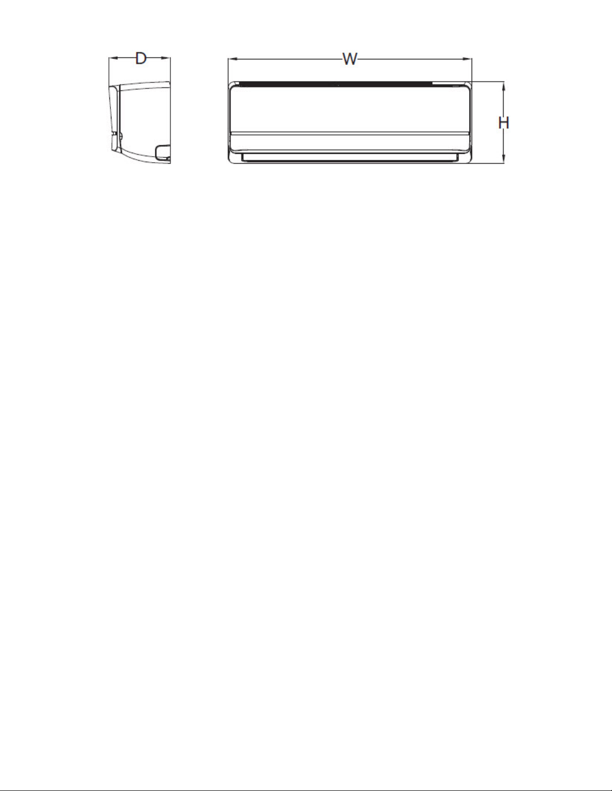
DIMENSIONS
Fig. 2 - Indoor Unit
Table 4—Dimensions
HIGH WALL UNIT SIZE 9K 12K 9K 12K 18K 24K 30K 36K
Voltage (115V) (115V) (208/230V) (208/230V) (208/230V) (208/230V) (208/230V) (208/230V)
Height In (mm) 11.07 (281) 11.07 (281) 11.07 (281) 11.07 (281) 12.40 (315) 13.39 (343) 13.39 (343) 13.39 (343)
Width In (mm) 33.17 (842) 33.17 (842) 33.17 (842) 33.17 (842) 38.98 (990) 46.69 (1186) 46.69 (1186) 46.69 (1186)
Depth In (mm) 8.75 (222) 8.75 (222) 8.75 (222) 8.75 (222) 8.58 (218) 10.16 (258) 10.16 (258) 10.16 (258)
Weight-Net Lbs (kg) 19.18 (8.7) 19.18 (8.7) 19.18 (8.7) 19.18 (8.7) 24.46 (12.0) 40.12 (18.2) 40.12 (18.2) 40.12 (18.2)
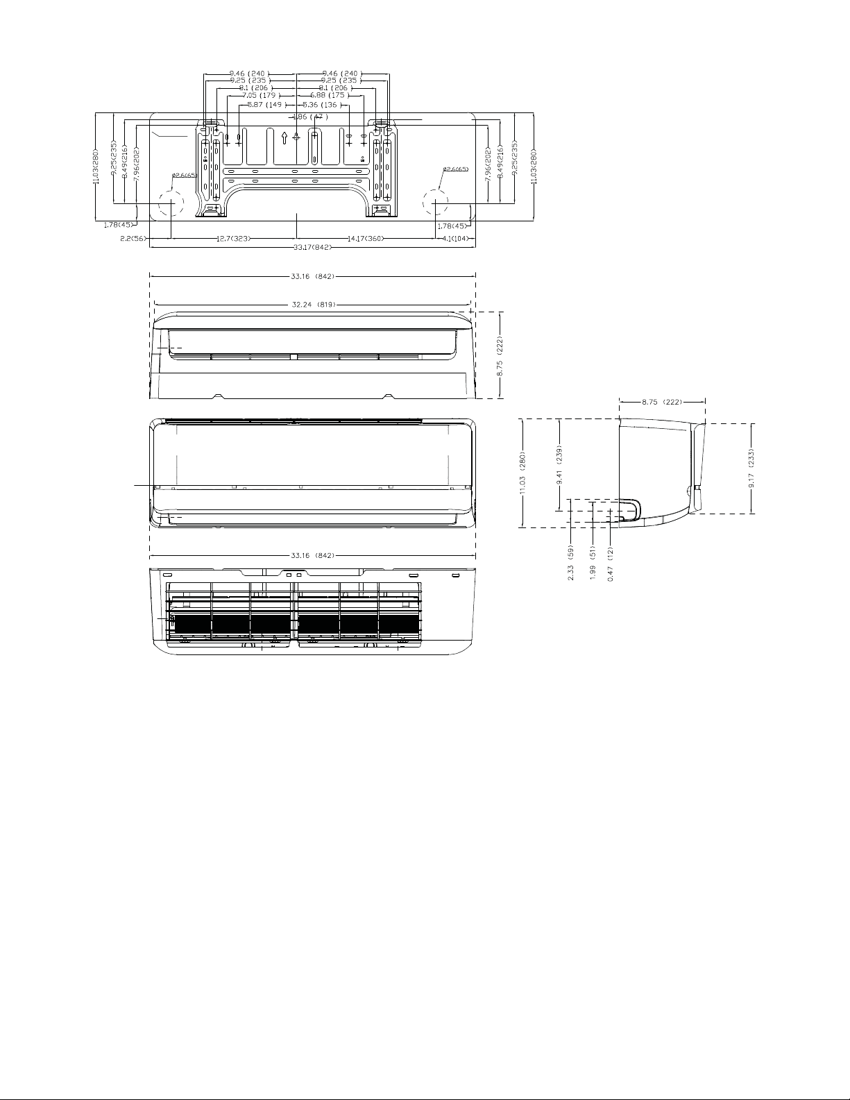
6
DIMENSIONS (CONT)
Indoor unit outline
Fig. 3 - 9K and 12K
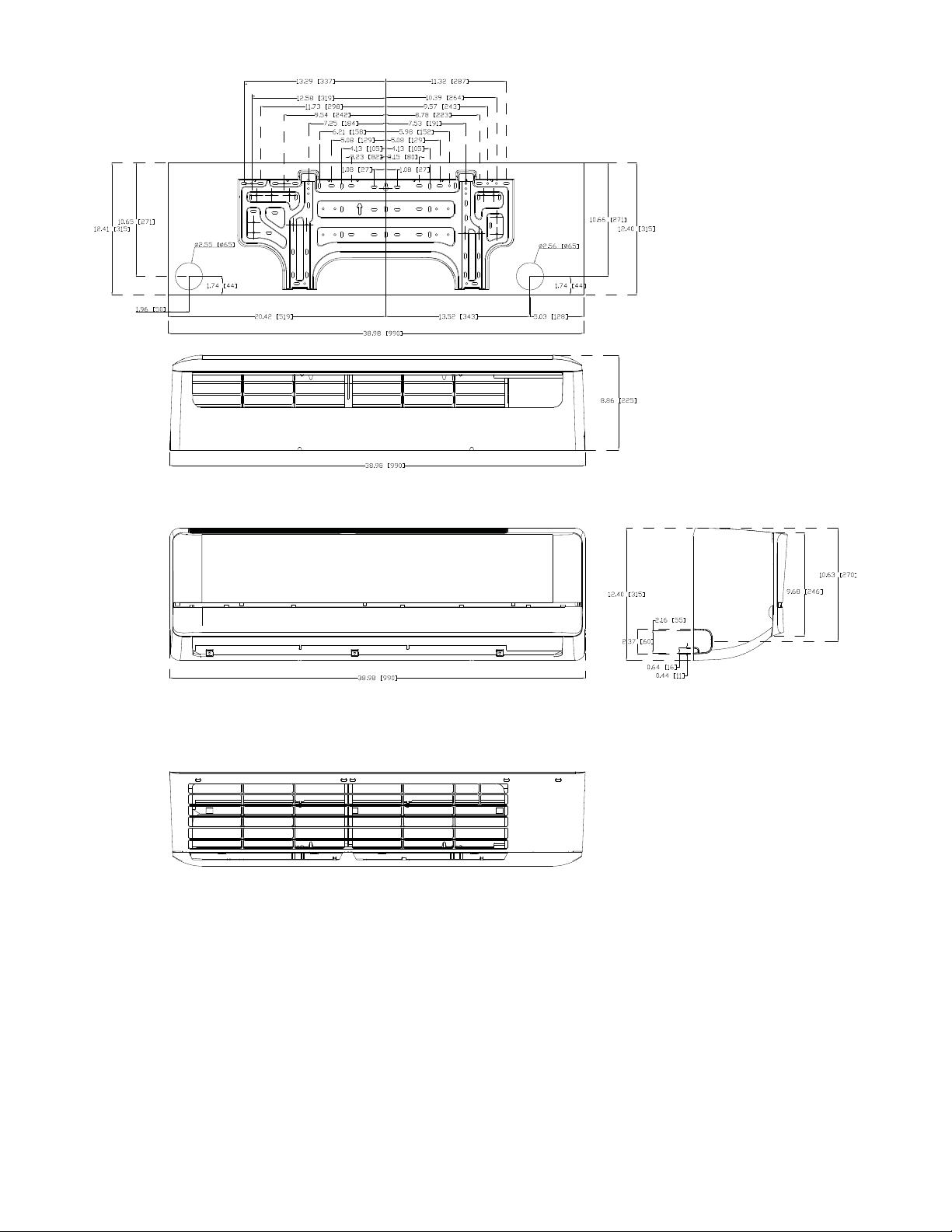
7
DIMENSIONS (CONT)
Fig. 4 - 18K

8
DIMENSIONS (CONT)
Fig. 5 - 24K, 30K, 36K
9
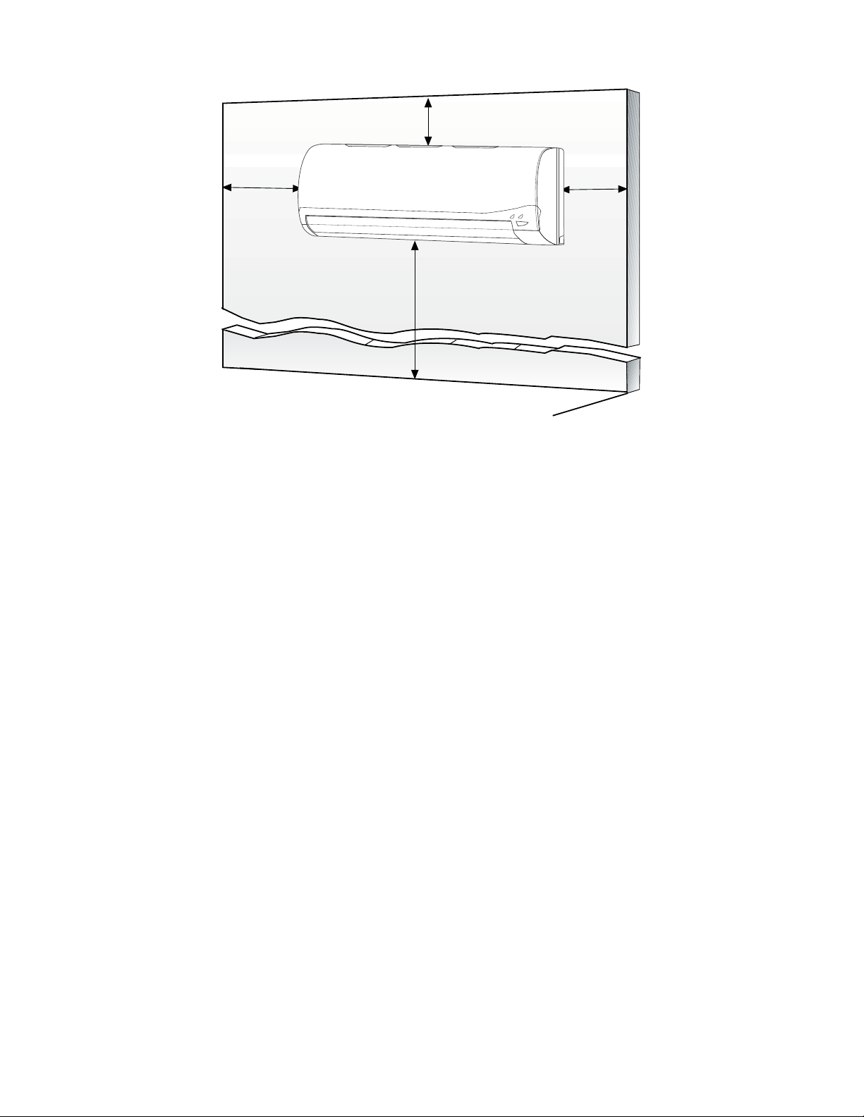
CLEARANCES
6
"
(0.15m
)
min.
5
"
(0.13m)
min.
6'
5
"
(0.13m)
min.
(1.8m)
CEILING
FLOOR
Fig. 6 - Clearances
NOTE: The top clearance recommended for proper return airflow is 5.9in (15cm). Reduction of this clearance may decrease unit
performance. This may be reduced to 3.2in (80mm) as long as the right and left clearances are achieved.
10
INSTALLATION TIPS
Ideal installation locations include:
Indoor Unit
S A location where there are no obstacles near the inlet and outlet
area.
S A location which can bear the weight of the indoor unit.
S Do not install the indoor units near a direct source of heat such as
direct sunlight or a heating appliance.
S A location which provides appropriate clearances (see Fig. 6.)
INDOOR UNIT INSTALLATION
PRIOR TO INSTALLATION
Before installing the indoor unit, ensure the compatibility with the
outdoor unit using the product data as a reference.
Select the Installation Location:
Before installing the indoor unit, choose an appropriate location.
The following are standards that should help you choose an
appropriate location for the unit. Proper installation locations must
meet the following standards:
1. Good air circulation
2. Convenient drainage
3. Noise from the unit will not disturb others
4. Firm and solid—the location will not vibrate
5. A site strong enough to support the unit’s weight
6. A location at least 3.28 ft. (1m) from all other electrical
devices (e.g., TV, radio, computer)
7. DO NOT install the unit in the following locations:
a. Near any source of heat, steam, or combustible gas
b. Near flammable items such as curtains or clothing
c. Near any obstacle that might block air circulation
d. Near the doorway
e. In a location subject to direct sunlight
NOTE: Wall Holes (if there is no fixed refrigerant piping)
While choosing a location, leave ample room for a wall hole (refer
to the Drill Hole in Wall for the Interconnecting Piping, Drain and
Wiring section for connective piping step) for the signal cable and
the refrigerant piping that connect the indoor and outdoor units.
The default position for all piping is the right side of the indoor
unit (while facing the unit). However, the unit can accommodate
piping to both the left and right sides.
Attach the Mounting Plate to the Wall:
1. Carefully remove the mounting plate, which is attached to
the back of the indoor unit.
2. Using the Stencil, determine the wall hole position. The
mounting plate should be located horizontally and level on
the wall. All minimum spacings shown in Fig. 6 should be
maintained.
3. If the wall is block, brick, concrete or similar material, drill
0.2” (5 mm) diameter holes and insert the anchors for the
appropriate mounting screws.
4. Attach the mounting plate to the wall.
Mounting Plate Dimensions
Different model sizes have different mounting plates. Ensure
there’s enough room to mount the indoor unit (refer to Fig. 6). The
following measurements can be located on these figures:
S Width of mounting plate
S Height of mounting plate
S Width of indoor unit relative to plate
S Height of indoor unit relative to plate
S Recommended position of wall hole (both to the left and
right of mounting plate)
S Relative distances between the screw holes.
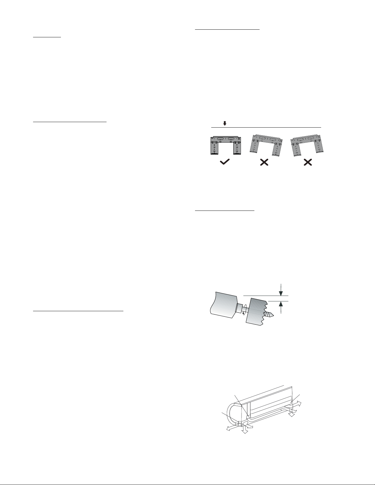
Correct orientation of Mounting Plate
Fig. 7 - Mounting Plate Orientation
DRILL HOLE IN WALL FOR THE
INTERCONNECTING PIPING, DRAIN AND
WIRING
Refrigerant Line Routing
The refrigerant lines may be routed in any of the four directions
shown in Fig. 9.
For maximum serviceability, it is recommended to have refrigerant
line flare connections and the drain connections on the outside of
the wall that the fan coil will be mounted on.
If piping is going through the back:
1. Determine the pipe hole position using the mounting plate as a
template. Drill the pipe hole diameter per values given in Fig.
3. The outside pipe hole is 1/2−in. (13 mm) min. lower than
the inside pipe hole, so it slants slightly downward (see Fig. 8).
1/2 in. (13 mm
)
Min.
I
NDOOR
OUTDOOR
A07371
Fig. 8 - Drill Holes
If piping is going through the right or left side:
1. Use a small saw blade to carefully remove the corresponding
plastic covering on the side panel and drill the appropriate size
hole where the pipe is going through the wall.
Pipe holder
Pipe cover
Right piping
Left piping
Pipe cover
Right back piping
Left back piping
1
2
3
4
A14349
Fig. 9 - Piping Locations
11
ELECTRICAL DATA
Table 5—Electrical Data
HIGH WALL UNIT
SIZE
INDOOR FAN
MAX FUSE CB AMP
V-Ph-Hz FLA HP
9K
115-1-60
0.33 0.053
Refer to outdoor unit installation instructions –
Indoor unit powered by the outdoor unit
12K 0.33 0.053
9K
208/230-1-60
0.33 0.053
12K 0.33 0.053
18K 0.49 0.067
24K 0.61 0.16
30K 0.61 0.16
36K 0.61 0.16
LEGEND
FLA - Full Load Amps
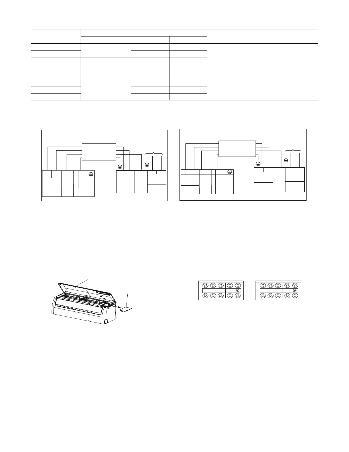
CONNECTION DIAGRAMS
S
L
N
115-1-60
Main
Power Supply
115-1-60
L
N
S
L
N
Power to
Indoor Unit
CONNECTING CABLE
OUTDOOR TO INDOOR
GND
Ground
Indoor
Signal
High
Voltage
115-1-60
115-1-60
FIELD POWER SUPPLY
GND
Indoor
Signal
High
Voltage
Indoor Unit
Power Supply
S
L1 L2
208/230-1-60
Main
Power Supply
L1
L2
S
L1
L2
CONNECTING CABLE
OUTDOOR TO INDOOR
Indoor Unit
Power Supply
208/230-1-60
Indoor
Signal
High
Voltage
GND
Ground
Power to
Indoor Unit
Indoor
Signal
High
Voltage
208/230-1-60
FIELD POWER SUPPLY
GND
208/230-1-60
9K and 12K 115V Indoor Unit 9K and 12K 115V Outdoor Unit 9K to 36K 230V Indoor Unit 9K to 36K 230V Outdoor Unit
Fig. 10 - Connection Diagrams
Notes:
1. Do not use thermostat wire for any connection between indoor and outdoor units.
2. All connections between indoor and outdoor units must be as shown. The connections are sensitive to polarity and will result in a fault code.
TERMINAL BLOCK LOCATION
1. Open the indoor unit’s front panel.
2. Using a screwdriver, open the wire box cover on the right side of the unit, then open the terminal block cover. This reveals the terminal
block.
Electrical box
cover
Front Panel
Fig. 11 - Terminal Block Location
LNS L1 L2 S
9K and 12K 115V 9K to 36K 208/230V
Fig. 12 - Control and Power Wiring on Indoor Unit
12
INSTALL ALL POWER, INTERCONNECTING
WIRING, AND PIPING TO THE INDOOR UNIT
1. Run interconnecting piping and wiring from the outdoor
unit to the indoor unit.
2. Run an interconnecting cable through the hole in wall
(outside to inside).
3. Lift the indoor unit into position and route piping and drain
through the hole in wall (inside to outside). Fit the
interconnecting wiring into the back side of the indoor unit.
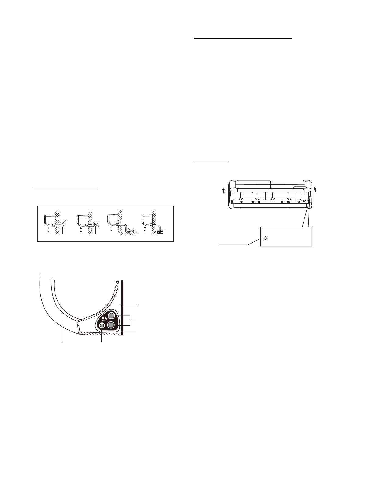
4. Put an upper claw at the back of the indoor unit on the up-
per hook of the Mounting Plate, move the indoor unit from
side to side to ensure it is securely hooked.
5. Open the indoor unit’s front cover and remove the field
wiring terminal block cover.
6. Pull the interconnecting wire up from the back of indoor
unit and position close to the terminal block on the indoor
unit.
7. Push the lower part of the indoor unit up on the wall, then
move the indoor unit from side to side, up and down to
ensure it is hooked securely (see Fig. 13).
Upper hook
Lower hoo
k
Fig. 13 - Indoor Unit Installation
8. Connect the wiring from the outdoor unit per the
connection diagram (see Fig. 10 and Fig. 12).
9. Replace the field wiring cover and close the front cover of the
indoor unit.
10. Piping:
a. Cut the pipe, with a pipe cutter, at 90 degrees (see Fig. 14).
b. Remove the service connection, if provided with the unit.
Oblique
DŽ
90
Roughness
Burr
A150767
Fig. 14 - Pipe Cutting
c. Remove all the burrs from the cut cross section of the pipe
avoiding any burrs inside the tubes.
d. Remove the flare nuts attached to the indoor and outdoor
units.
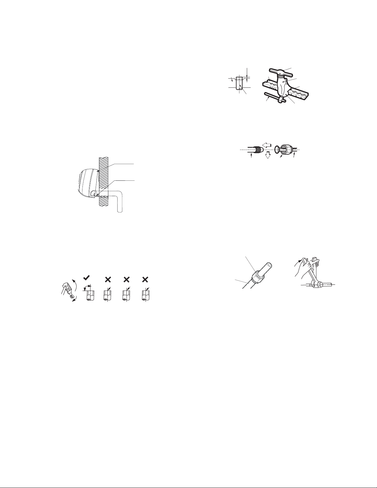
e. Install the correct size flare nut onto the tubing and make
the flare connection. Refer to Table 6 for the flare nut
spaces.
Table 6—Flare Nut Spacing
OUTER DIAM. (mm)
A (mm)
Max. Min.
Ø 1/4" (6.35) 0.05 (1.3) 0.03 (0.7)
Ø 3/8" (9.52) 0.06 (1.6) 0.04 (1.0)
Ø 1/2" (12.7) 0.07 (1.8) 0.04 (1.0)
Ø 5/8" (15.88) 0.09 (2.2) 0.08 (2.0)
Bar
Copper pipe
Clamp handle
Red arrow mark
Cone
Yoke
Handle
Bar
"A"
Fig. 15 - Flare Nut Spacing
f. Apply a small amount of refrigerant oil to the flare
connection on the tubing.
g. Align the center of the pipes and/or service valve.
Indoor unit tubing Flare nut Piping
A150769
Fig. 16 - Align Pipe Center
h. Connect both the liquid and gas piping to the indoor unit
i. Tighten the flare nut using a torque wrench as specified in
Table 7.
Table 7—Tightening Torque
PIPE DIAMETER
INCH (mm)
TIGHTENING TORQUE
Ft-lb N-m
Ø1/4” (6.35) 10 to 13 13.6 to 17.6
Ø3/8” (9.52) 24 to 31 32.5 to 42.0
Ø1/2” (12.7) 37 to 46 50.1 to 62.3
Ø5/8” (15.88) 50 to 60 67.7 to 81.3
Flare nut
Copper tube
A150770
Fig. 17 - Tighten the Flare Nut
13
FINAL TUBING CHECK
IMPORTANT: Ensure the certain factory tubing on the indoor
unit has not shifted during shipment. Ensure the tubes are not
rubbing against each other or any sheet metal. Pay close attention
to feeder tubes and make sure the wire ties on the feeder tubes are
secure and tight.
DRAIN CONNECTIONS
Connect the drain line. The drain line must not have a trap anywhere
in its length, must pitch downwards, and must be insulated up to the
outside wall (see Fig. 18). By default, the drain hose is attached to the
left−hand side of unit (when facing the back of the unit). However, it
can also be attached to the right−hand side.
a. To ensure proper drainage, attach the drain hose on the
same side that your refrigerant piping exits the unit.
b. Attach a drain hose extension (purchased separately) to
the end of the drain hose.
c. Wrap the connection point firmly with Teflon tape to
ensure a good seal and to prevent leaks.
d. For the portion of the drain hose that remains indoors,
wrap it with foam pipe insulation to prevent
condensation.
e. Remove the air filter and pour a small amount of water
into the drain pan to ensure that water flows from the
unit smoothly.
Plug the Unused Drain Hole
To prevent unwanted leaks, plug the unused drain hole with the
rubber plug provided.
Proper Do not put drain end into waterDo not form a rise
A14351
Fig. 18 - Proper Drain Hose Installation
NOTE: For proper orientation of the refrigerant piping, electrical
cable and drain lines, refer to Fig. 19.
Indoor Unit
Space behind unit
Refrigerant piping
Drain hose
Signal wire
Insulation tape
A07346
Fig. 19 - Bundle drain hose, refrigerant pipes, and signal
cable
NOTE: It is not recommended to add additional insulation to the
refrigerant pipes provided with the product. The factory insulation
is sufficient. Additional insulation may keep the product from
attaching flush to the wall.
NOTE: For applications where gravity cannot be used for
drainage, a condensate pump accessory is available. Consult the
condensate pump Installation Instructions for more information.
WIRELESS REMOTE CONTROL
INSTALLATION
Mounting Bracket (if installed on the wall)
1. Use the two screws supplied with the wireless remote
control to attach the mounting bracket to the wall in a
location selected by the customer and within operating
range.
2. Install the batteries in the remote control.
3. Place the remote control into the remote control mounting
bracket.
NOTE: For remote control operation, refer to the unit Owner’s
Manual.
WIRED REMOTE CONTROL
INSTALLATION
For setup instructions, refer to the wired control installation
manual.
START−UP
Test Operation
Perform a test operation after completing a gas leak and electrical
safety check (see Fig. 20).
Manual control
button
AUTO/COOL
A14353
Fig. 20 - Test Operation
1. Push ON/OFF on the remote control to begin testing.
NOTE: A protection feature prevents the air conditioner from
activating for approximately 3 to 4 minutes.
2. Push MODE, select COOLING, HEATING, FAN mode
to check that all functions work correctly.
3. To run the test using the MANUAL button in the indoor
unit:
a. Open the front panel of the indoor unit;
b. Push the manual switch once to energize the unit. The set
conditions of manual operation are as follows:
· Preset set point: 76_F (24_C)
· Fan speed: AUTO
· Discharge air direction: Pre−set position based on
operation in COOL or HEAT mode.
4. Be sure to set manual switch to OFF (by pushing it twice
again) after finishing test operation.

14
SYSTEM CHECKS
1. Conceal the tubing where possible.
2. Ensure the drain tube slopes downward along its entire
length.
3. Ensure all tubing and connections are properly insulated.
4. Fasten tubes to the outside wall, when possible.
5. Seal the hole through which the cables and tubing pass.
INDOOR UNIT
1. Do all remote control buttons function properly?
2. Do the display panel lights work properly?
3. Does the air deflection louver function properly?
4. Does the drain work?
Explain Following Items To Customer
(with the aid of the Owner’s Manual):
1. How to turn air conditioner on and off; selecting
COOLING, HEATING and other operating modes; setting
a desired temperature; setting the timer to automatically start
and stop the air conditioner operation; and all other features
of the remote control and display panel.
2. How to remove and clean the air filter.
3. How to set air deflection louver.
4. Explain care and maintenance.
5. Present the Owner’s Manual and installation instructions to
customer.
TROUBLESHOOTING
For ease of service, the systems are equipped with diagnostic code
display LEDs on both the indoor and outdoor units. The indoor
diagnostic display is a combination of flashing LEDs on the
display panel or the front of the unit.
Some indoor units display error codes specifying failure modes in
the outdoor units. If possible, always check the diagnostic codes
displayed on the indoor unit first.
The diagnostic codes displayed in the indoor and outdoor units are
listed in Table 8.
INDOOR UNIT DIAGNOSTIC GUIDES
Table 8—ID Units Error Code Display
OPERATION LAMP TIMER LAMP DISPLAY LED STATUS
☆ 1 time
X E0 Indoor unit EEPROM parameter error
☆ 2 times
X E1 Indoor / outdoor units communication error
☆ 3 times
X E2 Zero-crossing signal detection error
☆ 4 times
X E3 Indoor fan speed is out of control
☆ 5 times
X E4 Indoor room temperature sensor T1 open circuit or short circuit
☆ 6 times
X E5 Evaporator coil temperature sensor T2 open circuit or short circuit
☆ 7 times
X EC Refrigerant leakage detection
☆1 time
O F0 Overload current protection
☆ 2 times
O F1 Outdoor ambient temperature sensor T4 open circuit or short circuit
☆ 3 times
O F2 Condenser coil temperature sensor T3 open circuit or short circuit
☆ 4 times
O F3 Compressor discharge temperature sensor T5 open circuit or short circuit
☆ 5 times
O F4 Outdoor unit EEPROM parameter error
☆ 6 times
O F5 Outdoor fan speed is out of control
☆ 1 time ☆
P0 IPM malfunction or IGBT over-strong current protection
☆ 2 times ☆
P1 Over voltage or over low voltage protection
☆ 3 times ☆
P2
High temperature protection of the compressor top diagnosis and solution
(only for 9k,12k models)
☆ 5 times ☆
P4 Inverter compressor drive error
O (on − light) X(off − light) ☆(flash)
For additional diagnostic information, refer to the Service Manual
Copyright 2017 Carrier Corporation S 7310 W. Morris St. S Indianapolis, IN 46231
Manufacturer reserves the right to change, at any time, specifications and designs without notice and without obligations.
Catalog No: 40MAQ-03SI
Replaces: 40MAQ-02SI
Edition Date: 10/17