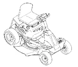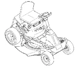
Automatic Lawn Tractor Horse TM(Model 60TP)
READ SAFETY RULES AND mNSTRUCTmONS CAREFULLY BEFORE OPERATmON
Warning: This unitis equippedwithan internalcombustionengineandshouldnot beusedon or nearany unimprovedforest-covered,brush=
coveredor grass=coveredlandunlessthe engine'sexhaustsystemis equippedwitha sparkarrestermeetingapplicablelocalorstate laws(if any),
If a sparkarresteris used,it shouldbemaintainedineffectiveworkingorderby the operator,Inthe Stateof Californiathe aboveis requiredbylaw
(Section4442of the CaliforniaPuNicResourcesCode),Otherstatesmayhavesimilarlaws,Federallawsapplyonfederallands,A sparkarrester
for the muffleris availablethroughyournearestengineauthorizedservicedealeror contactthe servicedepartment,RO,Box361131Cleveland,
Ohio44136=0019,
FORMNO,770=10189I
PRINTEDIN U,S,A Troy-Bilt LLC, P.O. BOX 361131 CLEVELAND, OHIO 44136-0019 01/06/2006
This Operator's Manua_ is an important part of your new lawn tractor, mtwH_ he_p you assemble,
prepare and maintain the unit for best performance. P_ease read and understand what it says.
Table of Contents
Slope Gauge ....................................................... 3
Safe Operation Practices ................................... 4
Setting Up Your Lawn Tractor ............................ 8
Operating Your Lawn Tractor ........................... 10
Adjusting Your Lawn Tractor ............................ 18
Maintaining Your Lawn Tractor ........................ 20
Off-Season Storage / Attachments ................. 26
Safety Labels .................................................... 27
TrouMe Shooting .............................................. 28
Parts List ........................................................... 30
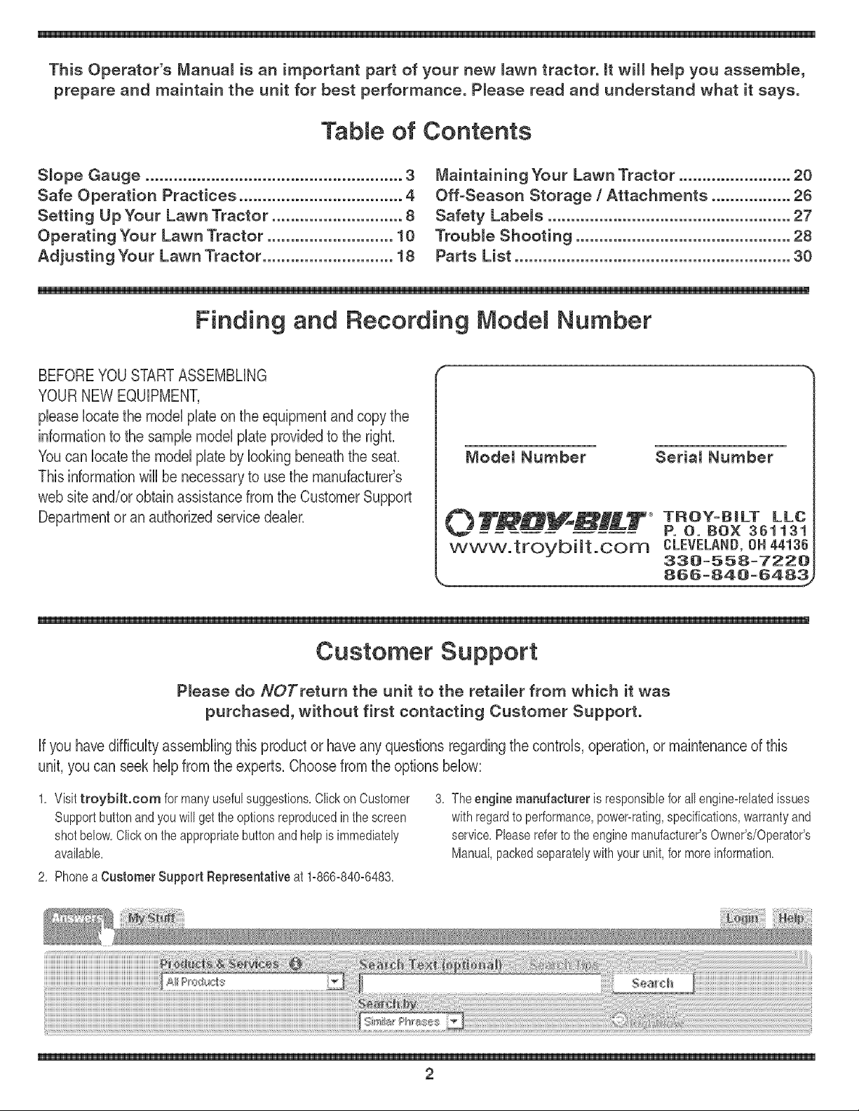
Finding and Recording Model Number
BEFOREYOU START ASSEMBLING
YOUR NEW EQUIPMENT,
please locatethe model plate on the equipment and copy the
information to the sample model plate providedto the righL
You can locate the model plate by looking beneath the seal
This information will be necessary to use the manufacturer's
web site and/or obtain assistance from the Customer Support
Department or an authorized service dealer.
Modem Number Seriam Number
0 TR#_H_--T_ TROY=BiLT LLC
P. O. BOX 361131
www.troybiit.com CLEVELAND, ON 44136
338=558=7228
,, 856=848=6483_
Customer Support
P_ease do NOTreturn the unitto the retai_er from which it was
purchased, without first contacting Customer Support.
if you have difficulty assembling this product or have any questions regarding the controls, operation, or maintenance of this
unit, you can seek help from the expert& Choose from the options below:
1, Visittroybilt.com for manyusefulsuggestions,Clickon Customer
Supportbuttonandyouwill get the optionsreproducedin thescreen
shotbelow,CIbk onthe appropriatebuttonandhelpis immediately
availabb,
3, The engine manufacturer is responsibbforall engine=relatedissues
with regardto performance,power=rating,specifications,warrantyand
service,Phase referto the enginemanufacturer'sOwner's/Operator's
Manual,packedseparatelywithyour unit,for moreinformation,
2, Phonea Customer Support Representative at 1=866-840=6483,
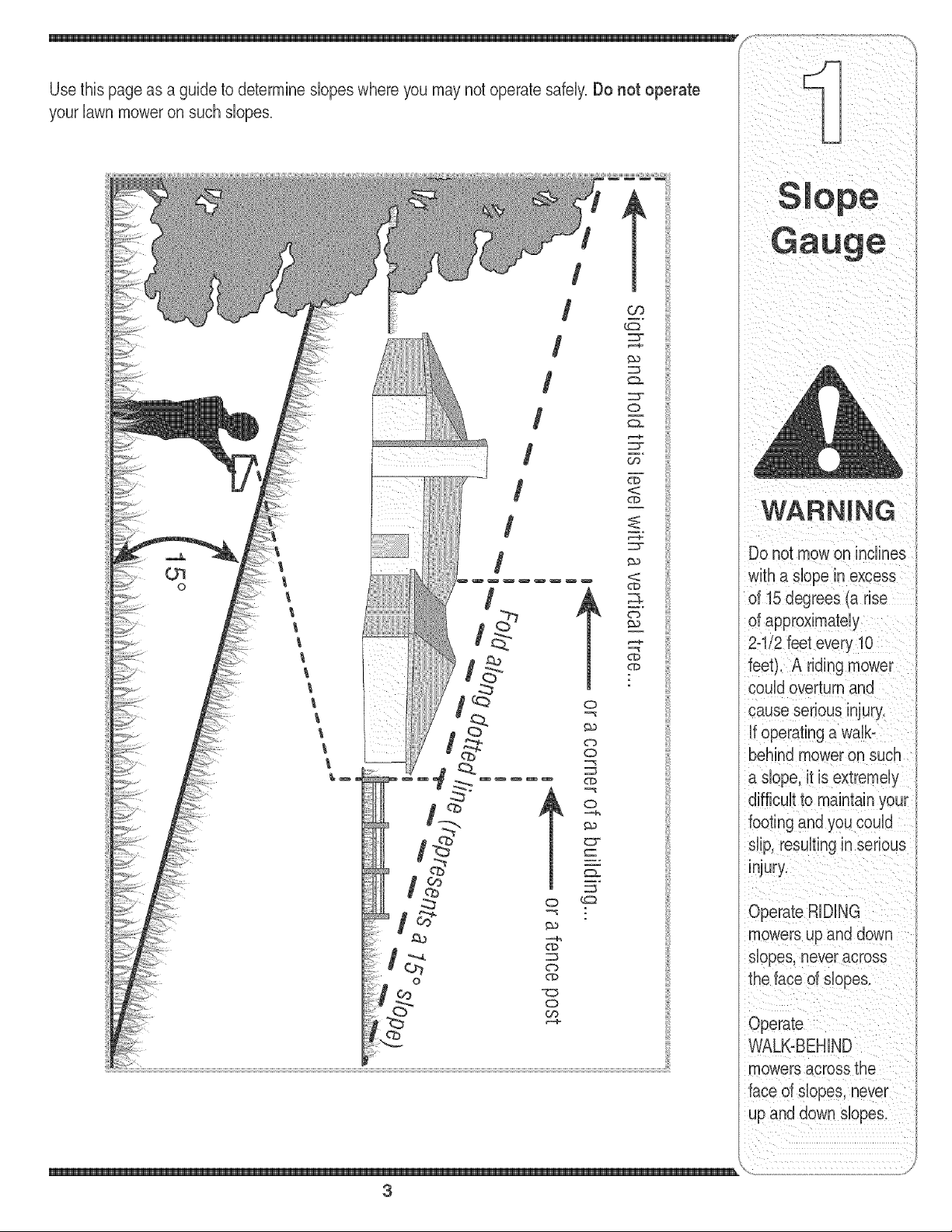
your lawn mower on such slopes.
/
/
/
/
o
/
/
t
o
w_
WARNING
Do not mowon inclines
with a dope in excess
of 15 degrees (a rise
of approximately
2-"
feet). A riding r
could overturn and
cause serious injury.
if operating a walb
behind mower on such
a dope, it is extremely
footing and you could
dip, resulting in serious
injury.
Operate RiDiNG
mowers up and down
dopes, neveracross
the face of dopes.
Operate
WALK-BEHIND
mowers across the
face of dopes, never
up and down slopes.
\
3
_i i _ i _i _ i _ iii _ _
DANGER: This machine was built to be operated according to the rubs for safe operation in this
manuak As with any type of power equipment, carelessness or error on the part of the operator can
S ale result in serious injury. This machineis capable of amputating hands and feet and throwing objects.
Failureto observe the following safety instructions could result in serious injury or death.
instructionswhich, if
notfollowed, could
endangerthe personal
safety and/or property
of yourself and others.
Read and fobow all
instructionsin this man=
ual before attemptingto
operatethis machine.
Failureto comply with
When you see this
symbol.
H EED ITS WARNING
Your
Responsibility
Restrictthe use
of this power machine
to persons who read.
understand
and follow the warnings
and instructions
in this manual
Children
1. Tragicaccidentscan occurif the operatoris not
abrt tothe presenceof children.Childrenare often
attractedto the machineandthe mowingactivity.
Theydo not understandthe dangers.Neverassume
thatchildrenwill remainwhereyou lastsawthem.
a. Keepchildrenout of the mowingarea andin
watchfulcare of a responsibleadult otherthan
the operator.
b. Bealert and turn machineoff if a childenters
the area.
c. Beforeand while backing,lookbehindand
downfor smallchildren.
d. Nevercarrychildren,evenwiththe blade(s)
shutoff.Theymayfalloffandbeseriously
iniuredor interferewith safemachineoperation.
e. Useextremecarewhenapproachingblind
corners,doorways,shrubs,treesor other
objectsthatmayblockyourvisionof a child
who mayrun into the machine.
f. To avoid back-overaccidents, always
disengage the cutting blade(s) before
shifting into Reverse. If equipped, the
"Reverse Caution Mode" should not be
used when children or others are around.
g. Keepchildrenaway from hotor running
engines.Theycansuffer burnsfroma hot
muffler.
h. Removekeywhen machineis unattendedto
preventunauthorizedoperation.
2. Neverallowchildrenunder14yearsoldto operate
the machine.Children14}'earsoldandovershould
readandunderstandthe operationinstructionsand
safetyrubs inthis manualand shouldbe trainedand
supervisedbya parent.
Operation
Safe Handling of Gasoline:
1. Toavoid personal injuryor property damage use
extreme care in handlinggasoline. Gasoline is
extremely flammable and the vapors areexplo-
sive. Seriouspersonaliniurycanoccurwhengasoline
is spilledonyourselfor yourclotheswhichcan ignite.
Washyourskinandchangeclothesimmediately.
a. Useonlyan approvedgasolinecontainer.
b. Neverfill containersinsidea vehbb or ona
truckor trailerbedwitha plastb liner.Always
placecontainerson the groundawayfrom
yourvehble beforefilling.
c. When practbal, removegas-powered
equipmentfromthe truck or trailerand refuelit
onthe ground.If this is not possibb, then
refuelsuchequipmentona trailerwitha
portabb container,ratherthan from a gasoline
dispensernozzb.
d. Keepthe nozzb in contactwiththe rimof
the fueltank or containeropeningat all
timesuntilfuelingis complete.Donot usea
nozzleIocbopendevice.
e. Extinguishall cigarettes,cigars,pipesand
othersourcesof ignition.
f. Neverfuel machineindoors.
g. Neverremovegas cap or add fuel whilethe
engineis hot or running.Mow engineto cool
at bast twominutesbeforerefueling.
h. Neveroverfill fuel tank.Fill tank to nomore
than1/2inchbelowbottomof filbr neckto
allowspacefor fuel expansion.
i. Replacegasolinecapand tightensecurely.
i. If gasolineis spilled,wipe it off the engine
andequipment.Moveunitto anotherarea.
Wait5 minutesbeforestartingthe engine.
k. To reducefire hazards,keepmachinefreeof
grass,leaves,orother debrisbuild-up.Clean
upoil orfuel spillageand removeany fuel
soakeddebris.
I. Neverstorethe machineor fuel container
insidewherethere is an open flame,spark
or pilotlightas on a waterheater,space
heater,furnace,clothesdryeror othergas
appliances.
m. Allowa machineto cool at bast five minutes
beforestoring.
4
GeneralOperation:
1. Read,understand,andfollowall instructionson the
machineandinthe manual(s)beforeattemptingto
assembleandoperate.Keepthismanualina safe
placefor futureandregularreferenceandforordering
replacementparts.
2. Be familiarwith all controlsand theirproperoperation.
Knowhow to stopthe machineand disengagethem
quickly.
3. Neverallowchildrenunder 14yearsold to operate
this machine.Children14yearsold andovershould
readandunderstandthe operationinstructionsand
safetyrubs in thismanualand shouldbe trainedand
supervisedby a parent.
4. Neverallowadults to operatethis machinewithout
properinstruction.
5. To helpavoid bladecontactor a thrownobiect iniury,
keepbystanders,helpers,childrenand petsat bast
75 feetfromthe machinewhileit is in operation.8top
machineif anyoneentersthe area.
6. Thoroughlyinspecttheareawherethe equipmentis to
beused.Removeallstones,sticks,wire,bones,toys,
andotherforeignobiectswhichcould be pickedup
andthrownbythe blade(s).Thrownobiectscancause
seriouspersonaliniury.
7, Planyourmowingpatternto avoiddischargeof
materialtowardroads,sidewalks,bystandersandthe
like.Also,avoiddischargingmaterialagainsta wall or
obstructionwhichmaycausedischargedmaterialto
ricochetbacktowardthe operator.
8. Alwayswearsafetyglassesor safetygogglesduring
operationandwhile performingan adiustmentor
repairto protectyour eyes.Thrownobiectswhich
ricochetcan causeseriousiniuryto the eyes.
9. Wearsturdy,rough-sobdworkshoesandclose-fitting
slacksandshirts.Loosefittingclothesand iewelry
can be caught in movabb parts. Neveroperatethis
machinein barefeetor sandals.
10.Beawareof the mowerand attachmentdischarge
directionanddo notpoint it at anyone.Do notoperate
the mowerwithoutthe dischargecoveror entiregrass
catcherin itsproperplace.
11.Do notput handsor feet near rotatingpartsor under
the cuttingdeck.Contactwith the blade(s)can
amputatehandsandfeet.
12.Amissingor damageddischargecovercan cause
bladecontactor thrownobiectiniuries.
13.8topthe blade(s)whencrossinggraveldrives,walks,
or roadsandwhilenot cuttinggrass.
14.Watchfor trafficwhenoperatingnearor crossing
roadways.Thismachineis not intendedfor useon
anypublic roadway.
15.Do notoperatethe machinewhileunderthe influ-
enceof alcoholor drugs.
16.Mowonly in daylightor goodartificiallight.
17,Nevercarrypassengers.
18.Disengageblade(s)beforeshiftinginto reverse.
Backup slowly.Alwayslookdownandbehind before
andwhilebackingto avoida back-overaccident.
19.Slowdownbeforeturning.Operatethe machine
smoothly.Avoiderraticoperationand excessive
instructions wh ch. if
not followed, could
endanger the personal
safety and/or property
of yourself and others.
Read and follow all
instructions in this man-
ual before attempting to
operatethis machine.
these instructions may
result in personal injury.
When you see this
symbol.
HEED iTS WARNING
Your
Responsibility
Restrictthe use
d this power machine
to persons who read,
understand
and follow the warninas
and instructions
in this manual
5
21.Neverleavea runningmachineunattended.Always
turnoff blade(s),placetransmissionin neutral,set
parkingbrake,stopengineand removekeybefore
dismounting.
22.Useextracare whenloadingor unloadingthe
machineintoa trailerortruck. This unitshould not
bedrivenup or downramp(s),becausethe unit
couldtip over,causingseriouspersonaliniury.The
unit mustbe pushedmanuallyon ramp(s) to load or
unloadproperly.
23.Mufflerandenginebecomehotand can causea
burn.Do nottouch.
24.Checkoverheadclearancescarefullybeforedriving
underlowhangingtreebranches,wires,dooropen-
ingsetc. wheretheoperatormaybe struckor pulled
fromthe unit,which couldresult in seriousiniury.
25.Disengageallattachmentclutches,depressthe
brakepedalcompbtelyand shift into neutralbefore
attemptingto startengine.
26.Yourmachineis designedto cut normalresidential
grassof aheightno morethan 10".Do notattemptto
mowthroughunusuallytall,dry grass (e.g.,pasture)
or pilesof dry leaves.Drygrassor leavesmay
contactthe engineexhaustand/orbuild up on the
mowerdeckpresentinga poten%l fire hazard.
27.Useonlyaccessoriesandattachmentsapprovedfor
thismachineby the machinemanufacturer.Read,
understandandfollowall instructionsprovidedwith
the approvedaccessoryor attachment.
28.Dataindicatesthatoperators,age 60 yearsand
above,areinvolvedin a large percentageof riding
mower-relatediniuries.Theseoperatorsshould
evaluatetheirabilityto operatetheridingmower
safelyenoughto protectthemselvesandothers from
seriousiniury.
29.If situationsoccurwhicharenot coveredin this
manual,usecareandgood iudgment.Contactyour
customerservicerepresentativefor assistance.
WARNING
This symbol points
speed. }
20.Dbengageblade(s),setparkingbrake,stop engine
andwait untilthe blade(s)cometo a completestop
beforeremovinggrasscatcher,emptyinggrass,
uncloggingchute,removingany grassor debris,or
makinganyadiustments.
Slope Operation:
Slopesarea majorfactorrelatedto loss of controland
tip-overaccidentswhichcan resultin severeinjury or
death,All slopesrequireextracaution,if you cannot
backup the slopeor if youfeel uneasyon it, do notmow
it,
Foryour safety,usethe slopegauge includedas partof
thismanualto measureslopesbeforeoperatingthis unit
ona slopedor hillyarea,if the slopeis greaterthan 15
;_,_ degreesas shownon the slopegauge,do notoperate
,, thisunit on that area or serious injurycouldresult,
uperal:lon Do:
1, Mowupanddownslopes,notacross,Exercise
racl:lces extremecautionwhenchangingdirectiononsbpes,
2, Watchfor hobs, ruts,bumps,rocks,or other hidden
objects,Uneventerraincouldoverturnthe machine,
out important safety
instructions which, if
not followed, could
endangerthe personal
safety and/or property
of yourself and others.
Readand follow all
instructions in this man°
ual before attempting to
Tallgrasscan hide obstacbs,
3, Useslowspeed,Choosea low enoughspeed
settingso that youwill not haveto stop or shift while
onthe slope,Tires may losetractionon slopeseven
thoughthe brakesarefunctioningproperly,Always
keepmachineingear whengoingdownslopes to
takeadvantageof enginebrakingaction,
4, Followthe manufacturer'srecommendationsfor
wheelweightsorcounterweightsto improvestability,
5, Useextracarewithgrasscatchersor otherat-
tachments,Thesecanchangethe stabilityof the
machine,
6, Keepall movementon theslopesslowandgradual
Do not makesuddenchangesinspeedor direction,
Rapidengagementor brakingcouldcausethe front
of the machineto lift and rapidlyfib overbackwards
whichcouldcauseseriousinjury,
7, Avoidstartingor stoppingon a slope,If tireslose
traction,disengagethe blade(s)and proceedslowly
straightdownthe slope,
Do Not:
1, Do notturn on slopes unlessnecessary;then,turn
slowlyandgraduallydownhill,if possibb,
2, Do not mownear drop-offs,ditchesor embankments,
The mowercouldsuddenlyturnoverif awheel is over
the edgeof a cliff, ditch,or if an edge cavesin,
3, Do nottry to staNlizethe machineby puttingyourfoot
onthe ground,
4, Do not usea grasscatcheron steep slopes,
5, Do not mowon wet grass,Reducedtractioncould
causesliding,
6, Do notshift to neutraland coastdownhill Over-speed-
ingmaycausethe operatorto lose controlof the
machineresultingin seriousinjuryordeath,
7, Do nottow heavypull behindattachments(e,g,loaded
dumpcart, lawnroller,etc,)on slopesgreaterthan
5 degrees,Whengoingdown hill,the extra weight
tendsto pushthetractorand maycauseyou to loose
control (e,g,tractormayspeedup, brakingand steer-
ingabilityare reduced,attachmentmayjack-knifeand
causetractorto overturn),
Towing:
1, Towonlywitha machinethat hasa hitchdesignedfor
towing,Do not attachtowedequipmentexceptat the
hitchpoint,
2, Followthe manufacturersrecommendationfor weight
limitsfor towedequipmentandtowingon slopes,
3, Neverallowchildrenor othersin oron towedequip-
ment,
4, Onslopes,theweightof thetowed equipmentmay
causelossof tractionand loss of control,
5, Travelslowlyandallowextradistanceto stop,
6, Do notshift to neutraland coastdownhill
these instructions may
result in personal injury,
When you see this
symbol
HEED ITS WARNING
YOUr
Responsibility
Restrictthe use
of this power machine
to persons who read.
understand
and follow the warnings
and instructions
in this manual
6
Service lO,Neverattemptto makeadiustmentsor repairsto the
1. Neverrun anengineindoorsor ina poorlyventilated
area. Engineexhaustcontainscarbonmonoxide,an
odorless,anddeadlygas.
2. Beforecleaning,repairing,or inspecting,makecertain
the blade(s)and all movingparts havestopped.
Disconnectthe sparkplug wireand groundagainstthe
engineto preventunintendedstarting.
3. Periodicallycheckto make surethe bladescome to
compbte stop withinapproximately(5) fiveseconds
afteroperatingthe bladedisengagementcontrol,if the
bladesdo notstopwithin thethis time frame,your unit
shouldbeservicedprofessionallyby anauthorized
MTDServiceDealer.
4. Checkbrakeoperationfrequentlyas it is subiectedto
wearduringnormaloperation.Adiustandserviceas
required.
5. Checkthe blade(s)and enginemountingboltsat
frequentintervalsfor propertightness.Also,visually
inspectblade(s)for damage(e.g. excessivewear,
bent,cracked). Replacethe blade(s)with theoriginal
equipmentmanufacturer's(O.E.M.)blade(s)only,
listedin thismanual."Useof partswhichdonot meet
the originalequipmentspecificationsmaybad to
improperperformanceandcompromisesafety!"
6. Mowerbladesare sharp.Wrapthe bladeor wear
gloves,anduseextra cautionwhenservicingthem.
7, Keepall nuts,bolts,and screwstight to be surethe
equipmentis insafeworkingcondition.
8. Nevertamperwith the safety interlocksystemor other
safetydevices.Checktheir properoperationregularly.
9. Afterstrikinga foreignobiect,stopthe engine,
disconnectthe spark plug wire(s)and groundagainst
the engine.Thoroughlyinspectthe machinefor any
damage.Repairthe damagebeforestartingand
operating,
machinewhile theengineis running,
11,Grasscatchercomponentsandthe discharge
coveraresubiectto wearand damagewhichcould
exposemovingpartsor allowobiectsto be thrown,
Forsafetyprotection,frequentlycheckcomponents
ii
andreplaceimmediatelywithoriginalequipment
manufacturer's(O,E,M,)partsonly,listed in this
manual,"Useof partswhichdo notmeettheoriginal
equipmentspecificationsmaybad to improper
performanceandcompromisesafety!"
12,Do notchangethe enginegovernorsettingsor
over-speedthe engine,The governorcontrolsthe
maximumsafeoperatingspeedof theengine,
13,Maintainor replacesafetyandinstructionlabels,as
necessary,
14,Observeproperdisposallawsandregulationsfor
gas,oil,etc, to protecttheenvironment,
i /
This symbol points
instructions which, if
safety and/or property
of yourself and others,
Readand follow al
ual before attempting to
operatethis machine.
When you see this
symbol,
N EED roTSWARNING
Your
Responsibility
Restrictthe use
of this power machine
to persons who read,
understand
>wthe warnings
and instructions
in this manual
\
7
Use extremecare
gasoline. Gasol!ne is
extremely flammab!e
and theVaporsare
explos!ve. Never fuel
machine indoors
orwhiletheengine
is hot or running.
Ext ,g, shcigarettes,
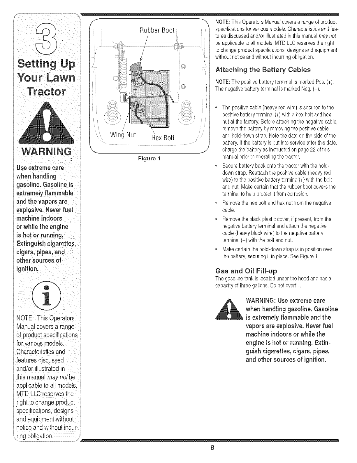
Wini Nut
Hex Bolt
Figure 1
Attaching the Battery Cables
NOTE:Thepositivebatteryterminalis markedPos,(+),
The negativebatteryterminalis markedNeg,(-),
The positivecable(heavyredwire) is securedto the
positivebatteryterminal(+)witha hexbolt and hex
nut at thefactory.Beforeattachingthe negativecable
removethe batteryby removingthe positivecable
andhold=downstrap.Notethe dateon theside of the
battery,if the batteryis put into serviceafter this date,
chargethe batteryas instructedon page22 of this
manualpriorto operatingthe tractor.
. Securebatteryback ontothe tractorwiththe hold=
downstrap.Reattachthe positivecable (heavyred
wire)to the positivebatteryterminal(+)withthe bolt
andnut. Makecertain that the rubberbootcoversthe
terminalto helpprotectit fromcorrosion.
• Removethehex bolt and hexnut from the negative
cable.
• Removetheblack plasticcover,if present,from the
negativebatteryterminalandattachthe negative
cable(heavyblackwire)to the negativebattery
terminal(-) with the boltand nut.
• Makecertainthehold=downstrapis in positionover
the battery,securingit inplace,See Figure1,
Gas and Oil Fill-up
The gasolinetank is locatedunderthe hood and hasa
capacityof threegallons,Do notoverfill,
WARNING: Use extreme care
when handling gasoline. Gasoline
is extremely flammable and the
vapors are explosive. Never fuel
machine indoors or while the
engine is hot or running. Extin-
guish cigarettes, cigars, pipes,
and other sources of ignition.
8
Servicethe enginewith gasolineand oil as instructedin f
the separateKohlerOperator/OwnerManualpackedwith
yourtractor,Readinstructionscarefully,
IMPORTANT:Yourtractoris shippedwithmotoroil inthe
engine,However,you MUSTcheckthe oillevel before
operating,Becarefulnot to overfill,
Shipping Brace Remova_
WARNING: Make sure the riding
mower's engine is off, remove the
ignition key, and set the parking
brake before removing the ship-
ping brace.
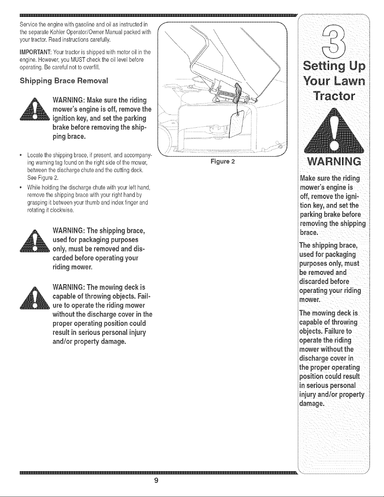
Locatethe shippingbrace,if present,and accompany-
ingwarningtagfoundon the rightside of the mower,
betweenthe dischargechuteandthe cuttingdeck,
SeeFigure2,
• While holdingthe dischargechutewith yourleft hand,
removetheshippingbracewithyourright handby
graspingit betweenyourthumband indexfingerand
rotatingit clockwise,
Figure 2
WARNING: The shipping brace,
used for packaging purposes
only, must be removed and dis-
carded before operating your
riding mower.
WARNING: The mowing deck is
capable of throwing objects. Fail-
ure to operate the riding mower
without the discharge cover in the
proper operating position could
result in serious personal injury
and/or property damage.
Your Lawn
Tractor
WARNING
Make sure the riding
mower's engine is
off, remove the igni-
tion key, and set the
parking brake before
removing the shipping
brace.
The shipping brace,
used for packaging
purposes only, must
be removed and
discarded before
operating your riding
mower.
The mowing deck is
capable of throwing
objects. Failure to
operate the riding
mower without the
discharge cover in
the proper operating
9
NOTE:Anyreference
inthismanualtothe
RIGHTorLEFTsideof
D
E
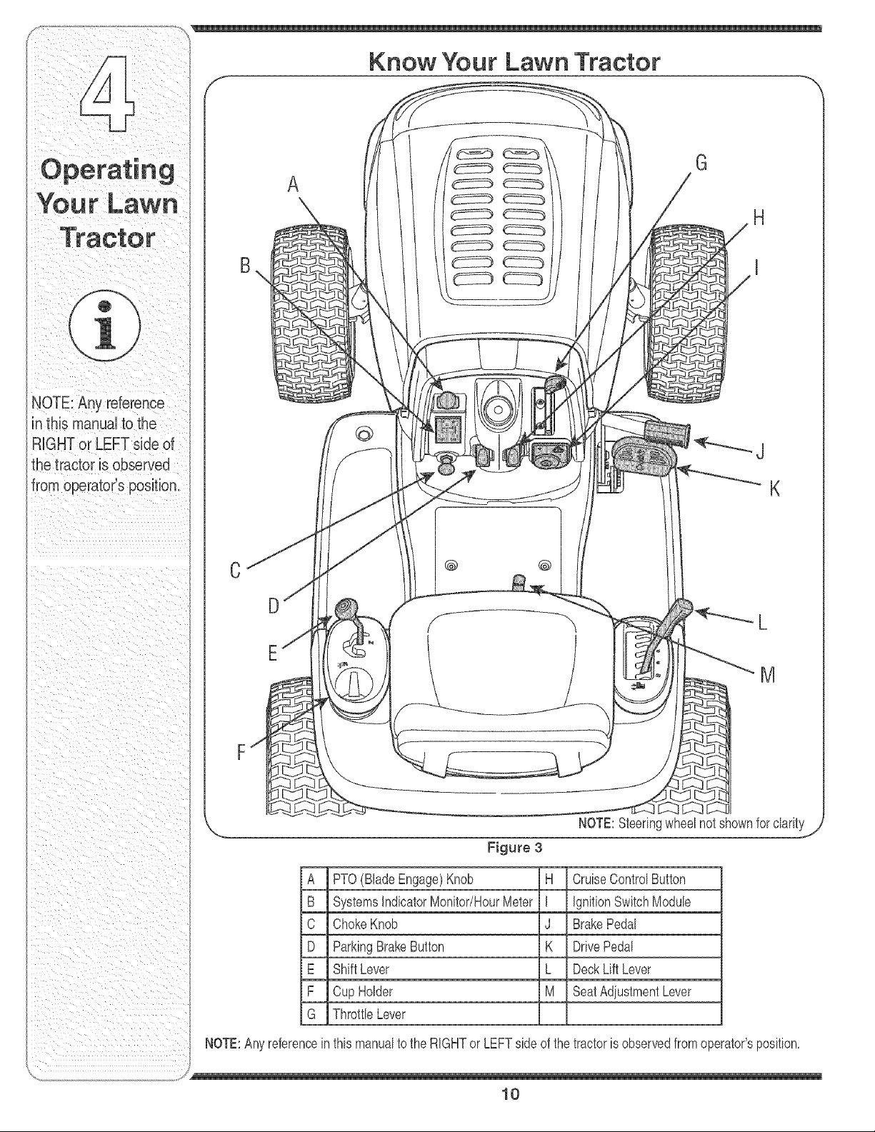
A
Know Your Lawn Tractor
G
@
@ @
J
K
M
A PTO(BladeEngage)Knob H CruiseControISutton
B SystemslndicatorMonitor/HourMeter I ignitionSwitchModule
C Choke Knob J BrakePedal
D ParkingBrakeButton K Drive Pedal
E ShiftLever L DeckLift Lever
F Cup Holder M SeatAdiustmentLever
G Throttb Lever
NOTE:Anyreferencein thismanualto the RIGHTor LEFTside of the tractoris observedfrom operator'sposition,
J
10
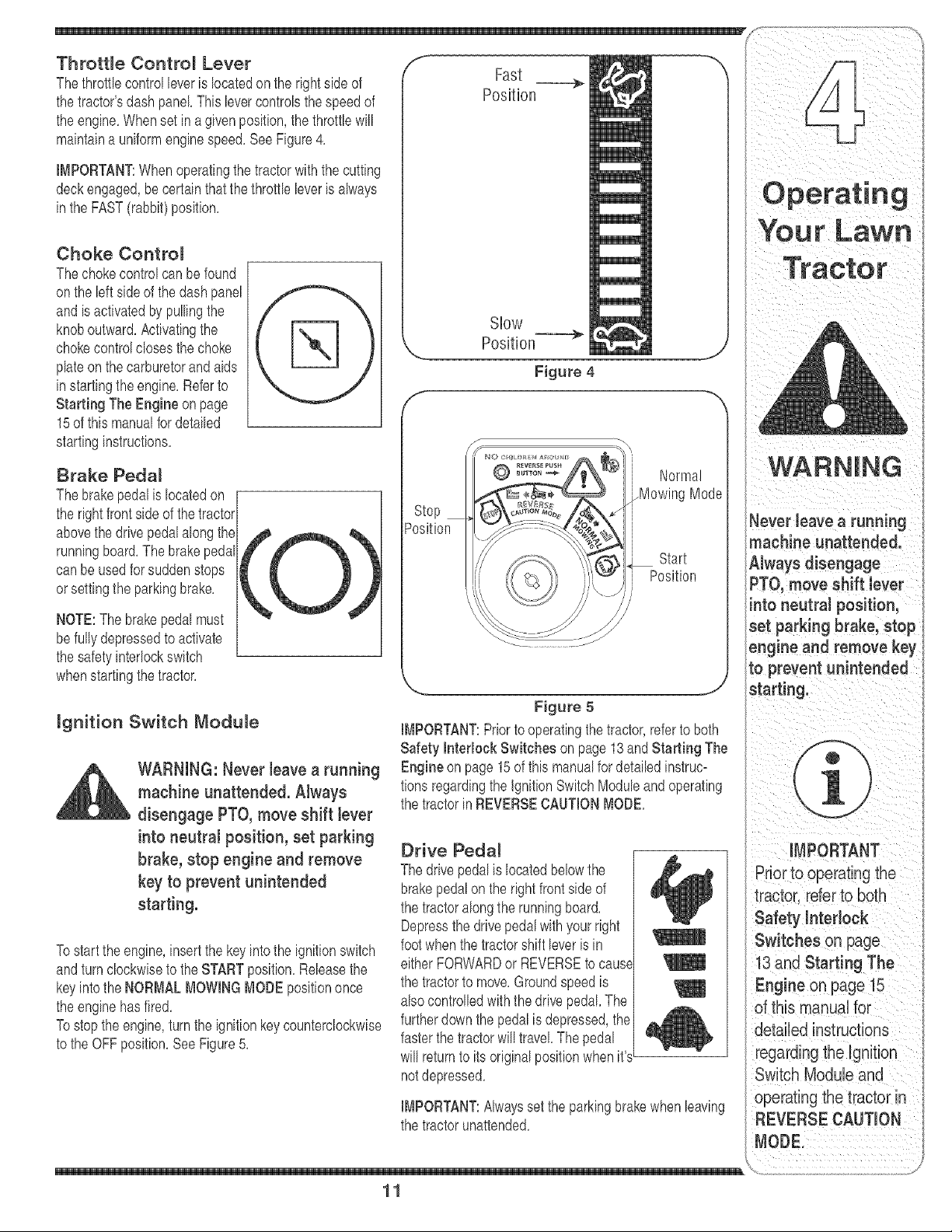
the engine.Whenset in a given position,the throttlewill
maintaina uniformenginespeed.SeeFigure4.
IMPORTANT:Whenoperatingthetractorwiththe cutting
deckengaged,be certainthat the throttb bver is always
inthe FAST(rabbit)position.
Choke Contro_
Thechokecontrolcan be found
onthe bft sideof the dashpanel
andis activatedby pullingthe
knoboutward.Activatingthe
chokecontrolclosesthe choke
plateonthe carburetorand aids
instartingthe engine.Referto
Starting The Engine onpage
15of this manualfordetailed
startinginstructions.
Brake Pedal
Thebrakepedalis locatedon [
the rightfront sideof thetractor/
abovethe drive pedalalongthe-
runningboard.The brakepedal
can be usedfor suddenstops
orsettingthe parkingbrake.
NOTE:The brakepedalmust
befully depressedto activate
the safetyinterlockswitch
whenstartingthetractor.
mgnition Switch Module
WARNING: Never have a running
machine unattended. AJways
disengage PTO, move shift bver
into neutral position, set parking
brake, stop engine and remove
key to prevent unintended
starting.
Tostartthe engine,insertthe keyintothe ignitionswitch
andturnclockwiseto theSTARTposition.Rebasethe
keyintothe NORMALMOWINGMODEpositiononce
the enginehasfired.
Tostopthe engine,turnthe ignitionkey counterclockwise
to the OFF position.See Figure5.
Slow
Position---=_
Figure 4
_osition
Normal
_MowingMode
Start
Position
Figure 5
IMPORTANT:Priorto operatingthe tractor,referto both
Safety hterlock Switches on page13andStarting The
Engineon page 15of this manualfordetailedinstruc=
tionsregardingthe ignitionSwitchModuleandoperating
the tractorin REVERSECAUTIONMODE.
Drive Pedal
The drivepedal is locatedbelowthe
brakepedalon the rightfront side of
the tractoralongthe runningboard.
Depressthe drivepedal with yourright
footwhenthe tractorshift bver is in
either FORWARDor REVERSEto cause
the tractorto move.Groundspeedis
also controlledwiththe drb'epedal.The
furtherdown the pedalis depressed,the
fasterthe tractorwill travel The pedal
will returnto its originalpositionwhen it'sL
notdepressed.
IMPORTANT:Alwaysset the parkingbrakewhenleaving
the tractorunattended.
11
machine unattended.
A ,vaysd sengage
PTO, move Shift lever
into neutral position,
set parking brake;stop
engineandremovekey
to prevent unintended
stai
operating the tractor in
REVERSE CAUTION
BATT, OIL
.ol
/// HOURS 1/10\\\
/
PTO/ BLADE PARKmNG
/
/
/
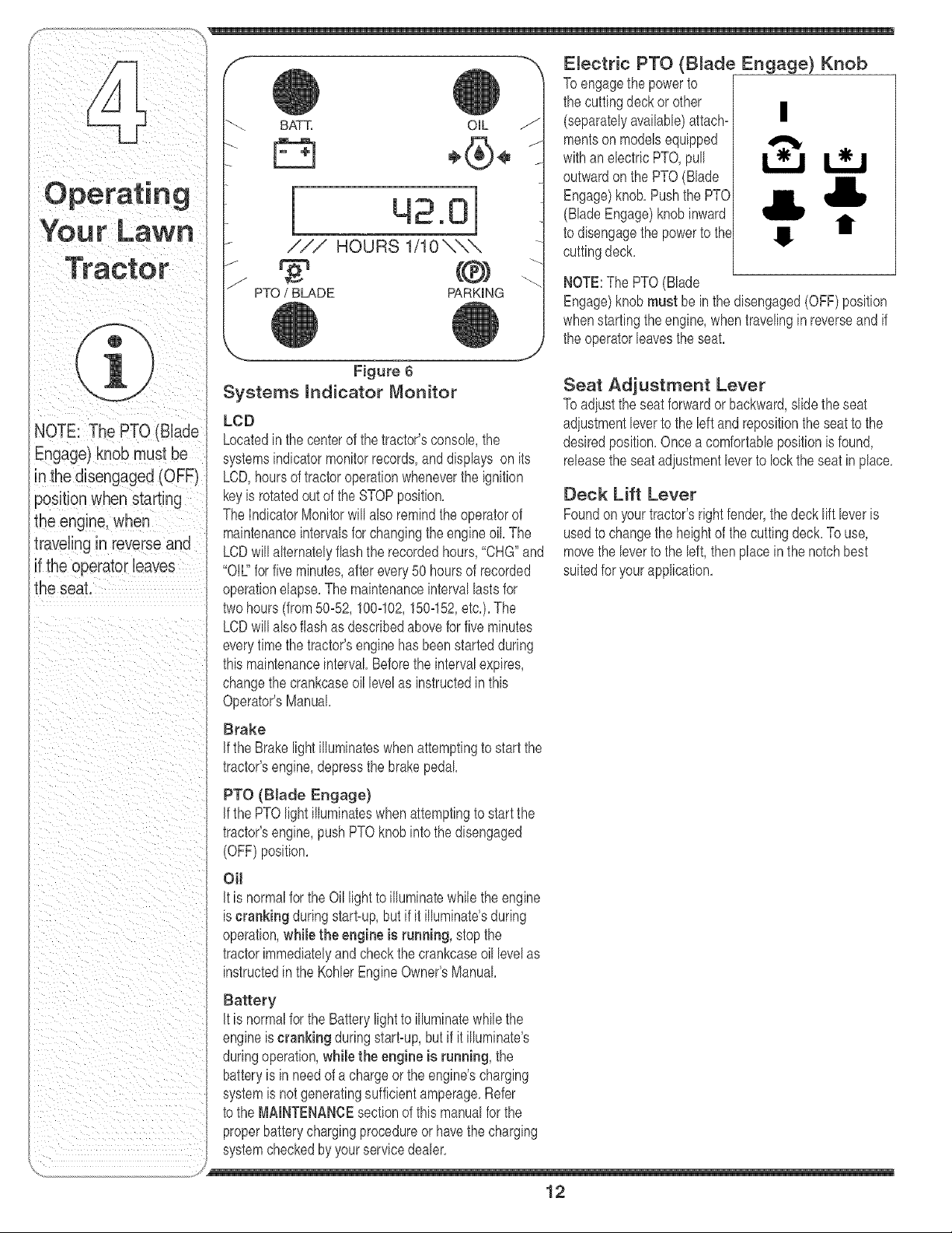
Electric PTO (B_ade Engage) Knob
Toengagethe powerto
the cuttingdeck or other
(separatelyavailable)attach- |
mentsonmodelsequipped
withanelectricPTO,pull
outwardon the PTO(Blade
Engage)knob,Pushthe PTO
(BladeEngage)knobinward
to disengagethe powerto the t
cuttingdeck,
I!
NOTE:The PTO(Blade
Engage)knob must be in the disengaged(OFF)position
whenstartingtheengine,whentravelingin reverseand if
the operatorleav'esthe seat,
NOTE:The PTo (Biade
Engage)knobmust be
inthedisengaged(OFF)
the seat.
Figure 6
Systems mndicator Monitor
LeD
Locatedinthe centerof the tractor'sconsole,the
systemsindicatormonitorrecords,anddisplays on its
LCD,hoursof tractoroperationwheneverthe ignition
keyb rotatedoutof the STOPposition,
The IndicatorMonitorwill also remindthe operatorof
maintenanceintervalsforchangingthe engineoil The
LCDwill alternatelyflashthe recordedhours,"CHG"and
"Oil" for five minutes,after every50 hoursof recorded
operationelapse,The maintenanceintervallastsfor
twohours(from50-52,100-102,150-152,etc,),The
LCDwill alsoflashas descrbed abovefor five minutes
everytimethe tractor'senginehasbeenstartedduring
thb maintenanceinterval Beforethe intervalexpires,
changethe crankcaseoil levelas instructedin this
Operator'sManual,
Brake
If the Brakelightilluminateswhenattemptingto start the
tractor'sengine,depressthe brakepedal
PTO (Blade Engage)
if the PTOlightilluminateswhenattemptingto start the
tractor'sengine,pushPTOknobinto thedisengaged
(OFF)position,
OH
it is normalforthe Oil lightto illuminatewhile theengine
is cranking duringstart-up,but if it illuminate'sduring
operation,while the engine is running, stopthe
tractorimmediatelyandcheckthe crankcaseoillevelas
instructedin the KohlerEngineOwner'sManual
Battery
it is normalforthe Batterylightto illuminatewhilethe
engineis cranking duringstart-up,but if it illuminate's
duringoperation,while the engine is running, the
batteryis in needof a chargeor the engine'scharging
systemis notgeneratingsufficientamperage,Refer
to the MAINTENANCEsectionof this manualfor the
properbatterychargingprocedureor havethe charging
systemcheckedby yourservmedealer,
Seat Adjustment Lever
Toadiustthe seat forwardor backward,slide the seat
adiustmentleverto the leftandrepositionthe seat to the
desiredposition,Oncea comfortabbposition isfound,
releasethe seat adiustmentleverto locktheseat inplace,
Deck Lift Lever
Foundon yourtractor'srightfender,thedecklift leveris
usedto changethe heightof the cuttingdeck,To use,
movethe bver to the left, thenplacein the notchbest
suitedfor yourapplication,
/
12
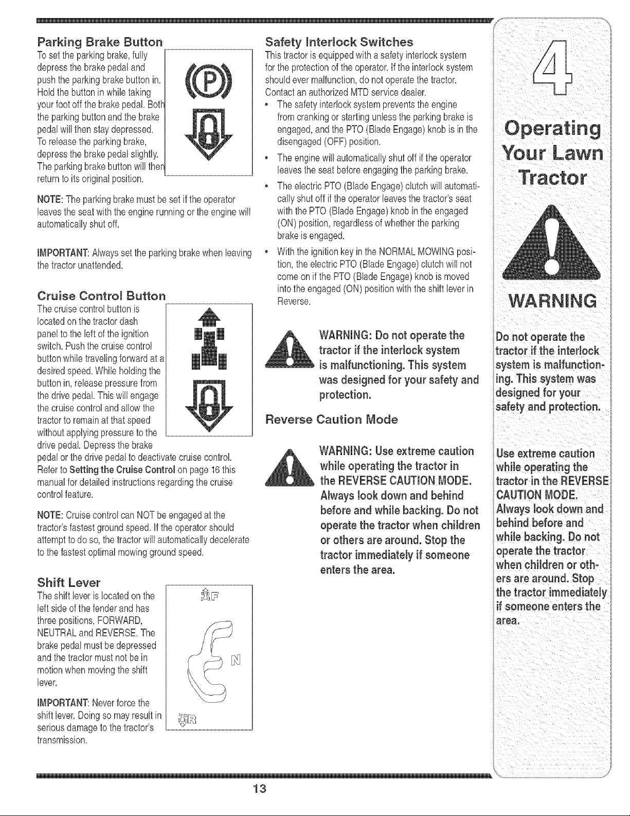
Parking Brake Button
Tosetthe parkingbrake,fully
depressthe brakepedaland
pushthe parkingbrakebutton in,
Holdthe button in whiletaking
yourfootoff thebrakepedal Both"
the parkingbuttonand the brake
pedalwill then staydepressed,
Toreleasethe parkingbrake,
depressthe brakepedalslightly,
Theparkingbrakebuttonwill ther
returnto its originalposition,
NOTE:The parkingbrakemustbesetif theoperator
leavesthe seatwith the engine runningor the enginewill
automaticallyshutoff,
IMPORTANT:Alwayssetthe parkingbrakewhen leaving
the tractorunattended,
Cruise Contro_ Button
Thecruisecontrolbuttonis
locatedonthe tractordash
panelto the left of the ignition
switch,Pushthe cruisecontrol
buttonwhiletravelingforwardat a
desiredspeed,While holdingthe
buttonin, releasepressurefrom
the drivepedal This will engage
the cruisecontroland allowthe
tractorto remainat thatspeed
withoutapplyingpressureto the
drivepedal Depressthe brake
pedalor the drivepedalto deactivatecruisecontrol
Referto Setting the Cruise Control on page16this
manualfor detailedinstructionsregardingthe cruise
controlfeature,
NOTE:Cruisecontrolcan NOTbe engagedat the
tractor'sfastestgroundspeed,if the operatorshould
attemptto do so, the tractorwill automaticallydecelerate
to the fastestoptimalmowinggroundspeed,
Shift Lever
Theshift leveris locatedon the
leftside of the fenderand has
threepositions,FORWARD,
NEUTRALand REVERSE,The
brakepedalmustbe depressed
andthe tractormustnot be in
motionwhenmovingthe shift
lever,
IMPORTANT:Neverforcethe
shift lever,Doingso may resultin
seriousdamageto the tractor's
transmission,
uu _
Thistractoris equippedwith asafetyinterlocksystem
for the protectionof the operator,If the interlocksystem
shouldevermalfunction,do notoperatethe tractor,
Contactan authorizedMTDservicedealer,
, The safetyinterlocksystempreventsthe engine
fromcrankingor startingunlessthe parkingbrakeis
engaged,and the PTO(Blade Engage)knob is in the
disengaged(OFF)position,
, The enginewill automaticallyshut off if the operator
leavesthe seat beforeengagingthe parkingbrake,
• The electricPTO(BladeEngage)clutch willautomati-
callyshutoff if the operatorleavesthetractor'sseat
withthe PTO(Blade Engage)knob in the engaged
(ON) position,regardlessof whetherthe parking
brakeis engaged,
, Withthe ignitionkey in the NORMALMOWINGposi-
tion,the electricPTO(Blade Engage)clutchwill not
comeonif the PTO(BladeEngage)knobis moved
into theengaged(ON) positionwith the shift leverin
Reverse,
WARNING: Do not operate the
tractor if the interlock system
is malfunctioning. This system
was designed for your safety and
protection.
Reverse Caution Mode
WARNING: Use extreme caution
while operating the tractor in
the REVERSE CAUTION MODE.
Always took down and behind
before and while backing. Do not
operate the tractor when children
or others are around. Stop the
tractor immediately if someone
enters the area.
13
Tractor
l
=aution
while operating the
tractor in the REVERSE
Always look down and
behind before and
whi!e back!rig, Donot
operate the tractor
when children or oth:
ers are around. Stop
the tractor immediately
if someone enters the
_,o iiiiiiiiiiiiiii _/
De not operate the
tractor if the interlock
system is malfunction-
ing. This system was
designed for your
safety and protection.
Position
Start
Position
J
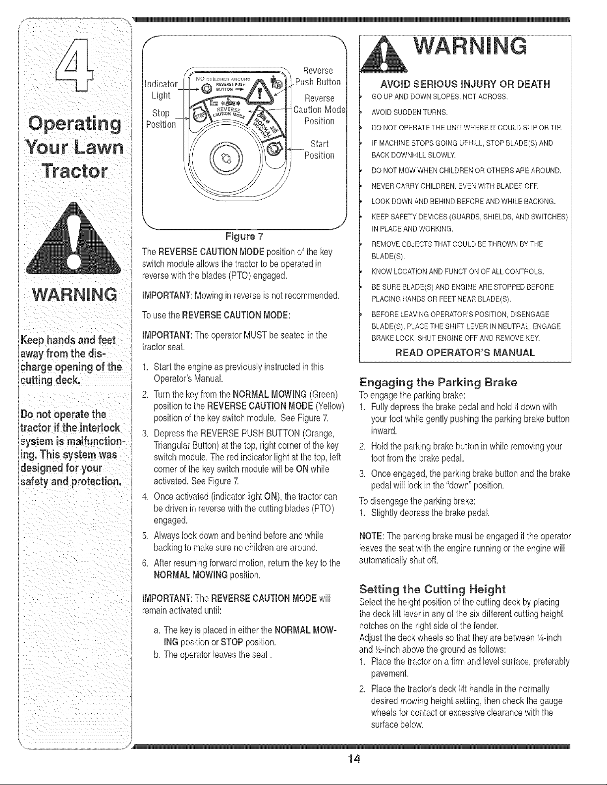
Figure 7
The REVERSECAUTIONMODEpositionof the key
switchmoduleallowsthe tractorto beoperatedin
reversewiththe blades(PTO)engaged,
IMPORTANT:Mowingin reverseis notrecommended,
Tousethe REVERSECAUTIONMODE:
IMPORTANT:The operatorMUSTbe seatedinthe
tractorseat,
1, Startthe engineas previouslyinstructedinthis
Operator'sManual
2, Turnthe key from the NORMALMOWING(Green)
positionto the REVERSECAUTIONMODE(Yellow)
positionof the key switchmodule, See Figure7,
3, Depressthe REVERSEPUSHBUTTON(Orange,
TriangularButton)at the top, rightcornerof the key
switchmodule,The red indicatorlight atthe top, left
cornerof the keyswitch modulewill be ON wMe
activated,SeeFigure7,
4, Onceactivated(indicatorlightON), thetractorcan
bedrivenin reversewiththe cuttingblades(PTO)
engaged,
5, AMayslook downand behindbeforeand wMe
backingto makesure no cMdren are around,
6, Afterresumingforwardmotion,returnthe keyto the
NORMALMOWINGposition,
IMPORTANT:The REVERSECAUTIONMODEwill
remainactivateduntil:
a, The keyis placedin eitherthe NORMALMOW-
INGpositionorSTOPposition,
b, Theoperatorleavesthe seat,
AVOIDSUDDENTURN&
DO NOT OPERATETHEUNITWHERE IT COULDSLIPORTIR
IFMACHINESTOPSGOINGUPHILL,STOP BLADE(S) AND
BACK DOWNHILLSLOWLY
DO NOT MOWWHEN CHILDRENOR OTHERSAREAROUND,
NEVER CARRYCHILDREN,EVENWITH BLADES OFE
LOOK DOWNAND BEHINDBEFOREAND WHILE BACKING.
KEEP SAFETY DEVICES(GUARDS,SHIELDS,AND SWITCHES
IN PLACEAND WORKING,
REMOVEOBJECTSTHATCOULDBE THROWNBYTHE
BLADE(Sb
KNOW LOCATIONAND FUNCTIONOF ALL CONTROLS.
BE SUREBLADE(S) AND ENGINEARESTOPPEDBEFORE
PLACINGHANDSORFEET NEAR BLADE(Sb
BEFORE LEAVINGOPERATOR'SPOSITION,DISENGAGE
BLADE(S), PLACETHE SHIFT LEVER IN NEUTRAL,ENGAGE
BRAKE LOCK, SHUT ENGINEOFF AND REMOVEKEY_
READ OPERATOR'S MANUAL
Engaging the Parking Brake
Toengagethe parkingbrake:
1, Fullydepressthe brakepedaland holdit downwith
yourfootwMe gently pushingthe parkingbrakebutton
inward,
2, Holdthe parkingbrakebutton in while removingyour
footfromthe brakepedal,
3, Onceengaged,theparkingbrakebuttonand the brake
pedalwill lock in the "down"position,
Todisengagethe parkingbrake:
1, Slightlydepressthe brakepedal
NOTE:The parkingbrakemustbeengagedif the operator
leavesthe seatwith the engine runningor the enginewill
automaticallyshutoff,
Setting the Cutting Height
Selectthe heightpositionof the cuttingdeck byplacing
the deck lift leverin anyof the six differentcuttingheight
notchesonthe rightsideof the fender,
Adjustthe deck wheelsso that theyare between_A=inch
and_/zqnchabovethe groundasfollows:
1, Placethetractoron a firmandlevelsurface,preferably
pavement,
2, Placethetractor'sdecklift handleinthe normally
desiredmowingheightsetting,thencheckthe gauge
wheelsfor contactor excessiveclearancewith the
surfacebelow,
J
14
iii ii it
if the wheelscontactthesurfaceadiustas follows: IMPORTANT:Do NOTholdthe key in the STARTpod=
3, Raisethe deck lift handleto its highestsetting,
4, Removethe reargaugewheelsbyremovingthe lock
nutsand shoulderscrewswhichsecurethem to the
deck,
5, Removethe locknutsand shoulderscrewswhich
securethe frontgauge wheelsto the deck,
6, Race thedeck lifthandle in the desiredmowing
heightsetting,
7, insertthe shoulderscrewwith the reargaugewheel
intothe indexhole that leavesapproximately1/2"
betweenthe bottomof the wheeland the pavement,
8, Notethe positionof the indexhole used; then install
the otherreargauge wheeland the frontball wheels
intothe correspondingindexholeof the othergauge
wheelbrackets,
9, if thegaugewheelshaveexcessiveclearancewith
the surfacebelow,lowerthe wheelsto the index
holethat providesthe approximate1/2" clearanceas
describedabove,
WARNING: Keep hands and feet
away from the discharge opening
of the cutting deck.
NOTE:The deckwheelsarean anti=scalpfeatureof the
deckand are notdesignedto supportthe weightof the
cuttingdeck,
tionfor longerthan ten secondsat a time, Doingso may
causedamageto yourengine'selectricstarter,
6, Afterthe enginestarts,deactivatethe chokecontrol
and placethethrottlecontrolin the FASTposition,
NOTE:DoNOTleavethe chokecontrolon whileoperat=
ingthe tractor,Doingso will result in a "rich"fuel mixture
andcausethe engineto run poorly,
Stopping the Engine
WARNING: if you strike a foreign
object, stop the engine, discon-
nect the spark plug wire(s) and
ground against the engine.
Thoroughly inspect the machine
for any damage. Repair the
damage before restarting and
operating
WARNING
1, Ifthe bladesare engaged,placethe PTO(Blade
Engage)knob in the disengaged(OFF)position,
2, Turnthe ignitionkeycounterclockwiseto the STOP
position,
3, Removethe key from the ignitionswitchto prevent
unintendedstarting,
Referto Leveling the Deck on page 18of this manual
for moredetailedinstructionsregardingvariousdeck
adiustments,
Starting the Engine
WARNING: Do not operate the
tractor if the interlock system is
malfunctioning. This system was
designed for your safety and
protection.
NOTE:Referto the TRACTORSET-UPon page8 of this
manualfor GasolineandOilfill=upinstructions,
1, insertthe tractorkey intothe ignitionswitch,
2, Race the PTO(BladeEngage)knobin the disem
gaged(OFF)position,
3, Engagethe tractor'sparkingbrake,
4, Activatethe chokecontrol,
5, Turnthe ignitionkeyclockwiseto the STARTposition,
Afterthe enginestarts, releasethe key,It will returnto
the ON position,
Driving The Tractor
WARNING: Avoid sudden starts,
ex-cessive speed and sudden
stops.
WARNING: Do not [cave the seat
of the tractor without first placing
the PTO (Blade Engage) knob in
the disengaged (OFF} position,
depressing the brake pedal and
engaging the parking brake. If
leaving the tractor unattended,
also turn the ignition key off and
remove the key.
1, Depressthe brakepedal to releasethe parkingbrake
and letthe pedalup,
2, Movethe throttleleverinto the FAST(rabbit)position,
15
Donotleavetheseat
Ofthetractorwithout
first placingthe PTO
(B!adeEngage)knobin
the disengaged (OFF)
position;depreSs, g
the brake pedal and
engaging the parking
brake. If leaving the
tractor unattended,
als0 turn the igaitio,
key off and remove the
key,
ii ii i
WARNING
Do not mow on inclines
with a slope in excess
of 15 degrees (a rise
of approximately 2-1/2
feet every 10feet). The
tractor could overturn
and cause serious
injury.
To help avoid blade
contact or a thrown
object injury, keep
bystanders, helpers,
children and pets at
least 75 feet from the
machine while it is in
operation. Stop rna=
chine if anyone enters
the area.
IMPORTANT:Do NOTusethe shift leverto changethe
directionof travelwhenthe tractoris in motion,Always
usethe brakepedalto bringthe tractorto a complete
stopbeforeshifting,
3, To moveforward,placethe shift leverin the
FORWARDposition,then slowlydepressthe drive
pedaluntilthe desiredspeedis achieved,
4, To movein reverse,placetheshift leverin the
REVERSEposition,check thattheareabehindis
clearthenslowlydepressthe drivepedal,
Driving On S_opes
Referto the SLOPEGAUGEon page3 to helpdeter=
mineslopeswhereyou mayoperatethe tractorsafely,
WARNING: Do not mow on
inclines with a stope in excess
of 15 degrees (a rise of approxi-
mately 2-1/2 feet every 10feet).
The tractor could overturn and
cause serious injury.
Mowupanddownslopes,NEVERacross,
Exerciseextremecautionwhenchangingdirection
onslopes,
, Watchfor holes, ruts,bumps,rocks, or otherhidden
obiects,Uneventerraincouldoverturnthe machine,
Tall grasscan hide obstacles,
, Avoidturnswhendrivingona slope, If a turn must
be made,turn downthe slope,Turningup a slope
greatlyincreasesthechanceof a rollover,
, Avoidstoppingwhendrivingupa slope, If it is
necessaryto stopwhiledrivingupa slope,start up
smoothlyandcarefullyto reducethe possibilityof
flippingthetractoroverbackward,
Setting The Cruise Control
1, Placethe shiftleverin the FORWARDposition,
thenslowlydepressthedrive pedal untilthedesired
speedis achieved,
2, Lightlydepressthe cruisecontrol button,
3, While continuingto hold the cruisebuttonin, liftyour
footfrom thedrive pedal(youshouldfeel thecruise
latchengage),
Onceengaged,thecruise controlbuttonand thedrive
pedalwill lockin the "down"position,and thetractorwill
maintainthe sameforwardspeed,
NOTE:Cruisecontrolcan not be engagedat the tractor's
fastestgroundspeed,If theoperatorshouldattemptto do
so,the tractorwillautomaticallydecelerateto the fastest
optimalmowinggroundspeed,
Disengagethecruisecontrolusingoneof the following
methods:
1, Depressthe brakepedalto disengagethecruise
controlandstop the tractor,
2, Lightlydepressthe drivepedal
Tochangeto the reversedirectionwhenoperatingwith
cruisecontrol,depressthe brakepedalto disengagethe
cruisecontroland bringthe tractorto a completestop,
Thenplacethe shift leverin the REVERSEpositionand
depressthe drive pedal
Engaging the B_ades
Engagingthe PTO(Blade Engage)transferspowerto the
cuttingdeckor other (separatelyavailaNe)attachments,
Toengagethe blades,proceedas follows:
1, Movethe throttlecontrolleverto the FAST(rabbit)
position,
2, Pullthe PTO(BladeEngage)knoboutwardintothe
engaged(ON) position,
3, Keepthe throttleleverin the FAST(rabbit)position
for the mostefficientuseof the cuttingdeck or other
(separatelyavailable)attachments
iMPORTANT:Theelectric PTOclutchwill automatically
shutoff if the PTOis engagedwith the shift leverin posi=
tionfor reversetravelwiththe ignitionkey in the NORMAL
MOWINGposition,Referto SafetyInterlockSwitcheson
page13,
Using the Deck Lift Lever
Toraisethe cuttingdeck, movethe deck lift leverto the
left, thenplace it in the notch bestsuited for yourapplica-
tion,Referto SettingThe CuttingHeightearlierin this
section,
Mowing
WARNING: To help avoid blade
contact or a thrown object injury,
keep bystanders, hetpers, children
and pets at least 75 feet from the
machine while it is in operation.
Stop machine if anyone enters the
area.
y
16
Thefollowinginformationwill be helpfulwhenusingthe
cuttingdeckwith yourtractor:
WARNING: Plan your mowing
pattern to avoid discharge of
matedaJs toward roads, side°
waJks, bystanders and the Jike.
Nso, avoid discharging materiaJ
against a wall or obstruction
which may cause discharged
matedaJ to ricochet back toward
the operator.
Operatin
Your Lawn
Do not mowat high groundspeed,especiallyif a
mulchkit or grasscollectoris installed,
• For bestresultsit is recommendedthat the firsttwo
lapsbe cutwith the dischargethrowntowardsthe
center,Afterthefirst two laps, reversethe directionto
throwthe dischargeto the outsidefor the balanceof
cutting,Thiswill givea betterappearancetothe lawn,
• Do notcut thegrass too short,Shortgrass invites
weedgrowthandyellowsquicklyin dryweather,
• Mowingshouldalwaysbedone with theengineat full
throttle,
• Underheavierconditionsit may be necessarytogo
backover thecut areaa secondtime to get a clean
cut,
, Do NOTattemptto mow heavybrushand weedsand
extremelytall grass,Yourtractoris designedto mow
lawns,NOTclearbrush,
• Keepthe bladessharpand replacethe bladeswhen
worn,RefertoCutting Blades onpage22 of this
manualfor properbladesharpeninginstructions,
MuJching (If Equipped)
Selectmodelscomeequippedwith a mulch kit which
incorporatespecialblades,alreadystandardon the
tractor,ina processof recirculatinggrassclippings
repeatedlybeneaththecutting deck,The ultra-fine
c@pingsarethenforced backinto thelawnwherethey
actas a naturalfertilizer,
Observethe followingpointsfor the best resultswhen
mulching:
, Neverattemptto mulchif the lawnis damp,Wet grass
tendsto stick to the undersideof the cuttingdeck
preventingpropermulchingof the c@pings,
• Do NOTattemptto mulch morethan 1/3the total
heightof thegrass or approximately14/2 inches,
Doingso will causethe clippingsto clump up beneath
the deck and not be mulchedeffectively,
Figure 8
Maintaina slowgroundspeedto allowthegrass
clippingsmoretimeto effectivelybe mulched,
Alwayspositionthe throttlecontrolleverin the FAST
(rabbit)positionandallow it to remaintherewhile
mowing,Failingto keepthe engineat full throttle
placesstrainon thetractor'sengineanddoes not
allow thebladesto properlymulchgrass,
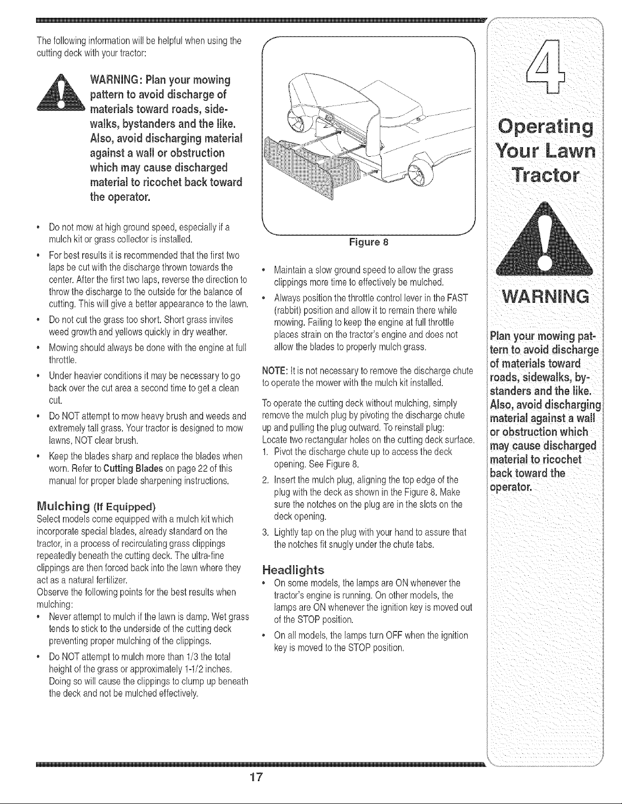
NOTE:Itis not necessaryto removethe dischargechute
tooperatethe mowerwith the mulchkit installed,
To operatethe cuttingdeck withoutmulching,simply
removethe mulchplugby pivotingthe dischargechute
upand pullingthe plug outward,Toreinstallplug:
Locatetworectangularholeson the cuttingdeck surface,
1, Pivotthe dischargechute up to accessthe deck
opening,SeeFigure8,
2, Insertthe mulchplug,aligningthe topedge of the
plugwiththe deck as shownin the Figure8, Make
sure the notcheson the plug are in theslots on the
deckopening,
3, Lightlytap on the plug with yourhandto assurethat
the notchesfit snugly underthe chutetabs,
Headlights
• On somemodels,the lampsare ON wheneverthe
tractor'sengineis running,Onothermodels,the
lampsareON wheneverthe ignitionkeyis movedout
of the STOPposition,
, On all models,the lampsturnOFF whenthe ignition
keyis movedto the STOPposition,
17
tern to avoid discharge
of materials toward
roads, sidewalks, by-
standers and the like.
AJso, avoid discharging
materiaJ against a wall
or obstruction which
may cause discharged
materiaJ to ricochet
back toward the
operator.
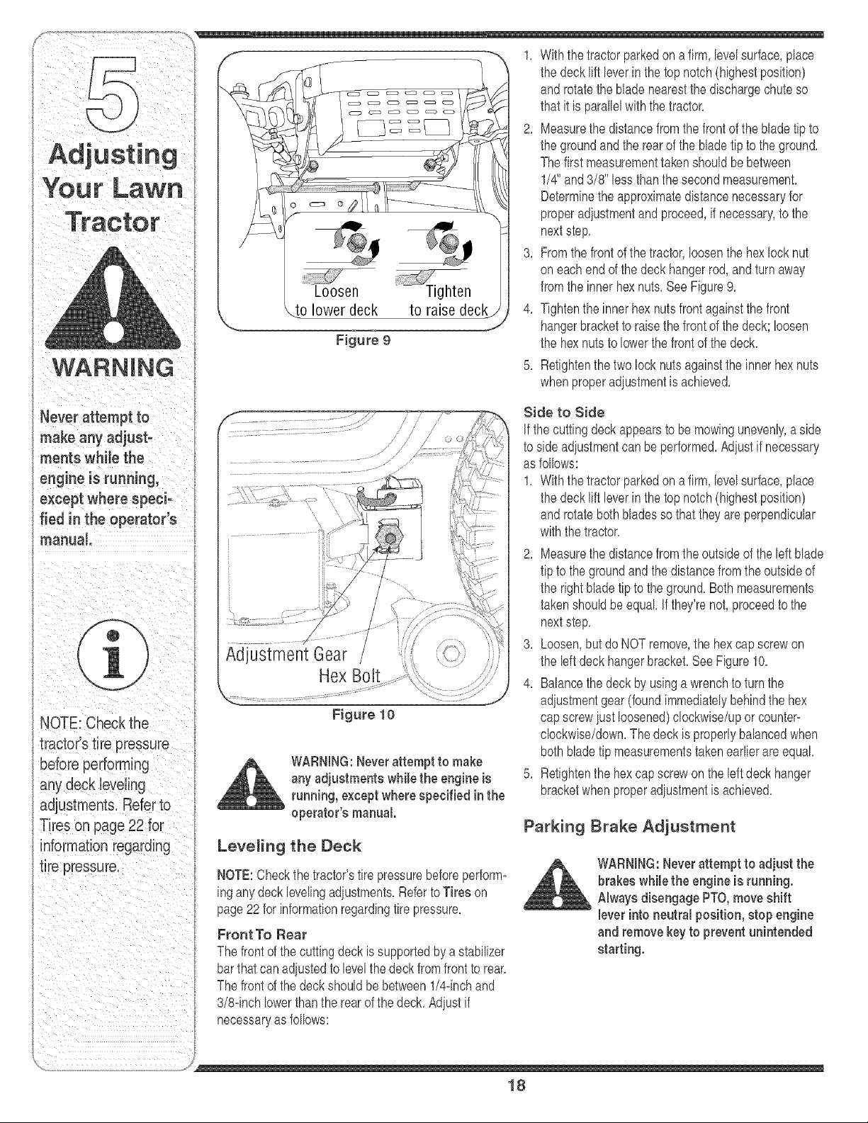
Loosen
lower deck
Figure 9
Figure 10
WARNING:Neverattempt to make
any adjustments while the engine is
running, except where specified in the
operator's manual.
Leveling the Deck
NOTE:Checkthe tractor'stire pressurebeforeperform-
ingany deck levelingadiustments,Referto Tires on
page22 for informationregardingtire pressure,
Front To Rear
The front of the cuttingdeck is supportedbya stabilizer
barthatcan adiustedto levelthe deck from front to rear,
The front of the deck shouldbe between1/4-inchand
3/8-inchlowerthanthe rear of thedeck, Adjustif
necessaryas follows:
Thefirst measurementtakenshouldbe between
1/4" and3/8" lessthanthe secondmeasurement,
Determinethe approximatedistancenecessaryfor
properadiustmentandproceed,if necessary,to the
nextstep,
3, Fromthe front of thetractor,loosenthe hexlock nut
oneachend of thedeck hangerrod, and turnaway
fromthe innerhex nuts,See Figure9,
4, Tightenthe innerhex nutsfront againstthe front
hangerbracketto raisethe front of the deck; loosen
the hexnuts to lowerthe frontof thedeck,
5, Retightenthe two lock nutsagainstthe inner hexnuts
whenproperadiustmentis achieved,
Side to Side
if thecutting deckappearsto be mowingunevenly,a side
to sideadiustmentcan be performed,Adiustif necessary
as follows:
1, Withthetractor parkedon a firm,levelsurface,place
the deck lift leverin the top notch(highestposition)
androtate bothbladesso that they are perpendicular
withthe tractor,
2, Measurethe distancefromthe outsideof the left blade
tip to the groundand the distancefrom theoutsideof
the rightblade tipto the ground,Bothmeasurements
takenshouldbeequal If they'renot,proceedto the
nextstep,
8, Loosen,butdo NOTremove,the hexcap screwon
the left deck hangerbracket,See Figure10,
4, Balancethe deck by usinga wrenchto turnthe
adiustmentgear(foundimmediatelybehind the hex
capscrewiust loosened)clockwise/uporcounter-
clockwise/down,Thedeckis properlybalancedwhen
both bladetip measurementstakenearlierare equal
5, Retightenthe hex capscrewon the bft deckhanger
bracketwhenproperadiustmentis achieved,
Parking Brake Adjustment
WARNING:Neverattempt to adjust the
brakes while the engine is running.
Always disengage PTO, move shift
lever into neutral position, stop engine
and remove keyto prevent unintended
starting.
18
if the tractordoesnot cometo a compbte stop whenthe
brakepedalis completelydepressed,or if the tractor's
rearwheelscan roll with the parkingbrakeapplbd, the
brakeis inneedof adiustment,The brakedisc can be
foundon the rightsideof the transmissionin the rearof
the tractor,Adiustif necessaryas follows:
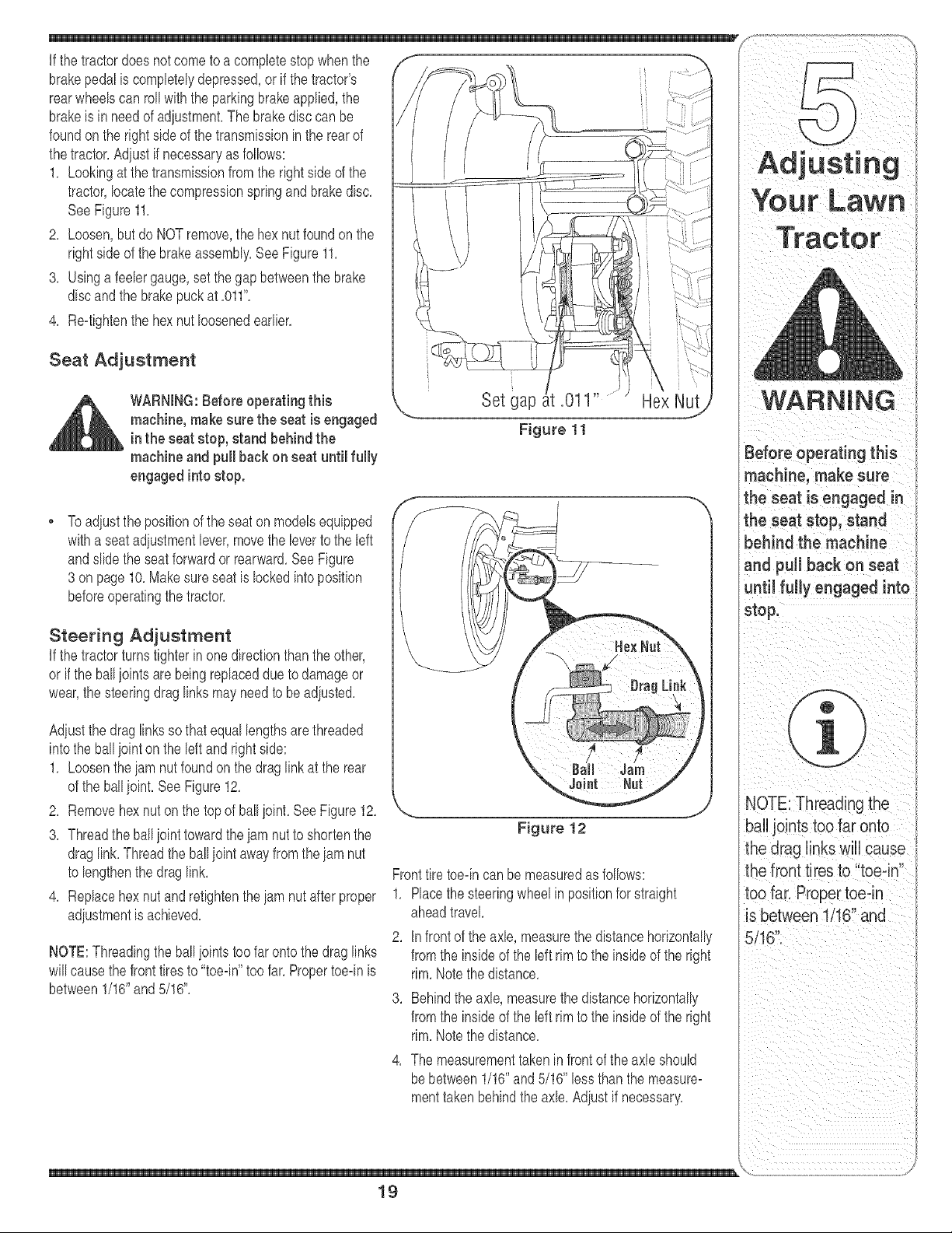
1, Lookingat thetransmissionfrom the rightside of the
tractor,locatethe compressionspringand brakedisc,
SeeFigure11,
2, Loosen,but do NOTremove,the hex nutfoundon the
rightsideof the brakeassembly,See Figure11,
3, Usinga feebr gauge,set the gap betweenthe brake
discandthe brakepuck at ,011",
4, Reqightenthe hexnut loosenedearlier,
Seat Adjustment
_ ARNING: Before operating this
machine, make sure the seat is engaged
in the seat stop, stand behind the
machine and pull back on seat until fully
engagedinto stop.
Set gap .011
Figure 11
Hex Nut
To adiustthe positionof theseat on modelsequipped
witha seatadiustmentlever,movethe bv'erto the left
andslide the seatforwardor rearward.See Figure
3 on page10.Makesureseat is lockedintoposition
beforeoperatingthe tractor.
Steering Adjustment
if the tractorturnstighter in one directionthan theother,
or if the ball ioints are being replaceddue to damageor
wear,the steeringdrag linksmay need to be adiusted,
Adiustthedrag links so that equal bngths are threaded
into the ball iointon the left and right side:
1, Loosentheiam nut foundon the drag linkat the rear
of the ballioint, See Figure12,
2, Removehex nuton the topof ballioint, See Figure12,
3, Threadthe ballioint towardtheiam nutto shortenthe
draglink, Threadthe ballioint awayfrom theiam nut
to bngthenthe drag link,
4, Replacehex nutand retightentheiam nut after proper
adiustmentis achieved,
NOTE:Threadingthe ballioints too far ontothe drag links
will causethe front tires to "toe4n"too far,Propertoeqn is
between1/16"and5/16",
Figure 12
NOTE: Threading the
Fronttire toeqncan be measuredas follows:
1, Placethesteeringwheelin positionfor straight
aheadtravel
2, In front of the axle, measurethe distancehorizontally
fromthe insideof the left rimto the insideof the right
rim,Notethedistance,
3, Behindthe axle, measurethe distancehorizontally
fromthe insideof the left rimto the insideof the right
rim,Notethedistance,
4. Themeasurementtakeninfr_nt_ftheaxIe_h_uIdbebetween1/16__and5/16Èbssthanthemeasure_
menttakenbehindtheaxle,Adiustifnecessary, L
19
inorder te rep!acethe
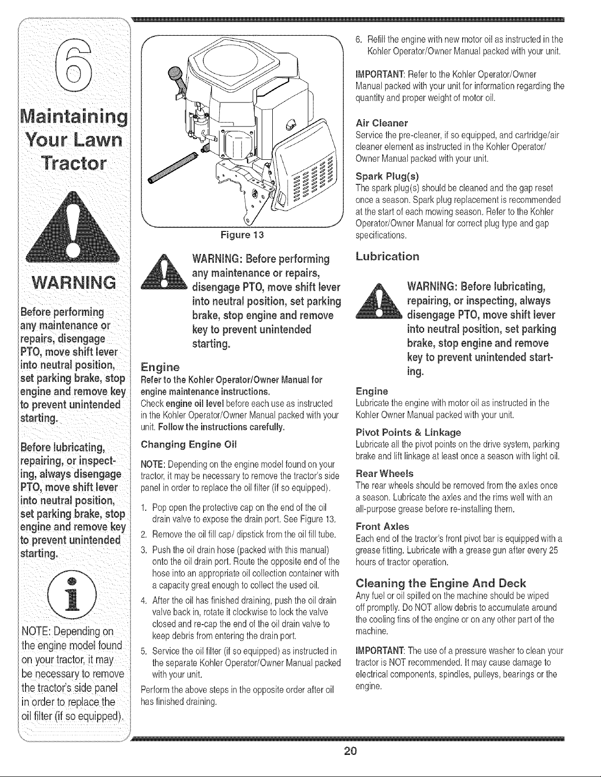
Figure 13
WARNING: Before performing
any maintenance or repairs,
disengage PTO, move shift lever
into neutral position, set parking
brake, stop engine and remove
key to prevent unintended
starting.
Engine
Referto the Kohler OperatodOwner Manual for
engine maintenance instructions.
Checkengine oil level beforeeachuseas instructed
in the Kohbr Operator/OwnerManualpackedwith your
unit,Follow the instructionscarefully.
Changing Engine Oil
NOTE:Dependingonthe engine modelfoundon your
tractor,it may be necessaryto removethe tractor'sside
panelin order to replacethe oil filter (if so equipped),
1, Popopenthe protectivecap onthe endof the oil
drainvalveto exposethe drainport, See Figure13,
2, Removetheoil fill cap/dipstick fromthe oil fill tube,
3, Pushthe oil drain hose(packedwith this manual)
ontothe oil drain port, Route theoppositeend of the
hoseintoan appropriateoil colbction containerwith
a capacitygreatenoughto colbct the usedoil
4, Aftertheoil has finisheddraining,pushtheoil drain
valvebackin, rotateit clockwiseto lock the valve
closedandre=capthe end of the oil drainvalve to
keepdebrisfromenteringthedrainport,
5, Servicethe oil filter (if soequipped)as instructedin
the separateKohbr Operator/OwnerManualpacked
withyourunit,
Performthe abovestepsinthe oppositeorder afteroil
hasfinisheddraining,
6, Refillthe enginewith newmotoroil as instructedin the
KohlerOperator/OwnerManualpackedwithyour unit,
IMPORTANT:Referto the KohlerOperator/Owner
Manualpackedwithyourunit for informationregardingthe
quantityand properweightof motoroil
Air Cleaner
Servicethe pre=cbaner,if so equipped,and cartridge/air
cbaner elementas instructedin the Kohbr Operator/
OwnerManualpackedwithyour unit.
Spark PJug(s)
Thesparkplug(s)shouldbecleanedand the gap reset
oncea season,Sparkplug replacementis recommended
at the startof each mowingseason,Referto the Kohbr
Operator/OwnerManualfor correctplugtype and gap
specifications,
Lubrication
WARNING: Before lubricating,
repairing, or inspecting, atways
disengage PTO, move shift lever
into neutral position, set parking
brake, stop engine and remove
key to prevent unintended start-
ing.
Engine
Lubricatethe enginewith motoroil as instructedin the
KohlerOwnerManualpackedwith yourunit,
Pivot Points & Linkage
Lubricateall the pivotpointson the drivesystem,parking
brakeandlift linkageat bast oncea seasonwithlightoil
Rear Wheels
The rearwheelsshouldbe removedfrom the axles once
a season,Lubricatethe axles and the rimswell with an
all=purposegreasebeforere=installingthem,
Front AxJes
Eachendof the tractor'sfrontpivotbaris equippedwith a
greasefitting,Lubricatewitha greasegun afterevery25
hoursof tractoroperation,
Cleaning the Engine And Deck
Anyfuel or oil spilledon the machineshouldbe wiped
off promptly.DoNOTallowdebristo accumulatearound
the coolingfins of the engine or on anyotherpart of the
machine.
IMPORTANT:The useof a pressurewasherto cban your
tractoris NOTrecommended,It maycausedamageto
ebctrbal components,spindles,pulleys,bearingsor the
engine,
2O
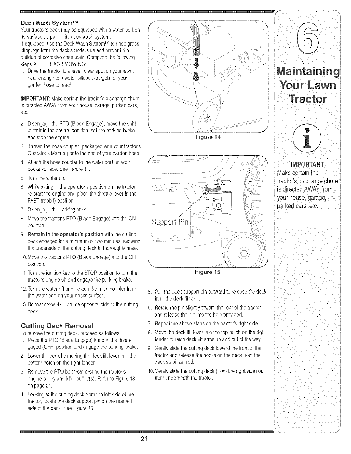
Deck Wash System TM
Yourtractor'sdeckmay'beequippedwitha waterport on \,
itssurfaceas part of its deck wash system,
If equipped,usethe DeckWashSystemTM to rinsegrass
clippingsfromthe deck'sundersideandpreventthe
buildupof corrosivechemicals,Completethe following
stepsAFTEREACHMOWING:
1, Drivethe tractorto a level,clearspot on yourlawn,
nearenoughto a water sillcock(spigot)for your
gardenhoseto reach,
IMPORTANT:Makecertainthetractor'sdischargechute
is directedAWAYfromyourhouse,garage,parkedcars,
etc,
2, Disengagethe PTO(BladeEngage),movethe shift
leverintothe neutralposition,set the parkingbrake,
andstop theengine,
3, Threadthe hosecoupler(packagedwith yourtractor's
Operator'sManual)ontothe endof yourgardenhose,
4, Attachthe hosecouplerto the waterport on your
deckssurface,SeeFigure14,
5, Turnthe wateron,
6, Whilesittingin theoperator'spositionon thetractor,
re=startthe engineandplacethe throttleleverin the
FAST(rabbit)position,
7, Disengagethe parkingbrake,
8, Movethe tractor'sPTO(BladeEngage)intothe ON
position,
9, Remaininthe operator's position with the cutting
deckengagedfor a minimumof two minutes,allowing
the undersideof thecuttingdeck to thoroughlyrinse,
10,Movethe tractor'sPTO(BladeEngage)intothe OFF
position,
11,Turnthe ignitionkeyto the STOPpositionto turn the
tractor'sengineoff andengagethe parkingbrake,
12,Turnthe wateroff anddetachthe hosecouplerfrom
the waterport on yourdeckssurface,
13,Repeatsteps4=11on theoppositeside of thecutting
deck,
Cutting Deck Remova_
Toremovethe cuttingdeck, proceedas follows:
1, Placethe PTO(BladeEngage)knobin the disen=
gaged(OFF)positionand engagethe parkingbrake,
2, Lowerthe deckby movingthedeck lift leverinto the
bottomnotchon the rightfender,
3, Removethe PTObeltfromaroundthe tractor's
enginepulleyandidler pulley(s),Referto Figure18
onpage 24,
4, Lookingat the cuttingdeck fromthe left sideof the
tractor,locatethe decksupport pin on the rearleft
sideof the deck, See Figure15,
i
i "\
Figure 14
Support Pin
...... ............. i / / /
Figure 15
5, Pullthe deck support pin outwardto releasethe deck
fromthe deck lift arm,
6, Rotatethe pin slightlytowardthe rearof the tractor
and releasethe pin intothe holeprovided,
7, Repeatthe abovestepson the tractor'srightside,
8, Movethe deck lift leverinto thetop notchon the right
fenderto raisedeck lift arms up and out of the way,
9, Gentlyslidethe cuttingdeck towardthe front of the
tractorand releasethe hookson the deck from the
deckstabilizerrod,
10,Gentlyslidethe cuttingdeck (fromthe rightside) out
from underneaththe tractor,
21
iMPORTANT
Make certain the
tractor's discharge chute
is directed AWAYfrom
your house garage,
parked cars. etc.
WARNING
Never exceed the
maximum inflation
_ressureshown on the
sidewall of the tire.
Batteries g ive off an
.=×plosivegas whib
:barging. Charge bat-
tery in a wellventiJated
_rea and keep away
from an open flame
_r pilot light as on a
_vaterheater, space
heater, furnace, clothes
;lryeror other gas
_ppliances.
Be sure to shut the
engine off, remove
ignition key, discon-
nect the spark plug
wire(s) and ground
against the engine to
prevent unintended
starting before remov=
ing the cutting blade(s)
for sharpening or
replacement. Protect
your hands by using
heavy gloves or a rag
tograsp the cutting
blade.
Jump Starting
WARNING: Never e×ceed the
ma×imum inflation pressure
shown on the sidewall of tire.
The recommendedoperatingtire pressureis:
Approximately10psifor the reartires
Approximately14psi for the fronttires
IMPORTANT:Referto the tire sidewallforexacttire
manufacturer'srecommendedormaximumpsi. Do not
overinflate.Uneventire pressurecouldcausethe cutting
deckto mow unevenly.
Battery
Thebatteryis seabd and is maintenance-free.Acid
bvels cannotbe checked.
. Alwayskeepthe batterycabbs and terminalscban
andfreeof corrosivebuild-up.
. Aftercleaningthe batteryand terminals,apply a light
coatof petroleumielly or greaseto bothterminals.
• Alwayskeepthe rubberboot positionedoverthe
positiveterminalto preventshorting.
IMPORTANT:If removingthe batteryforany reason,
disconnectthe NEGATIVE(Black)wire fromit's terminal
first,followedbythe POSITIVE(Red)wire.When
re-installingthe battery,alwaysconnectthe POSITIVE
(Red)wire itsterminalfirst,followedbythe NEGATIVE
(Black)wire.Becertainthat thewiresare connectedto
thecorrectterminals;reversingthemcould changethe
polarityandresult in damageto your engine'salternat-
ingsystem.
Charging
If thetractor hasnot beenput into usefor an extended
periodof time,chargethe batterywith an automotive-
type 12-voltchargerfor a minimumof one hour at six
ampe.
WARNING: Batteries give off an
explosive gas while charging.
Charge battery in a well venti-
lated area and keep away from
an open flame or pilot light as
on a water heater, space heater,
furnace, clothes dryer or other
gas appliances.
WARNING: When removing or
installingthe battery, follow
these instructions to prevent the
screwdriver from shorting against
the frame.
IMPORTANT:Neveriumpyourtractor'sdeadbatterywith
the batteryof a runningvehicle,
1. Connectendof one iumpercableto the positive
terminalof thegood battery,thenthe otherend to the
positiveterminalof the dead battery.
2. Connectthe otheriumpercableto the negative
terminalof thegood battery,thento the frame of the
unit with the dead battery.
WARNING: Failure to use this
procedure could cause sparking,
and the gas in either battery could
explode.
Cleaning
Cban the batteryby removingit fromthe tractorand
washingwitha bakingsodaandwatersolution,if neces-
sary,scrapethe batteryterminalswith a wire brushto
removedeposits,CoatterminaBandexposedwiringwith
greaseor petroleumielly to preventcorrosion,
Battery Failures
Somecommoncausesfor batteryfailureare:
. incorrectinitialactivation • undercharging
. overcharging • corrodedconnections
"freezing
Thesefailures are NOTcovered by your tractor's
warranty.
Cutting B_adee
WARNING: Be sure to shut the
engine off, remove ignition
key, disconnect the spark plug
wire(s) and ground against the
engine to prevent unintended
starting before removing the
cutting blade(s) for sharpening or
replacement. Protect your hands
by using heavy gloves or a rag to
grasp the cutting blade.
22

WARNING:Periodicallyinspect
the Made spindJes for cracks or
damage, especially if you strike a
foreign object. Replace immedi-
ately if damaged.
Thebladesmayberemovedas follows,
1, Removethe deck from beneaththe tractor,(referto
CuttingDeckRemovalon page21)thengently flip
the deck overto exposeits underside,
2, Race a blockof wood betweenthe centerdeck hous-
ingbaffleand the cuttingbladeto act asa stabilizer,
SeeFigure16,
3, Usea 15/16"wrenchto removethe hexflangenut
thatsecuresthe bladeto thespindleassembly,See
Figure16,
4, Toproperlysharpenthe cutting blades,removeequal
amountsof metalfrom bothends of the bladesalong
the cuttingedges, parallelto the trailingedge,at a
25° to 30° angle,
I[_tPORTANT:If the cuttingedgeof the blade hasalready
beensharpenedto within 1 5/8" fromthe edge,or if any
metalseparationis present,replacethe bladeswith new
ones,See Figure17,
It is importantthateachcuttingblade edge be ground
equallyto maintainproperbladebalance,
• A poorlybalancedbladewill causeexcessive
vibrationand maycausedamageto thetractorand
resultinpersonalinjury,The bladecan be testedby
balancingit on a roundshaftscrewdriver,Grindmetal
fromthe heavysideuntil it balancesevenly,
• Whenreplacingthe blade,be sureto installthe blade
withthe sideof the blade marked"Bottom" (orwith
a part numberstampedin it) facingthe groundwhen
the moweris in the operatingposition,
IMPORTANT:Usea torquewrenchto tightenthe blade
spindlehexflangenutto between70foot-poundsand 90
foot-pounds,
Fuses
A fuseis installedin yourtractor'swiringharnessto
protectthe tractor'selectricalsystemfromdamage
causedby excessiveamperage,
Figure 16
Figure 17
If the electricalsystemdoes notfunction,or your
tractor'senginewill notcrank,first checkto becertain
thatthe fuse has not blown,
• It can eitherbe foundunderthe hoodmountedbehind
the top of the dashpanelon the supportbar,or under
the seat mountedto the insideof the tractorframe
nextto the batterytray,
Always use a fuse with the same
amperage capacity for replace-
meat.
23
Periodically inspect
the blade spindles for
cracks or damage,
especially if you strike
a foreign object.
Replace immediately if
damaged.
Always use a fuse with
:he same amperage
capacity for replace-
meat.
f_!!_ _i_ _
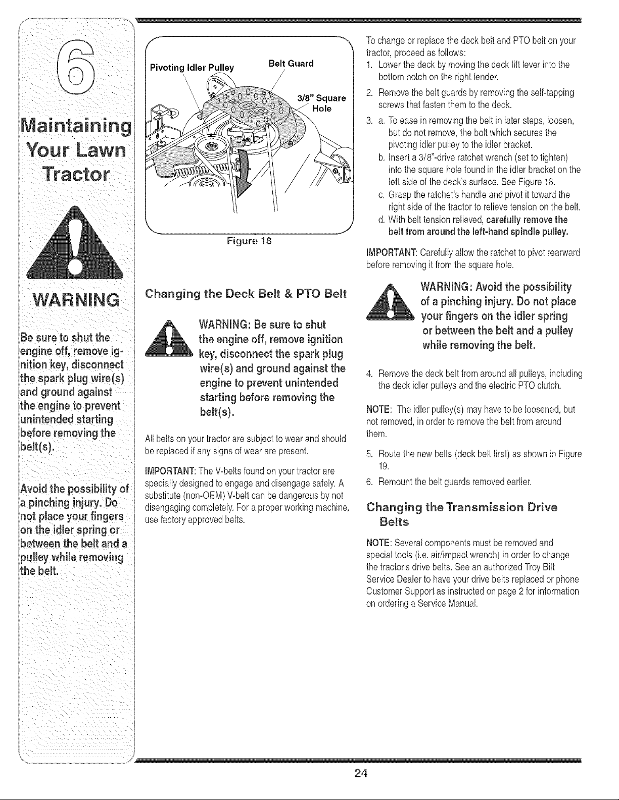
-- ", Tochangeor rep ace thedeck bet andPTObet onyour
tractor,proceedas follows:
I Pivoting Idler Pulley Belt Guard 1, Lowerthe deckby movingthedeck lift bver into the
\ / bottomnotchon the rightfender,
Your Lawn
Figure 18
"Square
Hole
2, Removethe beltguardsby removingthe seBtapping
screwsthatfastenthem to the deck,
3, a, To easein removingthe belt in latersteps, loosen,
but do not remove,the boltwhich securesthe
pivotingidlerpulby to the idlerbracket,
b, inserta 3/8"-driveratchetwrench(setto tighten)
intothe squarehob foundinthe idlerbracketon the
bft side of the deck'ssurface,SeeFigure18,
c, Graspthe ratchet'shandb and pivot it towardthe
rightside of the tractorto relbve tensionon the belt,
d, With belttension relbved,carefully removethe
belt from around the bft-hand spindle pulley.
IMPORTANT:Carefullyallowthe ratchetto pivotrearward
beforeremovingit fromthe squarehob,
WARNING
Be sure to shut the
engine off, remove ig=
nition key, disconnect
Lhespark pJugwire(s)
and ground against
the engine to prevent
unintended starting
before removing the
beJt(s).
Avoid the possibility of
a pinching injury. Do
not place your fingers
on the idler spring or
between the belt and a
pulley while removing
the belt.
Changing the Deck Be_t & PTO Be_t
WARNING: Be sure to shut
the engine off, remove ignition
key, disconnect the spark plug
wire(s} and ground against the
engine to prevent unintended
starting before removing the
belt(s).
Allbeltson yourtractorare subiectto wearandshould
bereplacedif anysigns of wearare present,
IMPORTANT:The V-beltsfoundon yourtractorare
speciallydesignedto engageanddisengagesafely,A
substitute(nomOEM)Wbeltcan bedangerousby not
disengagingcompletely,Fora properworkingmachine,
usefactoryapprovedbelts,
WARNING: Avoid the possibility
of a pinching injury. Do not place
your fingers on the idler spring
or between the belt and a pulley
while removing the belt.
4, Removethe deck belt fromaroundall pulbys, including
the deck idler pulleysandthe electricPTOclutch,
NOTE: The idler pulby(s) mayhaveto be loosened,but
not removed,in orderto removethe beltfrom around
them,
5, Routethe newbelts (deck beltfirst) as shownin Figure
19,
6, Remountthe beltguardsremovedearlbr,
Changing the Transmission Drive
Be_ta
NOTE:Severalcomponentsmust beremovedand
specialtools(i,e, air/impactwrench)inorderto change
the tractor'sdrivebelts, Seean authorizedTroyBilt
ServiceDeabr to haveyourdrivebelts replacedor phone
CustomerSupportas instructedonpage2 for information
onorderinga ServiceManual
/
24
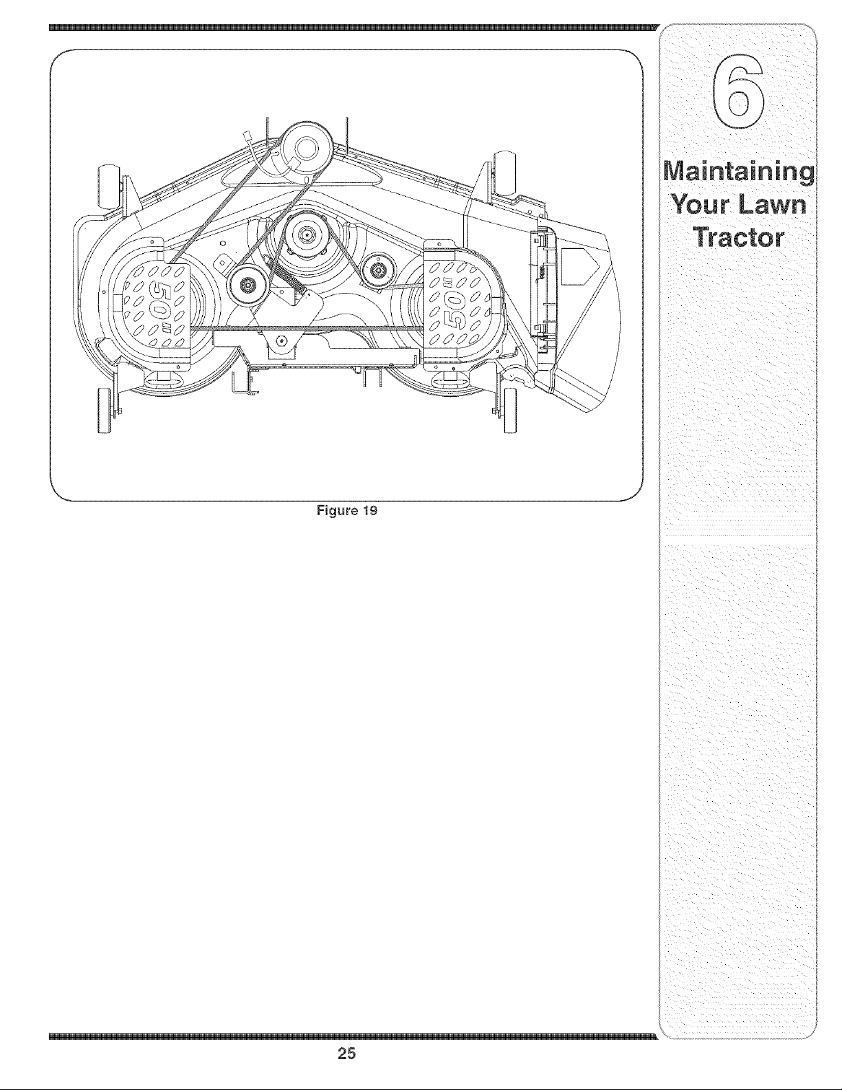
Figure 19
J
25

; of this manualbeforestoringfor an extendedperiod, Manualfor properenginecare priorto storingyourtractor,
WARNING
Drain fuel only into an
approved container
outdoors, away from
an open flame. Al-
low engine to coon.
Extinguish cigarettes,
cigars, pipes, and
other sources of igni=
tion prior to draining
fuel.
WARNING: Drain fueJ only into
an approved container outdoors,
away from an open flame. Allow
engine to coot. Extinguish
cigarettes, cigars, pipes, and
other sources of ignition prior to
draining fuel.
WARNING: Never store the
machine or fuel container indoors
where there is an open flame,
spark or pilot tight such as on
water heater, furnace, clothes
dryer or other gas appliance.
Attachments & Accessories
The followingattachmentsandaccessoriesare compatiblefor Model60TPHorseLawnTractors,Seethe retailer
fromwhichyou purchasedyour tractor,an authorizedTroy BiltService Dealeror phone 1-866-840-6483for informa-
tion regardingpriceandavailability,
NOTE:Model60TPLawnTractorsare NOTdesignedfor use withany typeof ground_engagingattachments(e,g,
filleror plow),Useofthis typeof equipmentWILLvoid thetractor'swarranty,
MODEL _ DESCRiPTiON
0EM-190-032
OEM-190-i92
OEM-190-193
OEM-190-218
OEM_190_607"
OEM-190-658
OEM_190_672
OEM-190-833
42-inchTwo-stageSnowThrower
50-inch BaggerKit
50-inch MulcherKit
BearWheelWeightKit
DeluxeTractorSunshade
GrilleGuard(mountsonfrontof tractor)
46-inch FrontDozerBlade
Notcompatiblewithtractorsequippedwitha GrassCollector
Never store the ma-
chine or fuel container
indoors where there is
an open flame, spark
or pilot light such
as on water heater,
furnace, clothes dryer
or other gas appliance.
26

iiiii_i_iii_ii_i_i_ii_iii_iW_i_!_!_!_i_ii_i_iiiii_iiiii_iH:!:!:!:!i_i_@iiiiiiii
_and instructions
27

For repairs beyond
the minor adjust-
ments listed here,
contact an authorized
service dealer.
Problem
Engine runs erratic
Cause
1, Unitrunningwith CHOKEapplied,
2, Sparkplugwire(s) loose,
3, Blockedfuel lineor stab fuel
4, Ventingas cap plugged,
5, Waterordirt infuel system,
6, Dirty aircbaner,
Remedy
1. PlacePTOknob (orlever)in
1, PushCHOKEcontrol(if so
equipped)in, or movethe throttle
controlout of the CHOKEposition,
2, Connectand tightenspark
plugwire(s),
3, Cban fuel line;fill tank with clean,
fresh(less than30 daysold)
gasoline,Replacefuel filter,if so
equipped,
4, Char ventor replaceif damaged,
5, Drainfuel tank, Refillwith
freshfuel
6, Replaceair cleanercartridge/eb=
mentor cleanpre=cleaner,if so
equipped,
28

Problem Cause Remedy
. 2, Air flowrestrbted,' 2, CLeangrassclippingsanddebris
, , aroundthe engine:scoe!!ng
• • finsandbbwer housing.
Enginehesitates at 1, Sparkplug(s)gaptooclose, 1, Removespark plug(s)and reset
high RPM thegap,
' ..... equipped, ........ .....
Excessive
Vibration
Uneven cut
1, Cuttingbladelooseor unbalanced,
2, Damagedor bentcutting blade,
1, Decknot balancedproperly,
2, Dullblade,
3, Uneventire pressure,
1, Tightenbladeandspindle,Balanc(
blade,
2, Replaceblade,
1, Performside-to-sidedeckadiust-
ment,
2, Sharpenor replaceblade,
3, Checktire pressureinall fourtires,
For repairs beyond
the minor adjust-
ments listed here,
contact an authorized
service dealer,
29
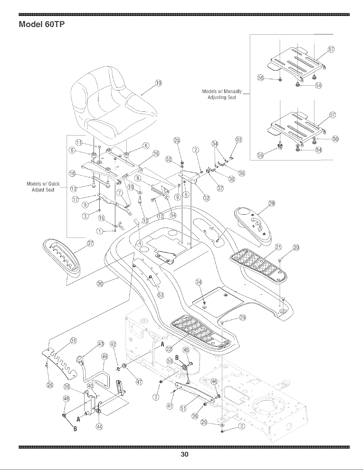
Model 60TP
Models w/Quick
Adjust Seat
Modelsw/Manually
Adjusting Seat
..... i
t_ ¸¸¸•'(iii_ii_ii_'i!¸ •
3O

Ref. Part No. Description
No.
1 710-1268t Screw,#10-16x.375
2 712-04063 Nut, FlangeLock,5/16-18,GrF
3 712-04064f Nut, FlangeLock, 1/4-20
4 720-0309At SeatAdiusterGrip
5 726-0201t Nut, Speed,.3125ID
6 731-04074f Spacer
7 732-0499t CompressionSpring.41x 1.5
8 732-1184 Spring,Extension,.84Dia.x 4.6
9 736-0275t Wash,Flat,.344x.688 x.065
10 736-3019t Wash,Flat,.531x1.062x.134
11 738-0137At Screw,Shld, .340x.285,1/4-20
12 738-0296 Screw,Shoulder,.437x.268
13 738-0966At Screw,Should,.50x.925,3/8-16
14 783_0209D SeatBracket,Lift
15 783_0611t SeatStop
16 783-0738Ct SeatPivotBracket
17 783-0739At SeatAdiustmentLever
18 783_0753t SeatAdiustmentSelector
19 757-04036 MediumBackSeat
20 726_3046 RatchetClip
21 735-0657 LR FootPad, Rubber
22 735-0656 RH FootPad,Rubber
23 710_0451 Bolt, Carriage,5/16_18.75,Grl
24 710-0599 Screw,1/4-20,0.500
25 710-0604A Screw,5/16-18,0.625
26 710-0895 Screw,1/4-15,0.750
27 731_1990 Cover,Lift Lever
28 731-2104C Cover,w/ CupHolder
29 736-3078 Washer,Flat,.344x 1.0x.063
Ref. Part No. Description
No.
30 783-04333A Fender
31 783-0677B Adiust.Brkt., Lift
32 783-1489B MountingBracket,Seat
33 710_0227 Screw,#8_18x.50
34 726_0279 Plate,Insulator
35 725-1303 SpringSwitch,Outer
36 725-1439 SpringSwitch,inner
37 726-0278 Plate,InsulatorBoss
38 683_04079 ShaftAssembly,Lift
39 712-04065 Nut,FlangeLock,3/8-16,GrF
40 714-0104 Pin,Cotter,.072Dia.x 1.13
41 714-0111 Pin,Cotter,3/32, 1.0
42 716-0106A Ring,EType,.625Dia.
43 720_0311 Grip, Handle,1/2
44 732_0874 Spring,Torsion
45 738-0138A Screw,5/16-18x.620Gr2
46 738-0380 Screw,Shld,.50x.27
47 741-0225 Bearing,RexFlange
48 746-0968 Cable,Lift, 16.16
49 747-04155 Handle,Lift
50 756_1154 Pulley,Roller
51 783_0678A Arm, Lift_LH& RH
52 736-0607 LockWasher,5/16
53 710-0726 Screw,5/16-12
54 738-04012At ShoulderScrew
55 720-04061t Knob,3/8-16
56 736-0300t FlatWasher,.406x .875x .059
57 783-04081At SeatPivotBracket,ManualAdi.
58 710-0870t HexHeadWasherScrew,3/8_16
t if Equipped
NOTE:Tractorfeaturesvaryby model NOTall partslistedaboveandpicturedon the previouspageare standard
equipment.
ustrated
parts,calltheCustomer
Service Line at
\
31
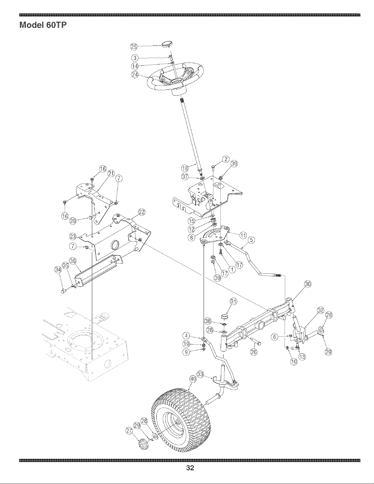
Model 80TP
32

Ref. Part No. Description
No.
1 710-04095 RexScrew,3/8-16, 1,00,Gr5
2 710-0514 RexScrew,3/8-16, 1,00,Gr5
3 710-0643 HexScrew,5/16-18,1,00,Gr5
4 711-1408 Link, Drag,RH
5 7114409A Link,Drag,LH
6 712-0214 Nut,Hex Lock,3/8-24
7 712-04065 Nut,FlangeLock,3/8-16,Grf
8 712-0459 Nut,Range Lock,7/16-20
9 712-3004A Nut,FlangeLock,5/16-18,Gr5
10 712-0240 Nut,Jam,7/16-20,Gr2
11 7174550E Gear,Steering,11/90Ratio
12 717-1554 Gear,Pinion,Steering
13 723-0448A BaliJoint,7/16-20,Lock
14 736-3004 Washer,Flat,,406 x,875x,105
15 736-3084 Washer,Flat,,51x 1,12x ,06
16 710q260A Screw,5/16-18,0,750
17 738-04154 Spacer,Shoulder,,38 x 1,00x ,31
18 738qOO1A Shaft,Steering,,6250Dx 24,25
19 741-0475 PlasticBushing,3801D
20 738-0143 Screw,Shoulder,,498x,340
21 783-0726E PivotBracket,SupportRH
22 783-0727D PivotBracket,SupportLH
23 783-0728 PivotBracket,Bar
24 631-04008 SteeringWheel
25 731-04681 SteeringWheeICap
26 738-04128 ShoulderScrew,,5 x 2,380,3/8-16
27 734-2290A DeluxeRubCap
28 736-0316 FlatWasher,,78x 1,589x ,06
29 714-04039 CotterPin, 5/32x 1,25
30 719-04105 Cast IronPivot Bar
31 731-04693 RubCap
32 638-04003 LHAxle Assembly,,750
33 638-04004 RHAxb Assembly,,750
34 711-0332 Pin,Clevis,,50 x,78
35 714-04023 CotterPin, Internal,,080x 1,5625
36 783-0720A AdiustmentBracket,Front
37 741-0656A RexFlangeBearing
38 726-04035 PushNut
39 712-0431 FlangeLockNut, 3/8-16
40 634-04087 WheelAssemblyComplete,15x 6
734-04040 Tire Only 15x 6 x 6
634-04081 RimOnly w/Valve Stem
parts, call the Customer
Service Line at
or visit
wwW:tioyb t,com:
\
33
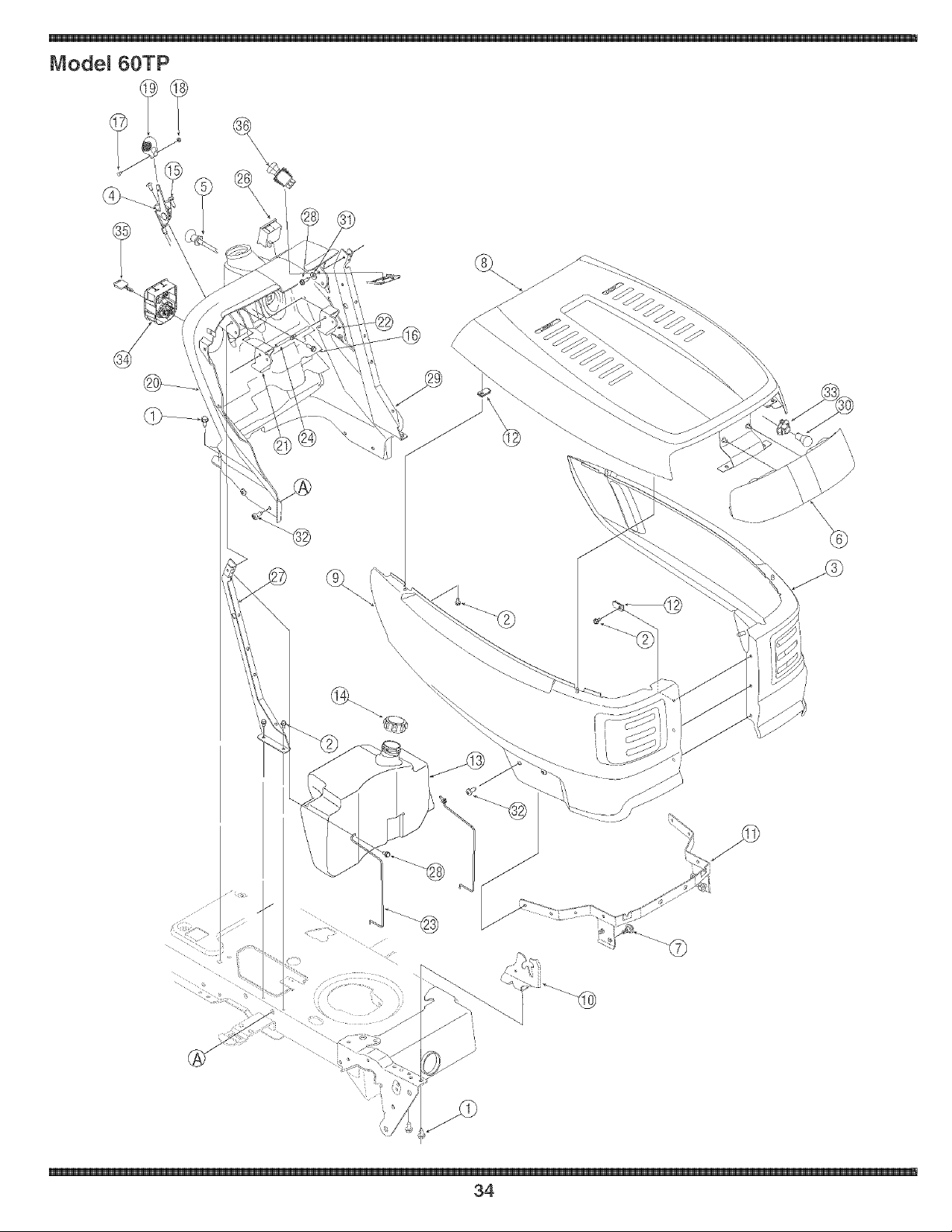
Model 60TP
\
\\\\
\
@
/
34

Part No. Description Ref. Part No. Description
Ref.
No.
1
2
3
4
5
6
7
8
9
10
11
12
13
14
15
16
17
18
19
710-0726
710-0599
783-04829
746-1100
746qO85A
731-05357
738-04091
783-04827
783-04828
783-04840
783-04841
783-04606A
712-0185
751q 0283
751-0603
710-1017
710-0895
710-3217
712-0142
731q857
Screw,5/16-12x.750
SelfqappingScrew,1/4-20x.5
SidePanel- LH
ThrottleControl
ChokeControl
HeadlightLens
ShoulderScrew.43x.29
Hood,T Style
SidePanel- RH
PivotBracket- RH
PivotBracket- LH
GrillPivotBracket
SpeedNut
FuelTank,ThreeGallon
FuelCap
Screw,1/4-14x.625
SelfqappingScrew,1/4-15x.75
TrussPhillipsScrew,#8-32x.375
HexNut,#8-32
ThrottleControlKnob
No.
20 731-05005B
21 731-04215
22 731-04217
23 747-04161
24 747-1196
25 629-04083t
26 725-04036B
27 783-04908
28 710-0642
29 783-04909
30 725-0963
31 736-0270
32 710q611B
33 725-1649
34 725-04227A
35 725-1745
725-1744
36 725-1752
-- 725-043361-
t NotShown
DashPanel
CruiseControlButton
ParkingBrakeButton
TankSupportRod
Brake/CruisePivotRod
HeadlightWire Harness
SystemsInd. Monitorw/Hr. Meter
RHDashSupportPlate
SelfqappingScrew,1/4-20x.75
LHDashSupportPlate
Lamp
BellWasher.265x.75x.062
Screw,5/16-18x.75
HeadlightSocket
ignitionSwitch
ignitionKeyw/plastic cover
ignitionKeyw/oplasticcover
ElectricPTOSwitch
Wire Harness
To order replacement
parts, call the Customer
Service Line at
1-800-648-6776,
or visit
\
35
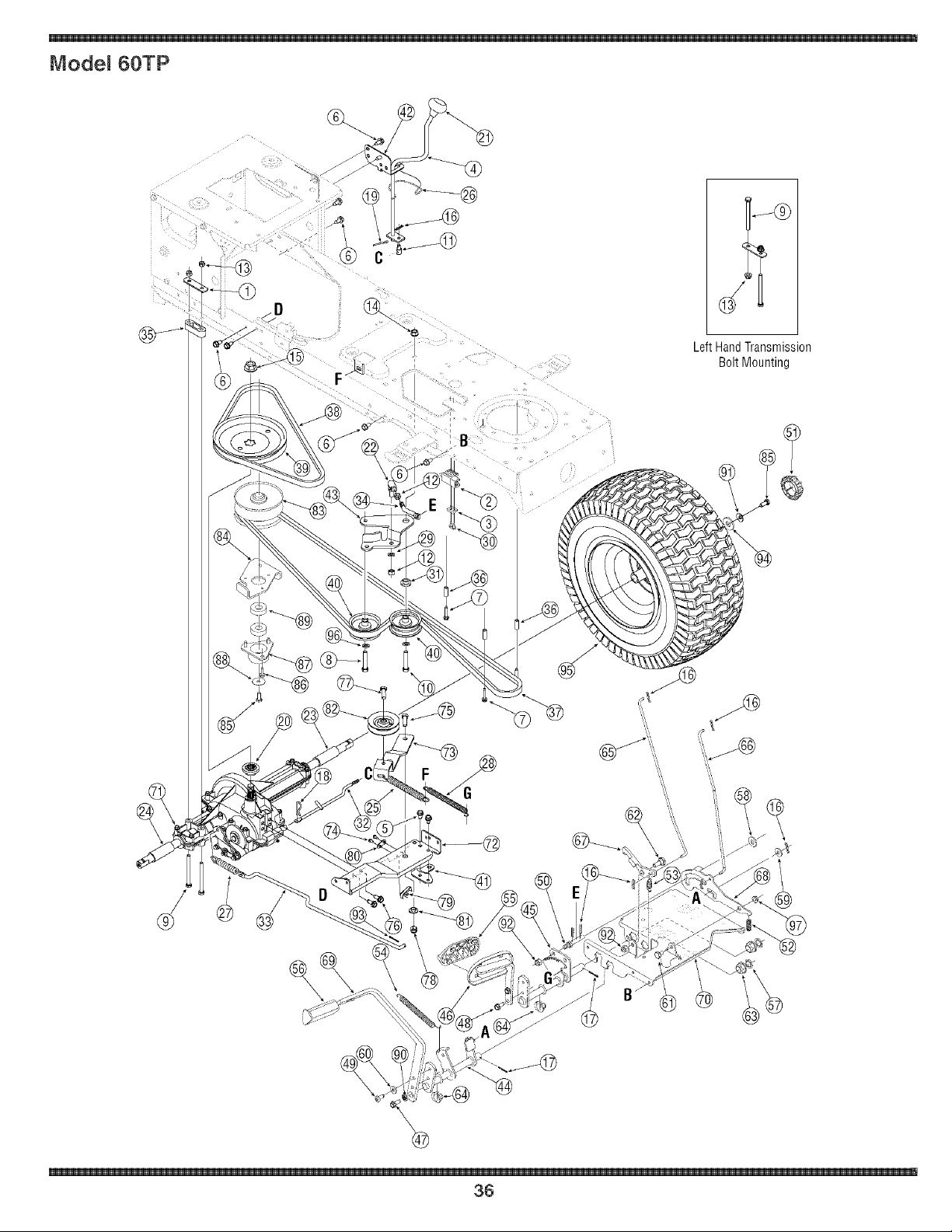
Model 60TP
Left Hand Transmission
Bolt Mounting
B
36

Ref. Part No. Description
No.
1 17840 MountingBracket,Transaxle
2 725-04039 Switch,Interlock
3 17962 Plate,Switch
4 647-04020 LeverAssembly,Shift
5 710-0607 Screw,5/16-18,0.500
6 710-0726 Screw,5/16-12,0.750
7 710-0809 Screw,1/4-20,1.250
8 710-1007 Screw,Seres,3/8-16, 1.500
9 710-1266 Screw,5/16-18,3.50, Gr5
10 710-3144 Screw,3/8-16,2.00,Gr5
11 711-0736 AdiustmentFerrule1/4-20x 1.
12 712-0241 Nut,Hex,3/8-24, Gr5
13 712-04063 Nut,FlangeLock,5/16-18,GrF
14 712-0431 Nut,FlangeLock,3/846, GrF
15 712-0700 Nut,Flange,9/16-18,Gr2
16 714-0104 Pin,Cotler.O72Dia.x 1.13
17 714-0111 Pin,Cotter,3/32, 1.0
18 714-0209 CotterPin,Internal,.125Dia.
19 714-0470 Pin,Cotter,1/8x 1.25
20 718-0758A PulleyHub,5/8 Spline
21 720-04028 Knob,Shift
22 723-3018 BallJoint
23 731-04602 Sleeve.758x.821x3.3125
24 731-04604 Sleeve.758x.821x 2.4375
25 732-0384 Spring,Extension,.62Diax 6.12
26 732-0525 SpringClip,Shifter
27 732-0716C Spring,Extension.59ODx 4.00
28 732-0963 Spring,Extension.50Diax 6.37
29 736-0169 Washer,Lock,3/8
30 710-0224 Screw,#10q6.50
31 738-0372B Spacer,Shoulder,1.00x.38 x.38
32 747-04146A Rod,Shift
33 747-04164 Rod, Brake
34 747-1127 IdlerRod,Adiustable,3/8
35 748-0334 Spacer.68
36 750-0566A Spacer.260x.372x 1.030
37 754-0467 Belt,V-Type
38 754-0468 Belt,V-Type
39 756-04002 Pulley,V-Type,7.25Dia.
40 756-04224 IdlerPulley,Flat2.75OD
41 783-04283 Bracket,Shift
Ref. Part No. Description
No.
42 783-04360 Bracket,Shift,F-N-R
43 783-04442 Idler Bracket,CenterDouble
44 647-0031B ControlAssembly,Brake
45 647-0032A ControlAssembly,Speed
46 683-0266 PedalAssembly
47 710-0650 Screw,5/16-18,0.875
48 710q260A Screw,5/16q8,0.750
49 710q611B Screw,5/16-18,0.750
50 711-04159B Pin,3/8-16x2.68
51 731-2290A Hub Cap
52 732-0335 Spring,Compression..405x1.17
53 732-0955 Spring,Extension.50OD x 1.41
54 732-0963 Spring,Extension.50OD x 6.37
55 735-0662 Pad
56 735-3049 Pad,Brake
57 736-0187 Washer,Flat.64 x 1.24x.06, Ht
58 736-0262 Washer,Flat.385x.870x.092
59 736-0300 Washer,Flat.406 x.875x.059
60 736-3008 Washer,Flat.344x.750x.120
61 738-0155 Screw,Shoulder.437Diax.162
62 738-0380 Screw,Shoulder,.50x.27Lg,
63 741-0225 Bearing,Hex Flange
84 741-3065B Split Bearing,Hex Flange
65 747-04093 Rod,BrakeLock
66 747-04096 Rod,CruiseControl
67 748-04039BI Latch,CruiseControl
68 783-0732A Bracket,Lockout
69 783-0773A Ped,Brake
70 783-04612 Bracket,SteeringSupport
71 618-04034 Transmission,SingleSpeed
72 683-04055A BracketAssembly,Torque
73 683-04130 Bracket,Idler
74 710-0227 Screw,#8-18x.50
75 710-0514 Screw,3/8-16, 1.00
76 710-0604A Screw,5/16q8.625
77 710-1315 Screw,3/8-16, 1.250
78 712-0130 Nut, Lock,3/8-16,Nylon
79 725-1644 SwitchSpring,Short
80 726-0320 Plate,Insulator
81 750-04294 Spacer,Shoulder
82 756-04209 Pulley,V-Type,3.06
Continued on next page
Parts List
To order replacement
parts, call the Customer
Service Line at
1-800-648-6776,
orvisit
www.troybilt.com.
\
37

Model 60TP
To order replacement
parts, call the Customer
Service Line at
1=800=648=6776,
or visit
www.troy bilt.com.
Ref. I Part No. Description
No.
I
83 656=04015 PulleyAss'y,VariableSpeed
84 683=04129 Bracket,Pulley
85 710=0627 Screw,5/16=24,.750
86 710=1652 Screw,1/4=20,.625
87 718=04012 Cup,Bearing
88 736=0362 Washer,Flat
89 741=0600 BallBearing
90 736=0119 LockWasher,5/16
91 736=0242 Washer,Bell.340x.872x.060
92 712=04065 Nut,FlangeLock,3/8=16,GrF
93 714=0507 Pin,Cotter,3/32x.750
94 736=0430 FlatWasher.350x 1.59x.062
95 634=0177 WheelAssyComp,20x 10x 8
734=1873 Tire Only20 x lOx 8
634=0222 RimOnly w/Valve Stem
96 736=3010 FlatWasher,.407x .812x .135
97 712=3004A Nut,FlangeLock,5/16=18,Gr 5
38
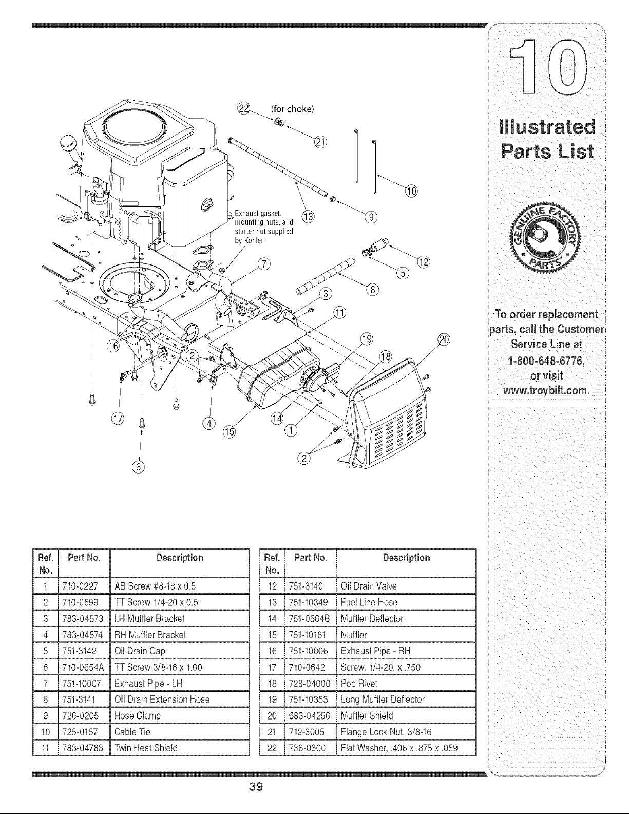
_i_ill _i i_i_I _ iiii_i
Exhaustgasket,
mounting nuts, and
starter nut supplied
Kohler
Ref. Part No.
No.
1 710-0227
2 710-0599
3 783-04573
4 783-04574
5 751-3142
6 710-0654A
7 751-10007
8 751-3141
9 726-0205
10 725-0157
11 783-04783
Description
ABScrew#8-18x 0,5
TT Screw1/4-20x 0,5
LH MufflerBracket
RHMufflerBracket
Oil DrainCap
TT Screw3/8-16x 1,00
ExhaustPipe- LH
Oil DrainExtensionHose
HoseClamp
CaNeTie
TwinHeatShield
Ref.
No.
12 751-3140
13 751-10349
14 751-0564B
15 751-10161
16 751-10006
17 710-0642
18 728-04000
19 751-10353
20 683-04256
21 712-3005
22 736-0300
Part No. Description
Oil DrainValve
FuelLineHose
MufflerDeflector
Muffler
ExhaustPipe- RH
Screw,1/4-20,x ,750
PopRivet
LongMufflerDeflector
MufflerShMd
FlangeLockNut,3/8-16
FlatWasher,,406x ,875x ,059
39
To order replacement
parts, ealJ the Customer
Service Line at
1=800=648=6776,
or visit
www.troybilt.com.
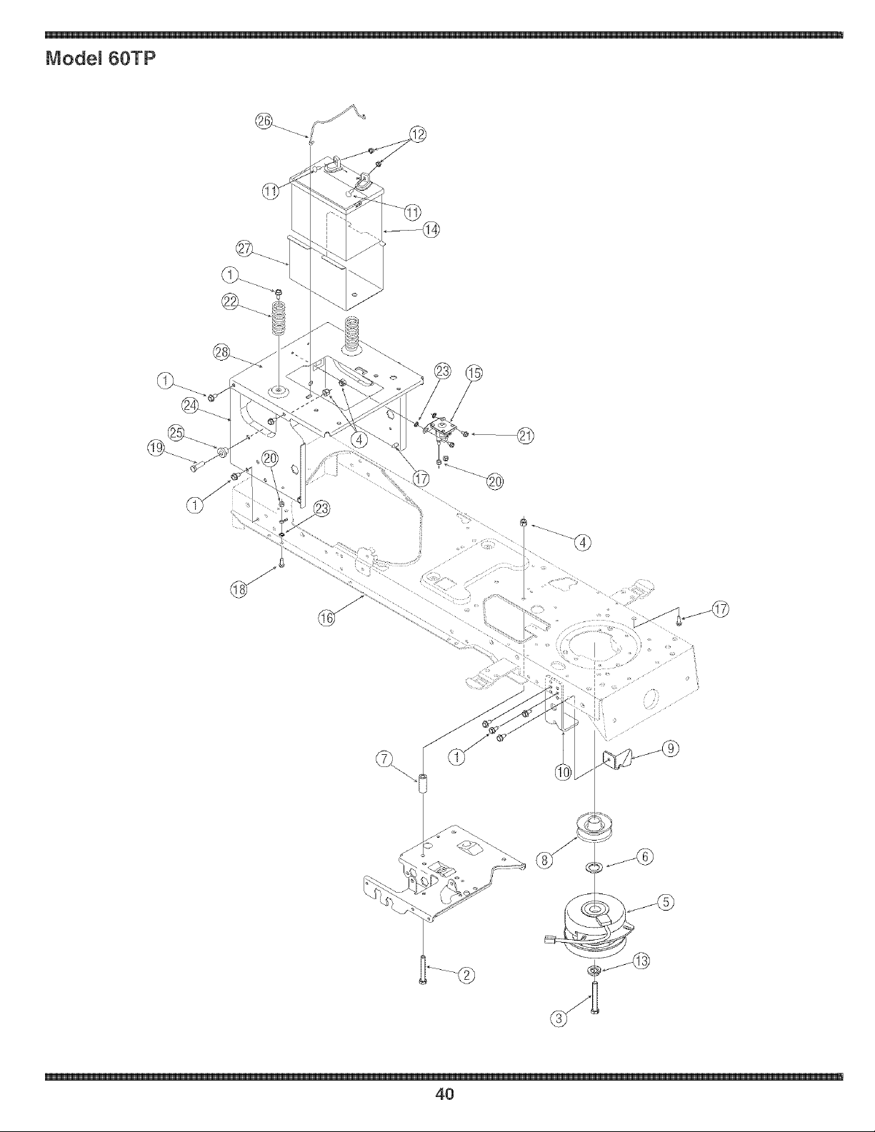
Model 60TP
\I
40

Ref. Part No. Description
No.
1 710-0728 Screw,5/18-12,0.75
2 710-0859 Screw,3/8-16, 2.50,Gr5
3 710-04379A Screw,7/16-20,3.50,Gr5, Lock
4 712-04065 Nut,Range Lock,3/8-16,GrF
5 717-04174 PTOClutch,Electric
6 736-0277 Washer,Flat, 1.031x 1.620x.095
7 748-0415B Spacer.385IDx.635ODx 1.54
8 756-0639A Pulley,Engine,3.56Diameter
9 783-04419B ClutchBracket
10 783-04467 DeckBracket,Up-Stop
11 710-0703 Screw,Carriage,1/4-20.75,Gr5
12 712-0271 Nut,Seres,1/4-20
13 736-0171 LockWasher,7/16
14 725-1750A Battery,235 CCA
15 725-1428A Solenoid,12V,100Amp
16 683-04173 FrameAssembly,Lower
17 710-0607 Screw,5/16-18,0.500
18 710-0842 Screw,1/4-20,0.750
19 710-3005 Screw,3/8-16, 1.25,Gr5
20 712-04064 Nut,Range Lock,1/4-20,GrF
21 710-0599 Screw,1/4-20,0.50
22 732-04035 Spring,Compr. 1.28OD x 3.125
23 736-0222 Washer,Lock,1/4, External
24 783-04809 Frame,Upper
25 738-04058 Spacer,Shoulder.38x 1.0x.70
26 747-04121A HoldRod,Battery
27 783-0349 BatteryTray
28 783-0432% SeatBracket,Frame
\
41
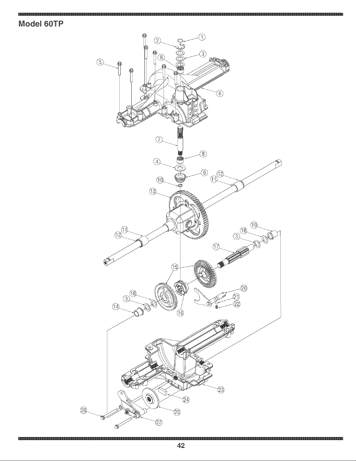
Model 60TP
42

Ref. Part No. Description
No.
1 732-0614 Ring,Wire
2 716-0231 Ring,E Type.750
3 736-0336* FlatWasher,5/8x 1.0x.030
736-0337* FlatWasher,5/8 x 1.0x.040
736-0349* FlatWasher,5/8 x 1.0x.020
4 736-0335 Washer,Thrust.635x 1.26x.06
5 710q325 SelfqappingScrew,1/4-20x 1.625
6 719-04017 UpperRousing
7 711q109 input Shaft
8 741-0335 NeedleBearing.625x.813x.495
9 717-1464 144oothBevelPinion
10 716-0108 RetainingRing.437
11 741-0340 SleeveBearing,.75x.1.0x1.0
12 721-0338 Seal.75x 1.0x.125
13 618-04041 DifferentialAssembly
14 741-0336 FlangeBearing,5/8 x 3/4 x 3/4
15 717-04056 424oothBeveIGear
16 718-04045 ClutchCollar
17 711-04134 DriveShaft
18 736-0495* ThrustWasher,1.0x.632x.O
736-0494* FlatWasher.632x 1.00x.035
19 741-0337 FlangeBearing,5/8 x 3/4 x 15/16
20 611-0011 DetentShaftAssembly
21 741-0862 DetentBall
22 732-0863 CompressionSpring
23 719-04018 LowerHousing
24 717-0678 BrakePuck
25 761-0202 BrakeDisc
26 710q206 Self4appingScrew,1/4-20x 2.375
27 661-0001 BrakeAssembly
-- 737-0148 Grease(19oz.)
* Useapplicableflat washer(ref.#'s 3 or 18) in this applicationallowing.0150/.0020in. end-play
NOTE: If rebuildingthe upperhousing,includetwoounces(2oz.)of Unirex®N3grease(Part No.737-0289)in the
input shaftcavity.
List
To order replacement
parts, call the Customer
Service Line at
1-800-648-6776,
or visit
www.troybilt.com.
\
43
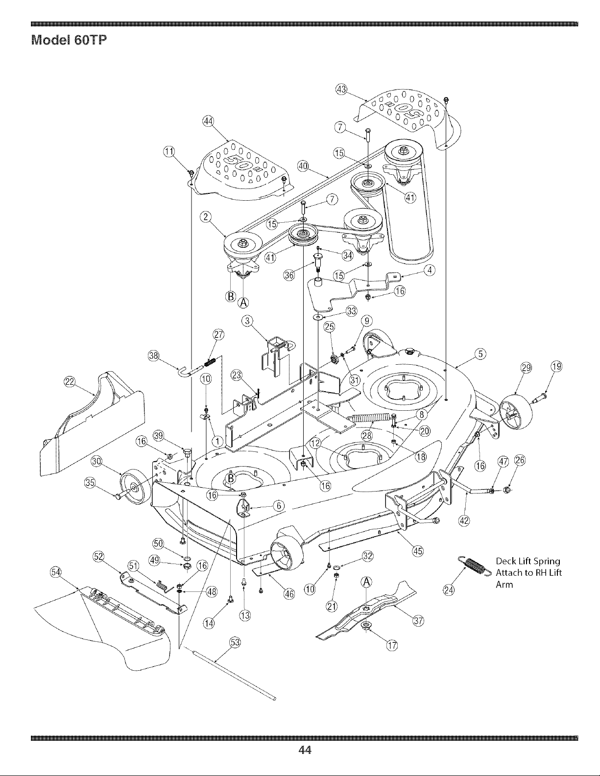
Model 60TP
J
Deck Lift Spring
Attach to RH Lift
(_ Arm
44

Ref. Part No. Description
No.
1 16606 Hook,Retainer
2 618=04125 SpindleAssembly
3 683=0254B HangerBracketAssembly
4 683=04098 Idler Bracket
5 683=04075 Weldment,50=inchDeck
6 703=3279 Chute Stop
7 710=0347 Screw,3/8=16,1.75
8 710=3103 Screw,5/16=18x 2.00
9 710=0528 Screw,5/16-18,1.25,Gr5
10 710=0599 Screw,1/4=20x 0.5
11 710=0607 Screw,5/16=18x.500
12 710=1260A Screw,5/16-18x.75
13 710=04095 Screw,3/8=16x 1.0
14 710=3178 Screw,Carriage,3/8=16x.75
15 738=0300 Washer,Flat,.408x.875x.059
16 712=04065 Nut, NylonLock,3/8=16
17 712=0417A Nut, Hex,Flange,5/8-18
18 712=04063 Nut, NylonLock,5/16=18
19 738=3056 Shld.Screw,1/2x 2.50Lg.
20 712=3010 Nut, Hex,5/16=18,Gr5
21 712=3019 Nut,7/16-14
22 731=04651t MulchPlug
23 714=0470 Pin,Cotter, 1/8x 1.25
24 732=0934 Exten.Spring,1.15Die. x 5.99Lg.
25 717=04074 DeckAdiustmentGear
26 712=3083 Lock Nut, Hex,1/2=13,Nylon
27 732=0306A Spring,Compression.531x 1.75
28 732=0459B Spring,Extension.94x6.74
Ref. Part No. Description
No.
29 734=04155 DeckWheel, 5.0
30 734=0973 DeckWheel,5.0
31 738=0119 Washer,Lock,5/16, RegularDuty
32 738=0407 Washer,Bell.45 x 1.0x.062
33 736=0406 Washer,Flat.442 x 1.38x.060
34 737=3000 Fitting,Lube,3/16
35 738=0373 ShoulderScrew
36 738=3005A Screw,Shoulder,.68x1.59
37 742=04053A Blade
38 747=1116 Rod,DeckRelease.375Dia
39 738=04146 ScrewPlug,M16x 1.5
40 754=04077 Belt,V=Type,Aramid
41 756=04129 Pulley,Idler,3.5"
42 747=1324 Rod,DeckAdiustment
43 783=04399 LHBeltCover
44 783=04400 RHBeltCover
45 783=04414 DeckSkirt,Center
46 783=04415 DeckSkirt,RH
47 712=0206 HexNut,1/2=13
48 712=0229 PushNut,3/8
49 712=0641 HexNut,M16=1.5
50 738=0225 LockWasher,5/8
51 732=3070 TorsionSpring.441Dx 2.10
52 783=04470 Chute Bracket
53 711=1762 HingePin
54 731=3131A ChuteDeflector
631=04070 ChuteAss'y(IncludeRef.#51=54)
t If Equipped
,,rderrepmoCement
parts, call the Customer
_ Service Line at
!=800=648,6776'
www.troybiit.eom. /
For a proper working machine
use Factory Approved Parts.
V°belts are designed to
engageand disengage safely.
A substitute (non OEM) V=belt
can be dangerous by not
\
45

Use this page to make
notesandwritedown
importantinformation.
46

CAUFORNJA EMiSSiON CONTROL WARRANTY STATEMENT
YOUR WARRANTY RIGHTS AND OBLIGATIONS
The CaliforniaAir ResourcesBoardand MTDConsumerGroupInc are pleasedto explainthe evaporativeemissioncontrolsystemwarrantyon your2006 lawn
mower.In California,new lawnmowermust be designed,built andequippedto meet the State'sstringentanti-smogstandards.MTD ConsumerGroupInc must
warrantthe EECSon your lawnmowerfor the periodof time listedbelow providedthere has beenno abuse,neglector impropermaintenanceof your lawnmower.
YourEECSmayincludeparts such as thecarburetor,fuel-injectionsystem,the ignitionsystem,catalyticconverter,fuel tanks,fuel lines,fuelcaps, valves,
canisters,filters,vaporhoses,clamps,connectors,and otherassociatedemission-relatedcomponents.
Where a warrantaMe condition exists, MTDConsumer Group _newill repair your Hawnmower at no cost to you ineHudingdiagnosis, parts and Habor.
MANUFACTURER'S WARRANTY COVERAGE:
Thisevaporativeemissioncontrol systemis warrantedfor twoyears. If anyevaporativeemission-relatedpart onyour equipmentis defective,the partwill be
repairedor replacedby MTDConsumerGroup Inc.
OWNER'S WARRANTY RESPONSIBILITIES:
Asthe lawn mowerowner,you are responsiblefor performanceof the requiredmaintenancelistedin yourowner'smanual. MTDConsumerGroup Inc recom-
mendsthat you retain all receiptscoveringmaintenanceon your lawnmower,but MTDConsumerGroup Inccannot denywarrantysolelyfor the lackof receipts.
Asthe lawn mowerowner,you shouldhoweverbe awarethat MTDConsumerGroupInc maydenyyou warrantycoverageif yourlawn moweror a part has failed
dueto abuse,neglect, or impropermaintenanceor unapprovedmodifications.
Youare responsiblefor presentingyourlawn mowerto MTDConsumerGroupInc'sdistributioncenteror servicecenteras soonas the problemexists.The
warrantyrepairsshouldbecompletedin a reasonableamountof time, notto exceed30 days.If you havea questionregardingyour warrantycoverage,you should
contactthe MTDConsumerGroupIncService Departmentat 1-800-800-7310.
GENERAL EMISSIONS WARRANTY COVERAGE:
MTDConsumerGrouphc warrantsto the ultimatepurchaserandeachsubsequentpurchaserthat the lawnmower is: Designed,built and equippedso as to
conformwithall applicableregulations;and freefrom defectsin materialsand workmanshipthatcausethe failure of a warrantedpart to be identicalin all material
respectsto that part as describedin MTDConsumerGroupInc's applicationfor certification.
Thewarranty periodbeginson the datethe lawnmoweris deliveredto an ultimatepurchaserorfirst placedinto service.Thewarranty periodis twoyears.
Subjectto certain conditionsand exclusionsas statedbelow,the warrantyon emission-relatedparts is as follows:
1. Anywarrantedpart that is not scheduledfor replacementas requiredmaintenanceinthe writteninstructionssupplied, is warrantedfor thewarranty period
statedabove. If the part fails duringthe periodof warrantycoverage,the partwill be repairedor replacedby MTDConsumerGroupInc accordingto subsection
(4) below. Anysuch part repairedor replacedunderwarrantywill be warrantedfor the remainderof the period.
2. Anywarrantedpart that is scheduledonly for regularinspectioninthe writteninstructionssuppliedis warrantedfor thewarranty periodstated above.Any such
part repairedor replacedunderwarrantywill be warrantedfor the remainingwarrantyperiod.
3. Any warrantedpart that is scheduledfor replacementas requiredmaintenanceinthe written instructionssuppliedis warrantedfor the periodof time beforethe
first scheduledreplacementdatefor that part. If the part failsbeforethe firstscheduledreplacement,the partwill be repairedor replacedby MTDConsumer
GroupInc accordingto subsection(4) below. Anysuch part repairedor replacedunderwarrantywillbe warrantedfor the remainderof the periodpriorto the
first scheduledreplacementpointfor the part.
4. Repairor replacementof any warrantedpart underthe warrantyprovisionshereinmustbe performedat a warrantystationat no chargeto the owner.
5. Notwithstandingthe provisionsherein,warrantyservicesor repairswill beprovidedat all of our distributioncentersthat arefranchisedto servicethe subject
enginesor equipment.
6. The lawnmowerowner will not bechargedfor diagnosticlaborthat is directlyassociatedwithdiagnosisof a defective,emission-relatedwarrantedpart,
providedthat such diagnosticwork is performedat a warrantystation.
7. MTDConsumerGroupInc is liablefor damagesto other engineor equipmentcomponentsproximatelycaused bya failure underwarrantyof any warranted
part.
8. Throughoutthe lawnmowerwarrantyperiodstated above,MTDConsumerGroupIncwill maintaina supplyof warrantedparts sufficientto meetthe expected
demandfor suchparts.
9. Any replacementpart may be usedinthe performanceof any warrantymaintenanceor repairsand mustbe providedwithoutchargeto the owner.Suchuse will
not reducethe warrantyobligationsof MTDConsumerGroupInc.
10.Add-onor modified partsthat are notexemptedbythe Air ResourcesBoardmaynot beused.The use of any non-exemptedadd-onor modifiedparts by the
ultimatepurchaserwillbe groundsfor disallowinga warrantyclaims. MTDConsumerGroup Incwill not be liableto warrantfailures of warrantedparts caused
bythe use of a non-exemptedadd-onor modifiedpart.
WARRANTED PARTS:
The repairor replacementof any warrantedpartotherwiseeligiblefor warrantycoveragemay be excludedfrom such warrantycoverageif MTDConsumerGroup
Inc demonstratesthat thelawn mowerhas been abused,neglected,or improperlymaintained,andthat such abuse, neglect,or impropermaintenancewasthe
directcauseof the need for repairor replacementof the part.That notwithstanding,any adjustmentof a componentthat hasa factory installed,and properly
operating,adjustmentlimiting device is still eligiblefor warrantycoverage.The following emissionwarrantyparts list are covered:FuelLine,Fuel Line Clamps
m

MANUFACTURER'S LIMITED WARRANTY FOR
®
The limitedwarrantyset forthbelowis givenbyTroy_BiltLLCwithrespect
to newmerchandisepurchasedand usedin the UnitedStates,its posses_
sionsandterritories.
"Troy_Bilt"warrantsthis productagainstdefects in materialand workmam
shipfor a periodof two (2) years commencingon thedate of original
purchaseandwill,at its option,repairor replace,freeof charge,any part
foundto be defectivein materialsor workmanship.This limitedwarranty
shallonly applyif this producthasbeen operatedand maintainedin
accordancewiththe Operator'sManualfurnishedwiththe product,and
has notbeen subiectto misuse,abuse,commercialuse,neglect,accident,
impropermaintenance,alteration,vandalism,theft,fire,water,or damage
becauseof other perilor naturaldisaster.Damageresultingfromthe
installationor use ofany part, accessoryor attachmentnot approvedby
Troy_Biltfor use with theproduct(s)coveredby this manualwill voidyour
warrantyas to any resultingdamage.
Normalwearpartsarewarrantedto befree fromdefects in materialand
workmanshipfor aperiodof thirty (30)daysfromthedate of purchase.
Normalwearpartsinclude,butare notlimitedto itemssuch as: batteries,
belts,blades,bladeadapters,grass bags,rider deck wheels,seats,snow
throwerskidshoes,shaveplates,augerspiralrubberandtires.
NOWTO OBTAIN SERVICE: Warranty service is available, WITH
PROOFOF PURCHASE,through your local authorizedservice
dealer. To locate the dealer in your area, check your Yellow Pages,
or contact Troy-Bilt LLC at RO. Box 361131,Cleveland, Ohio 44136-
0019, or can 1-866-840-6483 or 1-330-558-7220,or log on to our
Web site at www.troybilt.com.
This limitedwarrantydoesnot providecoverageinthe followingcases:
a. The engineor componentparts thereof.These itemsmay
carrya separatemanufacturer'swarranty.Referto applicable
manufacturer'swarrantyfor termsand conditions.
b. Logsplitterpumps,valves,and cylindershavea separateone
yearwarranty.
c. Routinemaintenanceitemssuchas lubricants,filters,blade
sharpening,tune_ups,brakeadiustments,clutch adiustments,
deckadiustments,andnormaldeteriorationof the exteriorfinish
dueto use or exposure.
d. Servicecompletedbysomeoneotherthanan authorizedservice
dealer.
e. Troy_Biltdoesnot extendanywarrantyfor productssold or
exportedoutsideof the UnitedStates,its possessionsand
territories,exceptthosesold throughTroy_Bilt'sauthorized
channelsof exportdistribution.
f. Replacementpartsthatare notgenuineTroy_Biltparts.
g. Transportationchargesandservicecalls.
No impliedwarranty, includingany impliedwarranty of merchant°
ability of fitness for a particular purpose, applies after the applicable
period of express written warranty above as to the parts as identi-
fied. No other express warranty, whether written or oral, except as
mentioned above,given by any person or entity, includinga dealer or
retailer,with respect to any product, shall bind Troy-Bilt. During the
period of the warranty,the exclusive remedy is repair or replacement
of the product as set forth above.
The provisions as set forth inthis warranty providethe sole and
exclusive remedy arising from the sale. Troy-Bilt shall not be liable
for incidental or consequential loss or damage including, without
limitation, expenses incurred for substitute or replacement lawn care
services or for rental expenses to temporarily replace a warranted
product.
Somestatesdo not allowtheexclusionor limitationof incidentalor
consequentialdamages,or limitationson howlongan impliedwarranty
lasts,so the aboveexclusionsor limitationsmaynotapplyto you.
In no eventshall recoveryof any kind be greaterthanthe amountof the
purchasepriceof the productsold. Alteration of safety features of the
product shall void this warranty. Youassumethe risk and liability for
loss,damage,or injuryto youand yourpropertyand/or to others and their
propertyarisingout of the misuseor inabilityto use the product.
This limitedwarrantyshall notextendto anyoneotherthanthe original
purchaseror to the personfor whomit waspurchasedas a gift.
HOWSTATELAW RELATESTO THiSWARRANTY:This limitedwar-
rantygh,'esyouspecificlegalrights,andyou mayalso haveother rights
whichvaryfromstateto state.
IMPORTANT:OwnermustpresentOriginalProofof Purchaseto obtain
warrantycoverage.
TROYBILT LLC, P.O. BOX 361131 CLEVELAM D, OHIO 44136-0019; Phone: 1(866} 840-6483, 1-330-558-7220