Loading ...
Loading ...
Loading ...
1-6
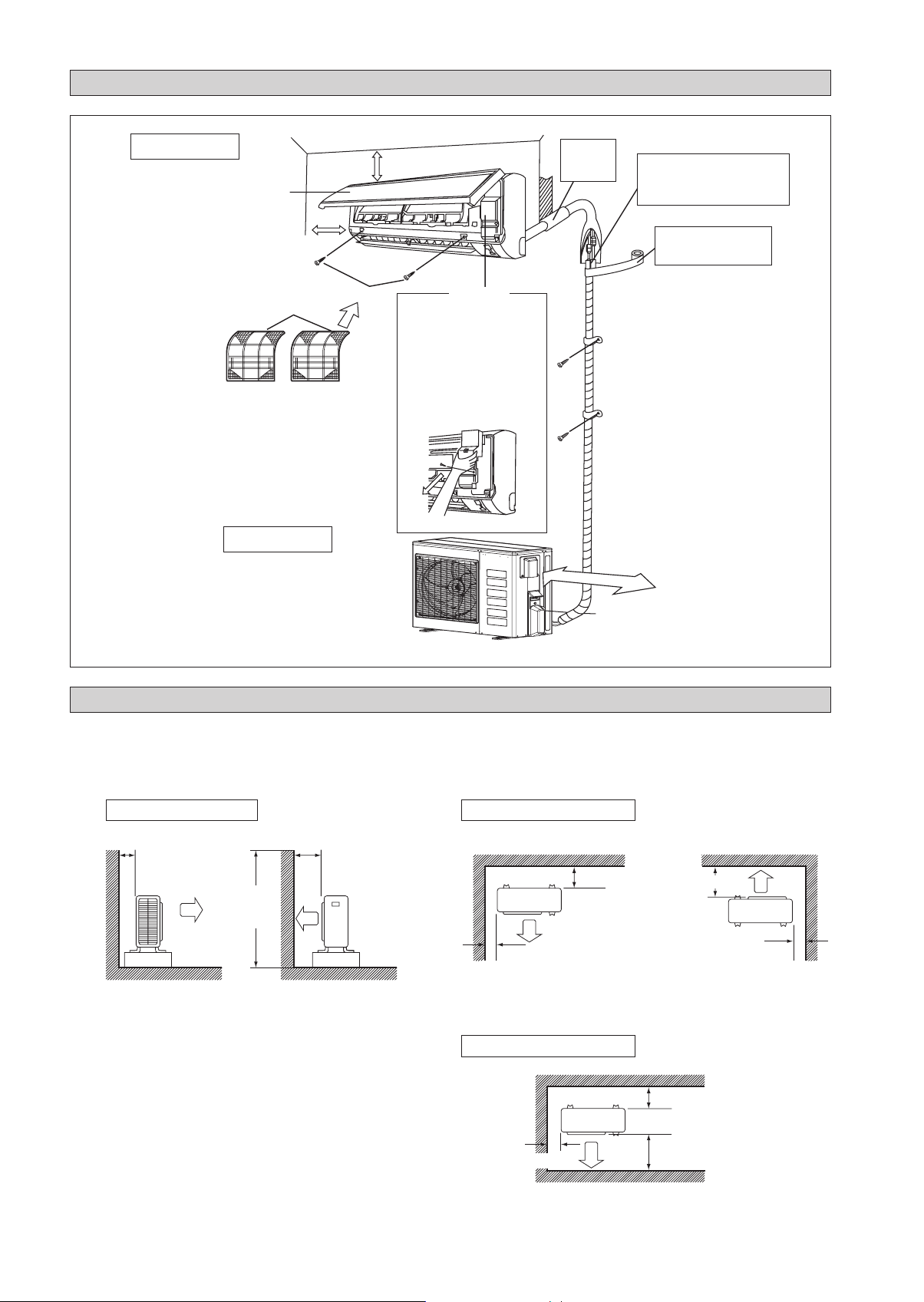
INSTALLATION DIAGRAM
Indoor Unit
Air filter
M4 x 12L
Front panel
2-3/16" (55mm) or more from ceiling
Outdoor Unit
1-15/16" (50mm) or more
from walls (on both sides)
Caulk pipe
hole gap
with putty.
Cut thermal insulation pipe to an
appropriate length and wrap it with
tape, making sure that no gap is left
in the insulation pipe’s cut line.
Wrap the insulation pipe
with the finishing tape
from bottom to top.
Service lid
19-11/16" (500mm) from wall
n Opening service lid
Service lid is removeable.
n Opening method
1) Remove the service lid
screws.
2) Pull out the service lid
diagonally down in the
direction of the arrow.
3) Pull down.
INSTALLATION OF THE OUTDOOR UNIT (09/12)
Where a wall or other obstacle is in the path of outdoor unit’s intake or exhaust airflow, follow the installation guidelines
below.
For any of the below installation patterns, the wall height on the exhaust side should be 47-1/4" (1200mm) or less.
•
•
Wall facing two sides
More than 1-15/16 (50)
Wall facing one side
More than 3-15/16 (100)
More than 1-15/16 (50) More than 1-15/16 (50)
Top View
Side View
More than
3-15/16 (100)
More than
5-7/8 (150)
More than 5-15/16 (150)
More than 11-13/16 (300)
More than 1-15/16 (50)
Unit : Inch (mm)
47-1/4
(1200)
or less
Wall facing three sides
Top View
Loading ...
Loading ...
Loading ...