Loading ...
Loading ...
Loading ...
6, Connectthepowersupplygroundwiretothegreenground
connectorandtightensecurely.
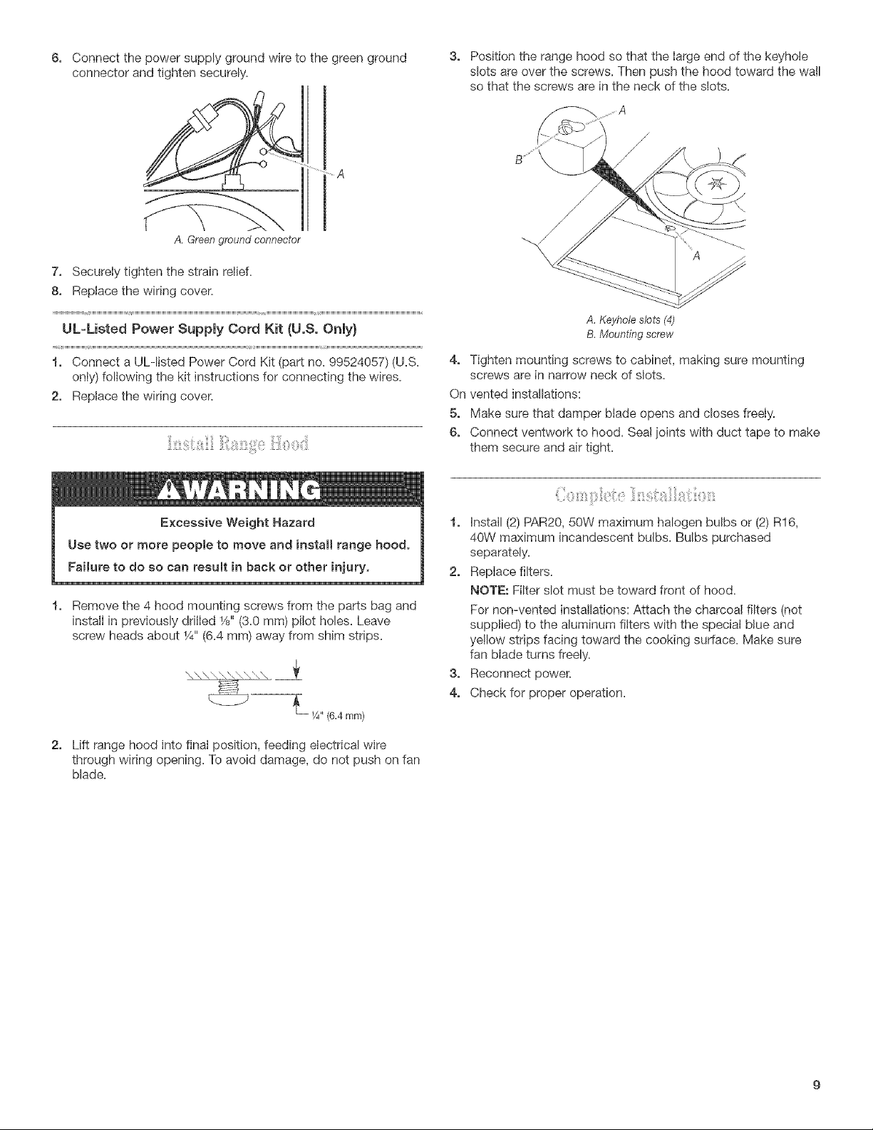
3, Positiontherangehoodsothatthelargeendofthekeyhole
slotsareoverthescrews.Thenpushthehoodtowardthewall
sothatthescrewsareintheneckoftheslots.
.... A
A. Green ground connector
7, Securely tighten the strain relief.
8, Replace the wiring cover.
UL-Listed Power Supply Cord Kit {U.S. Only}
1, Connect a ULqisted Power Cord Kit (part no=99524057) (U.S=
only) following the kit instructions for connecting the wires.
2, Replace the wiring cover.
A, Keyhole slots (4)
B. Mounting screw
4, Tighten mounting screws to cabinet, making sure mounting
screws are in narrow neck of slots.
On vented installations:
5, Make sure that damper blade opens and closes freely.
6, Connect ventwork to hood. Sea! joints with duct tape to make
them secure and air tight.
Remove the 4 hood mounting screws from the parts bag and
install in previously drilled 1/8"(3.0 mm) pilot holes. Leave
screw heads about 1/4"(6.4 mm) away from shim strips.
1, Install (2) PAR20, 50W maximum halogen bulbs or (2) R16,
40W maximum incandescent bulbs. Bulbs purchased
separately.
2, Replace filters.
NOTE: Filter slot must be toward front of hood.
For non-vented installations: Attach the charcoal filters (not
supplied) to the aluminum filters with the special blue and
yellow strips facing toward the cooking surface. Make sure
fan blade turns freely.
3, Reconnect power.
4, Check for proper operation.
2, Lift range hood into final position, feeding electrical wire
through wiring opening. To avoid damage, do not push on fan
blade.
Loading ...
Loading ...
Loading ...