
Snowblade
ts125
AE-015-001GI
Julius Tielbürger GmbH & Co. KG Maschinenfabrik
Postdamm 12 D-32351 Stemwede-Oppenwehe Tel.: +49 (0) 57 73/80 20 Fax: +49 (0) 57 73/81 75
Internet: www.tielbuerger.de
Operating instructions
and
assembly instructions
Copyright © 2016 by Julius Tielbürger GmbH & Co. KG, Stemwede Reproduction not permitted, neither in part nor in full. KR-392-002GI REV. 00
EN- Translation of the Original Operating Instructions
171506095/0EN

This document is a publication by Julius Tielbürger GmbH & Co KG, Postdamm 12, D-32351 Stemwede-Oppenwehe (www.
tielbuerger.de).
This document represents the technical status at the time of printing. Changes in technology and equipment reserved. Shown
Illustrations and images may differ from the original.
All rights including translation reserved. Reproduction by any method, e.g. photocopy, microlming or the capture in electro-
nic data processing systems, require the prior written approval by the editor. Reprinting, also in part, is prohibited.
All trademarks, registered trademarks, trade names and brand names are the property of their respective owners and are recog-
nized by us.
© Copyright 2016 by Julius Tielbürger GmbH & Co KG

3
Content
1 Operating and assembly instructions ........................................................................................................................... 4
1.1 General ..................................................................................................................................................................... 4
1.2 Warnings and symbols .............................................................................................................................................. 5
2 Fundamental safety instructions .................................................................................................................................. 6
2.1 Designated use of the machine ................................................................................................................................. 6
2.2 Organizational measures .......................................................................................................................................... 6
2.3 Selection and qualication of personnel - Basic responsibilities ............................................................................. 7
3 Condition at delivery and scope of delivery ................................................................................................................ 8
4 Illustration of device showing danger area, description of components, position of safety stickers and identication
plate ..................................................................................................................................................................................... 9
5 Components of the Tielbürger quick-release system ................................................................................................ 10
5.1 Attachment sets for tractor mowers ........................................................................................................................ 10
5.2 Components of the quick-release system ............................................................................................................... 10
5.3 Accessories ............................................................................................................................................................. 10
6 Assembly ........................................................................................................................................................................11
7 Commissioning ............................................................................................................................................................. 13
7.1 Fundamental safety instructions for standard operation ......................................................................................... 13
7.2 Coupling and uncoupling the shovel blade ............................................................................................................ 14
7.3 Raising and lowering the shovel blade ................................................................................................................... 15
7.4 Angling the shovel blade ........................................................................................................................................ 16
7.5 Adjusting the height of the skids ............................................................................................................................ 17
7.6 Fitting wheels (optional extra) ............................................................................................................................... 18
7.7 Safety folding mechanism ...................................................................................................................................... 19
8 Service and maintenance ............................................................................................................................................. 20
8.1 Fundamental safety instructions ............................................................................................................................. 20
8.2 Service schedule ..................................................................................................................................................... 21
9 Possible faults and their elimination ......................................................................................................................... 21
10 Terms of Guarantee .................................................................................................................................................. 21
11 Spare parts list ........................................................................................................................................................... 22
12 Manufacturer‘s declaration ..................................................................................................................................... 24

1.1 General
Operating and assembly instructions
1 Operating and assembly instructions
4
These operating and assembly instructions are desi-
gned to familiarize the user with the machine and its
designated use.
The operating and assembly instructions contain im-
portant information on how to operate the machine
safely, properly and most efciently. Observing these
instructions helps to avoid danger, to reduce repair
costs and downtimes and to increase the reliability and
life of the machine.
The operating and assembly instructions must always
be available wherever the machine is in use.
These operating and assembly instructions must be
read and applied by any person in charge of carrying
out work with and on the machine, such as
- operation including setting up, troubleshooting in the
course of work, evacuation of production waste, care
and disposal of fuels and consumables
- maintenance (servicing, inspection, repair) and/or
- transport.
In addition to the operating and assembly instructions
and to the mandatory rules and regulations for acci-
dent prevention and environmental protection in the
country and place of use of the machine, the generally
recognized technical rules for safe and proper working
must also be observed.
5
Symbol
Type
Quantity
2x M8x20
Read the instructions for use
WARNING
indicates a potentially dangerous situation. Ignoring this instruction may lead to serious or
fatal injury.
CAUTION
indicates a potentially dangerous situation. Ignoring this instruction may lead to minor injury.
IMPORTANT
indicates tips for use and other useful information.
DANGER
indicates immediate danger. Ignoring this instruction poses a risk of serious or fatal injury.
Operating and assembly instructions
1.2 Warnings and symbols
Use a workbench
Do not use tools
Symbol
Bolt
Washer
Nut
Open-end spanner
Nut driver
Screwdriver
Phillips screwdriver
Type
Example:
M8 x 16
8,1 - 58 - 5
M8 (S)
8
PZ 2
PH 2
Description
M = Metric
S = Diameter in mm
16 = Length in mm
8,1 = Inner diameter
58 = Outer diameter
5 = Material thickness in mm
M = Metric
8 = Inner diameter
(S) = Lock nut
8 = Size in mm
PZ 2 = Pozidrive in mm
PH2 = Phillips size 2

Fundamental safety instructions
6
2.2 Organizational measures
The operating and assembly instructions must always
be at hand at the place of use of the machine.
In addition to the operating and assembly instructions,
observe and instruct the user in all other generally ap-
plicable legal and other mandatory regulations relevant
to accident prevention and environmental protection.
These compulsory regulations may also deal with
the handling of hazardous substances, issuing and/or
wearing of personal protective equipment, or trafc
regulations.
The operating and assembly instructions must be sup-
plemented by instructions covering the duties involved
in supervising and notifying special organizational
features, such as job organization, working sequences
or the personnel entrusted with the work.
Personnel entrusted with work on the machine must
have read the operating instructions and in particular
the chapter on safety before beginning work. Reading
the instructions after work has begun is too late. This
applies especially to persons working only occasionally
on the machine, e.g. during setting up or maintenance.
Check - at least from time to time - whether the per-
sonnel is carrying out the work in compliance with the
operating instructions and paying attention to risks
and safety factors.
For reasons of safety, long hair must be tied back or
otherwise secured, garments must be close-tting and
no jewellery may be worn, including rings. Injury may
result from being caught up in the machinery or from
rings catching on moving parts.
Use protective equipment wherever required by the
circumstances or by law.
Observe all safety instructions and warnings attached
to the machine.
Make sure that safety instructions and warnings
attached to the machine are always complete and
perfectly legible.
In the event of safety-relevant modications or changes
in the behaviour of the machine during operation, stop
the machine immediately and report the malfunction
to the relevant specialized dealer.
Never make any modifications, additions or con-
versions which might affect safety without the
manufacturer’s approval. This also applies to the in-
stallation and adjustment of safety devices and valves
as well as to welding work on load-bearing elements.
Only use original spare parts from the manufacturer.
These meet technical requirements and include war-
ranty and guarantee claims. Adhere to prescribed inter-
vals or those specied in the operating and assembly
instructions for routine checks and inspections.
For the execution of maintenance work, tools and
workshop equipment adapted to the task on hand are
absolutely indispensable.
The personnel must be familiar with the location and
operation of re extinguishers.
Observe all re-warning and re-ghting procedures.
2.1 Designated use of the machine
The product has been built in accordance with state-
of-the-art standards and the recognized safety rules.
Nevertheless, its use may constitute a risk to life and
limb to the user or third parties, or cause damage to
the product and other material property.
The product must only be assembled in technically
perfect condition in accordance with its designated
use and the instructions set out in the operating and as-
sembly manual, and only by safety-conscious persons
who are fully aware of the risks involved in operating
the machine. Any functional disorders, especially
those affecting safety, should therefore be rectied
immediately.
The product is designed exclusively for tting to
machines approved by the manufacturer and for ac-
cessories approved by the manufacturer. Using the
machine for purposes other than those mentioned
above is considered contrary to its designated use.
The manufacturer/supplier cannot be held liable for
any damage resulting from such use. The risk of such
misuse lies entirely with the user.
Operating the machine within the limits of its designa-
ted use also involves observing the instructions set out
in the operating and assembly manual and complying
with the inspection and maintenance directives.
2 Fundamental safety instructions

7
Fundamental safety instructions
2.3 Selection and qualication of personnel - Basic responsibilities
Any work on and with the product must be executed by
reliable personnel only. Statutory minimum age limits
must be observed.
Employ only trained or instructed staff and set out
clearly the individual responsibilities of the personnel
for operation, set-up, maintenance and repair.
Make sure that only authorized personnel works on or
with the product.
Do not allow persons to be trained or instructed or
persons taking part in a general training course to work
on or with the product without being permanently
supervised by an experienced person.
Work on the electrical system and equipment of the
product should only be carried out by a skilled elec-
trician or by instructed persons under the supervision
and guidance of a skilled electrician and in accordance
with electrical engineering rules and regulations.
Work on chassis, brake and steering systems must
only be performed by skilled personnel that have been
specially trained for such work.
Work on the hydraulic system must only be carried out
by personnel with special knowledge and experience
of hydraulic equipment.

Condition at delivery and scope of delivery
8
3 Condition at delivery and scope of delivery
Checking the original packing (shovel blade) Specications of shovel blade attachment
Scope of delivery
1x Document folder with operating instructions
1x Link pin
1x Lever for angling the shovel blade
1x Mounting bracket
1x Shovel blade
The transport packaging should be recycled.
Scope of delivery
Check that the shovel blade attachment supplied is correct and complete.
The transport packaging should be recycled.
Dia. = 10 m
9
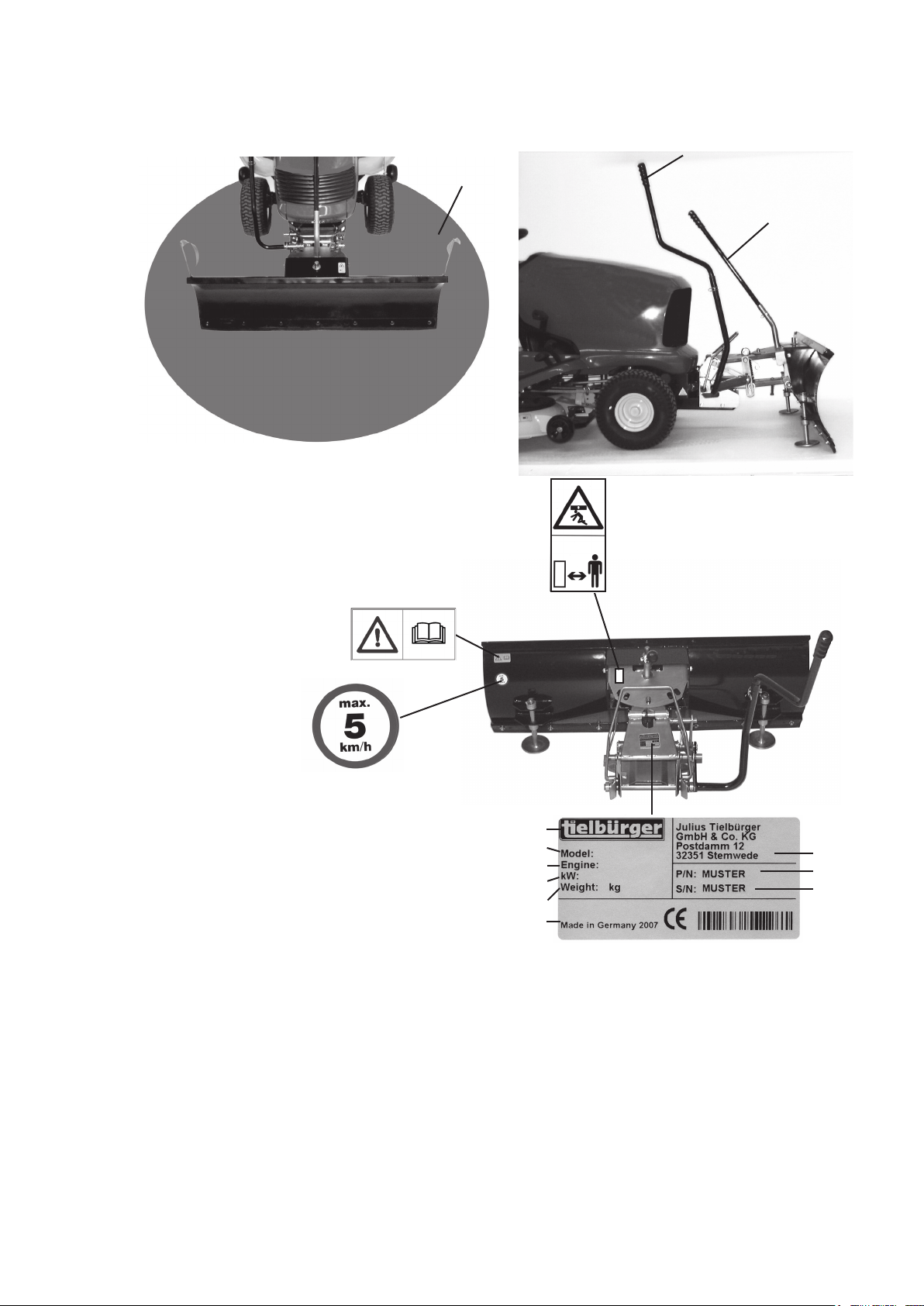
Illustration of device showing danger area
4 Illustration of device showing danger area, description of components, position of safety stickers and identication plate
5
1. Danger area
2. Lever for raising and lowering the shovel blade
3. Lever for adjusting angle of shovel blade
4. Manufacturer’s name
5. CE mark
6. Machine number
7. Machine designation
8. Weight
9. Year of manufacture
10. Adress of manufacturer
11. Engine manufacturer
12. Engine output
13. Part number
2
3
4
7
11
12
8
9
Before operating the equip-
ment, read and observe the
operating and safety instruc-
tions.
Max. speed 5 km/h
1
Do not stand in the vicinity of a
raised, unsecured load.
10
13
6
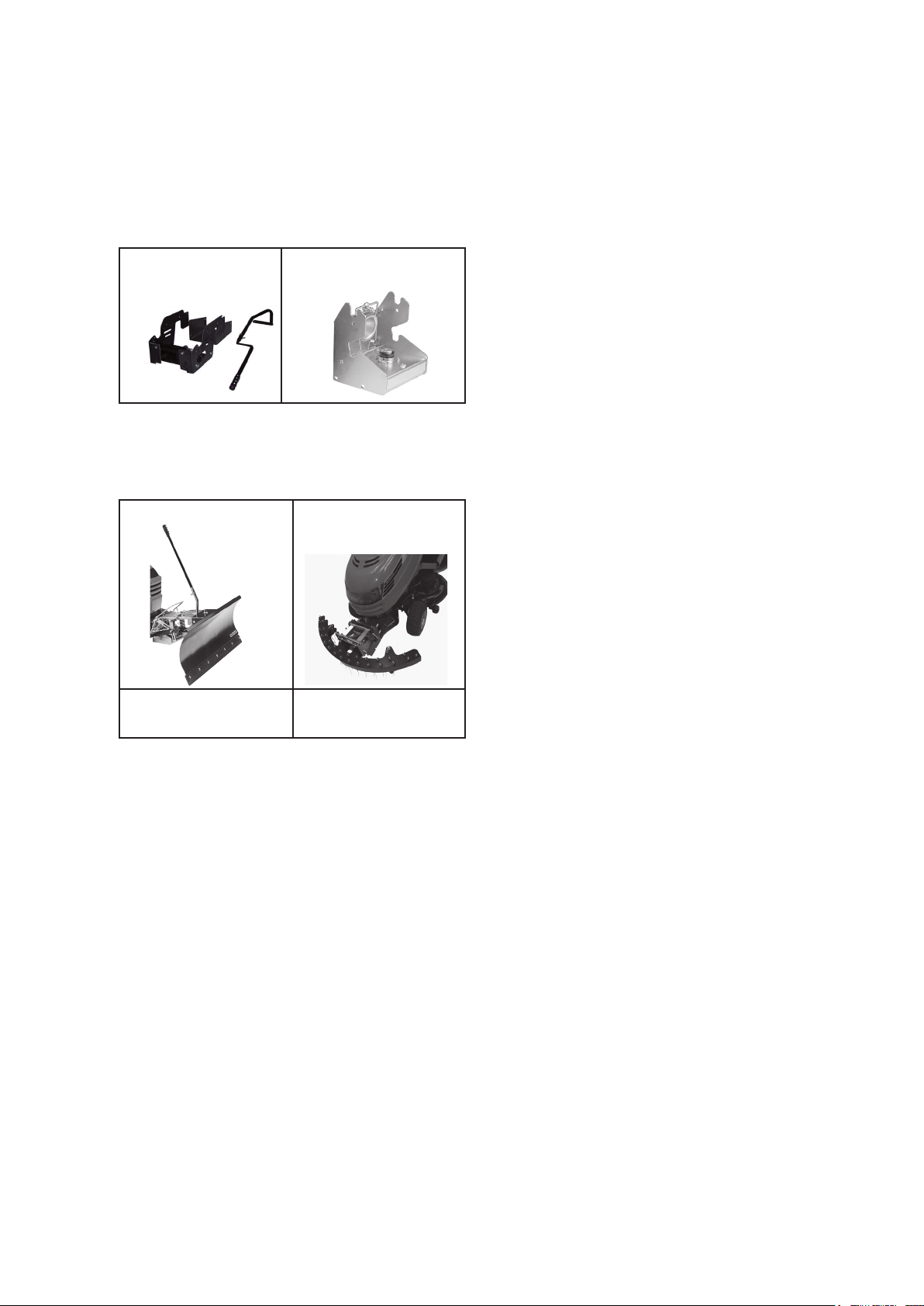
5.2 Components of the quick-release system
5.1 Attachment sets for tractor mowers
Condition at delivery and scope of delivery
10
Quick-release coupling with
drive
Add-on parts
1
2
5.3 Accessories
10
1 + 2
1 + 2
Clearing plate ts125
Please ask your dealer for further accessories.
You can get more information on the internet at :www.tielbuerger.de
required at least
required at least
Attachment components and quick-release couplings with or without drive system are manufactured specically
for all models of tractor mower. Ask your specialist dealer for details.
Greenkeeper 110
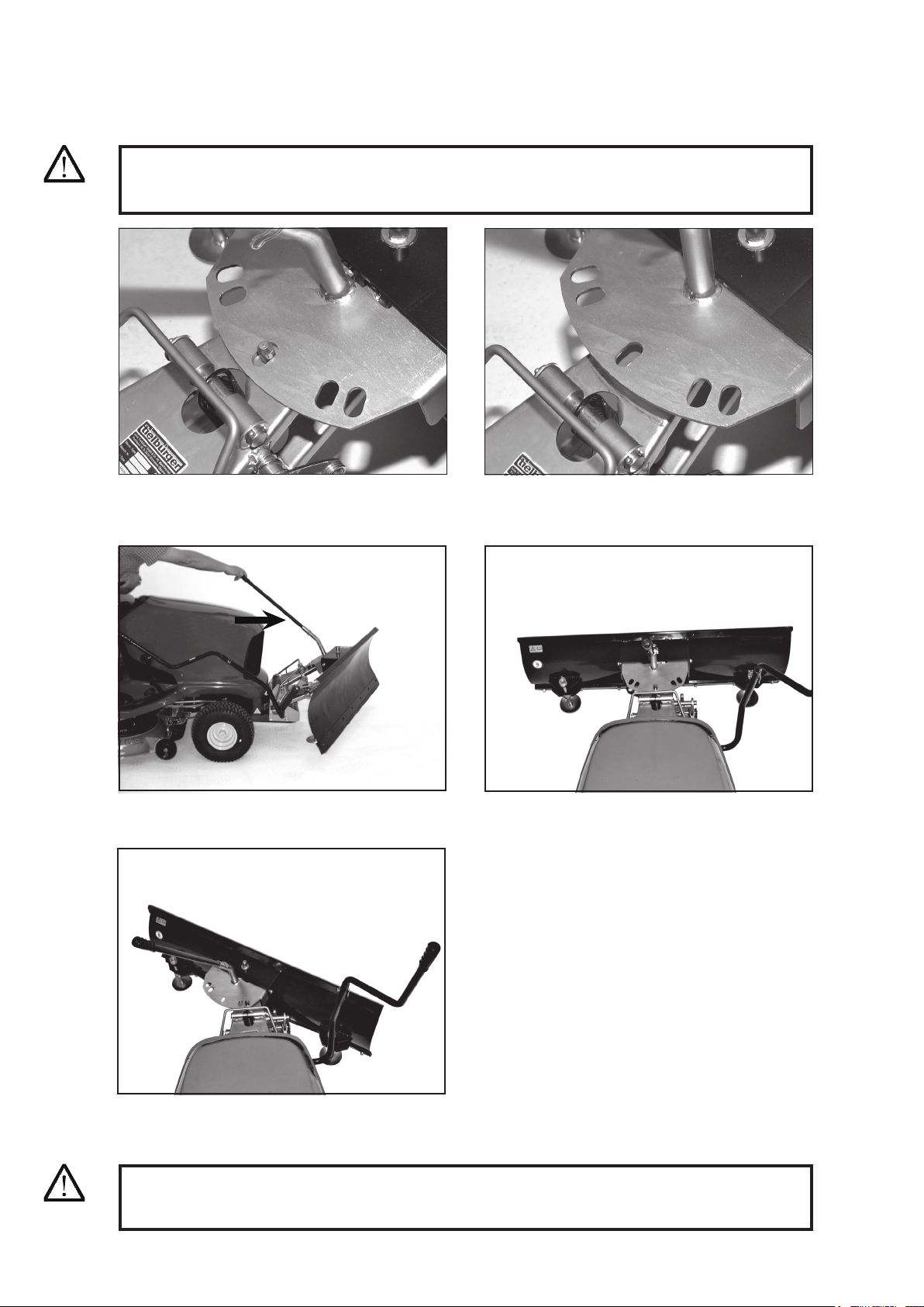
5 Components of the Tielbürger quick-release system
11
6 Assembly
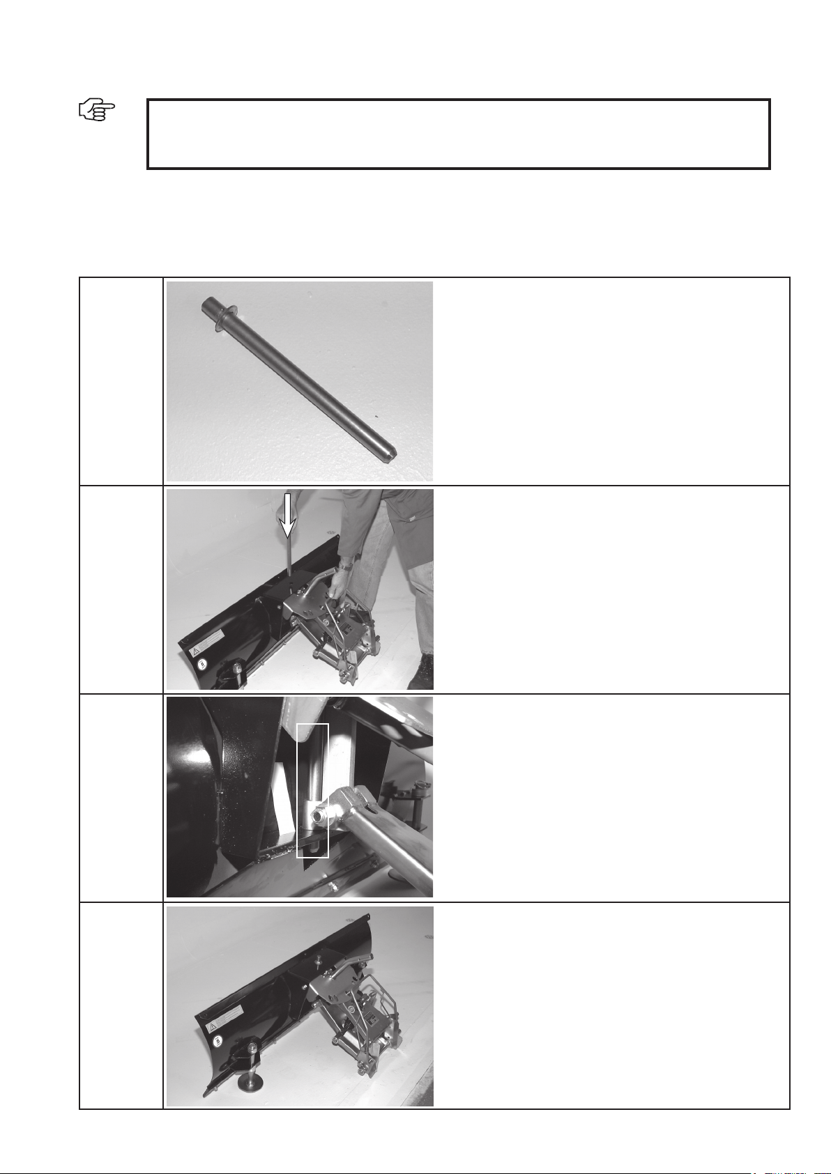
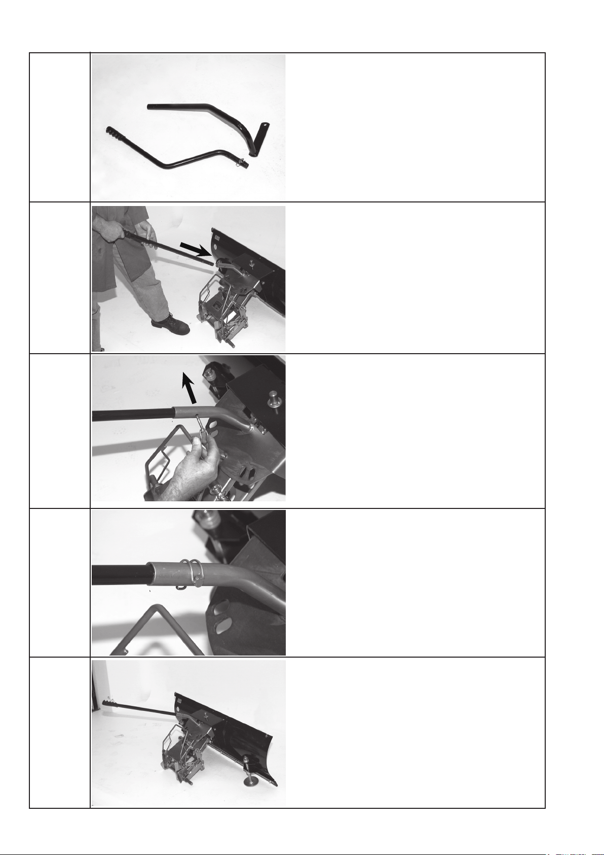
Link pin
The mounting bracket is attached to the shovel blade by
means of the link pin.
Correct position of link pin.
Assembly
Mounting bracket tted to ts125 shovel blade.
IMPORTANT !
Observe safety instructions.
Before you begin, obtain an overview of the assembly procedure and the parts and tools required.
12
Insert lever for angle setting in locating tube on posi-
tioner plate.
Secure lever with locking pin.
Fitted lever with locking pin.
Shovel blade with lever tted.
Assembly
Note: lifting linkage is part of the attachment frame.

7.1 Fundamental safety instructions for standard operation
7 Commissioning
Commissioning
13
WARNING
Observe maximum speed of 5 km/h!
Avoid any operational mode that may be prejudicial
to safety.
Before beginning work, familiarize yourself with the
location of installation and circumstances of the site.
This includes obstacles in the working and travelling
area, the earth load capacity and any barriers separating
the location of installation from public roads.
Take the necessary precautions to ensure that the
machine is used only when in a safe and reliable state.
Operate the machine only if all protective and safety-
oriented devices, such as removable safety devices,
sound-proong elements and exhausters, are in place
and fully functional.
Check the machine for obvious damage and faults each
time you use it. Report any changes (incl. changes in
the machine’s working behaviour) to a specialized
dealer. If necessary, stop the machine immediately
and lock it.
In the event of malfunctions, stop the machine im-
mediately and lock it. Have any defects rectified
immediately.
Start the machine from the driver’s seat only.
During start-up and shut-down procedures always
watch the indicators in accordance with the operating
and assembly instructions.
Before starting up or setting the machine in motion,
make sure that nobody is at risk.
Before starting work or travelling with the machine,
check that the braking, steering, signalling and lighting
systems are fully functional.
Before setting the machine in motion always check that
the accessories have been safely stowed away.
When driving on public roads, pathways or open
spaces, observe the applicable trafc regulations and,
if appropriate, make the necessary adjustments to the
machine to ensure it meets the legal requirements.
In conditions of poor visibility and after dark always
ensure that there is sufcient lighting.
Always keep at a distance from the edges of building
pits and slopes.
Avoid any operation that might be a risk to machine
stability.
Never travel across slopes; always keep the working
equipment and the load close to the ground, especially
when travelling downhill.
On sloping terrain always adapt your travelling speed
to the prevailing ground conditions. Never change to
a lower gear on a slope but always before reaching it.
Before leaving the driver’s seat always secure the
machine against inadvertent movement and unautho-
rized use.
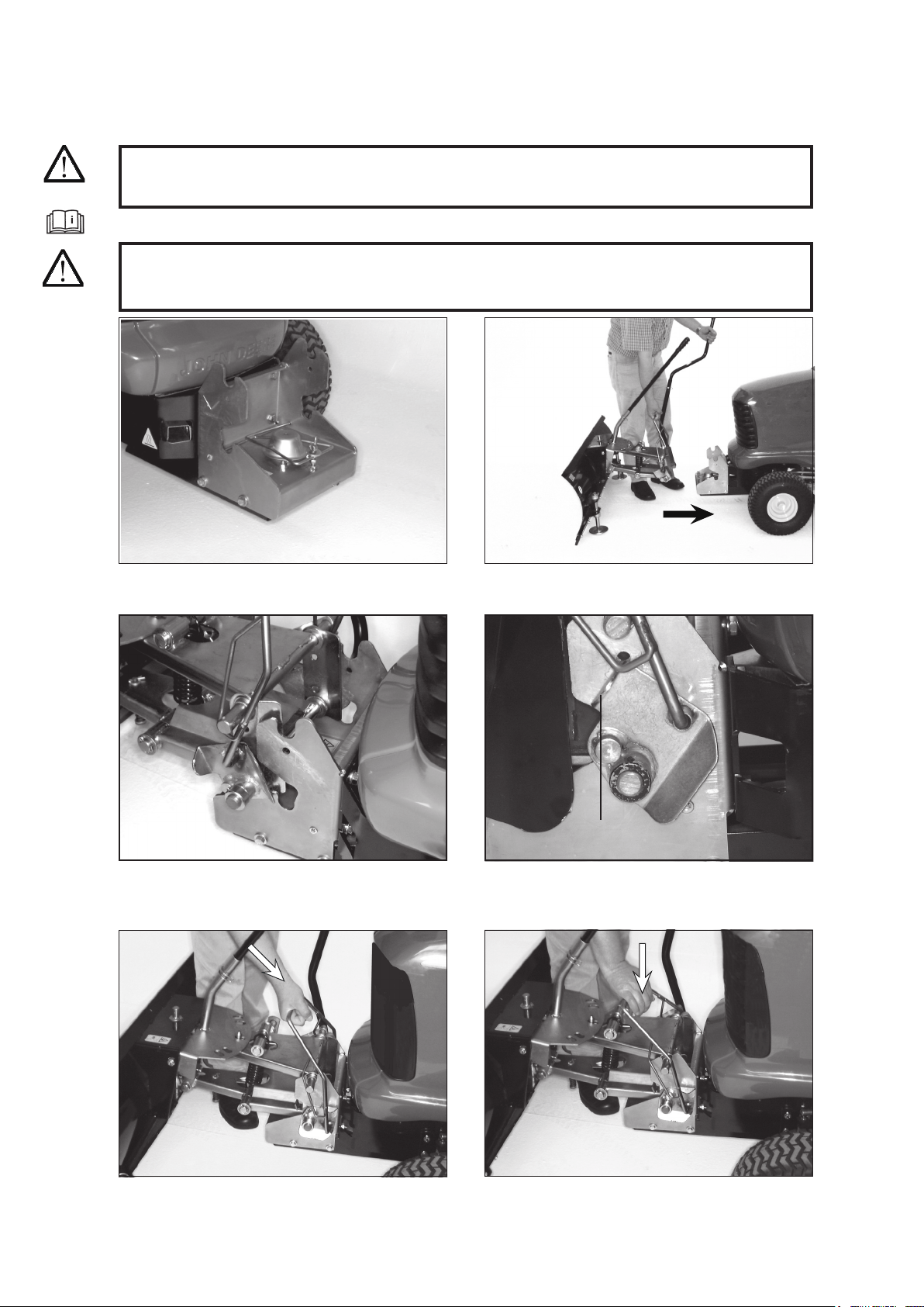
7.2 Coupling and uncoupling the shovel blade
Commissioning
14
3) Position prior to engagement. Now lift mounting
bracket and engage.
5) Press coupling hoop downwards at an angle.
4) Tongue prior to locking. Mounting bracket engaged.
6) Locking the shovel blade.
DANGER
Switch off the engine. Secure the tractor mower to prevent it moving and take precautions to ensure
it cannot be started inadvertently.
1) The quick-release coupling safety cover must be
closed.
2) Hold the lifting lever with your left hand.
Pull shovel blade attachment towards tractor mower.
WARNING
If the drive system is not being used, the quick-release coupling safety cover must be secured by
the wing nut.
Read the operating instructions supplied by the tractor mower manufacturer.
Tongue
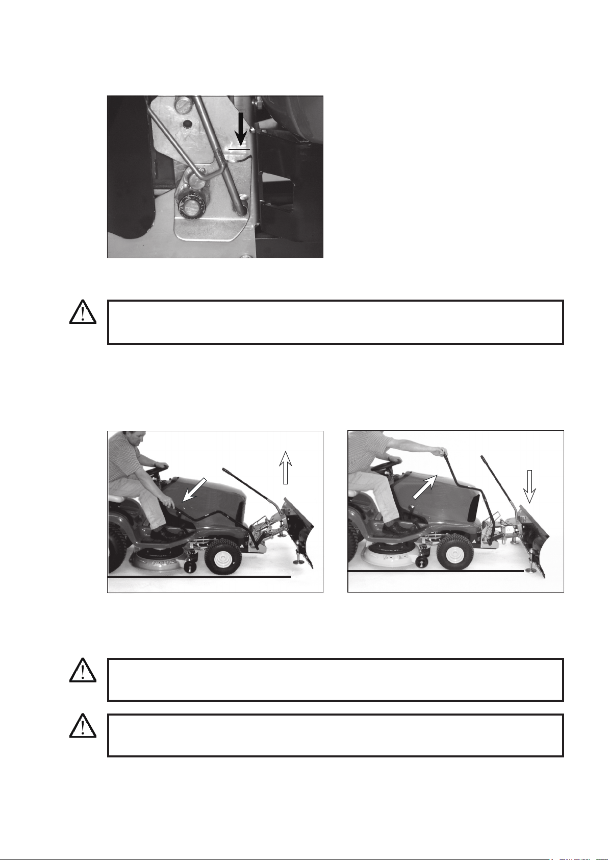
7.3 Raising and lowering the shovel blade
Commissioning
2) To lower the shovel blade attachment, move the
lever up.
15
1) To raise the shovel blade attachment, press the
lever down.
WARNING
Make sure there are no people or objects in the danger area. Otherwise personal injury or
damage to property could result.
7) Correctly locked. The tongue must be pushed as
far as the horizontal notch.
Uncoupling the shovel blade attachment is the reverse procedure.
When uncoupling, hold the shovel blade securely by the lifting lever so that it doesn’t tip forwards.
WARNING
Before using the shovel blade attachment, make absolutely certain that the quick-release coupling
is securely locked.
WARNING
Do not stand in the vicinity of a raised, unsecured shovel blade. When not in use, the shovel
blade must be in the fully lowered position.
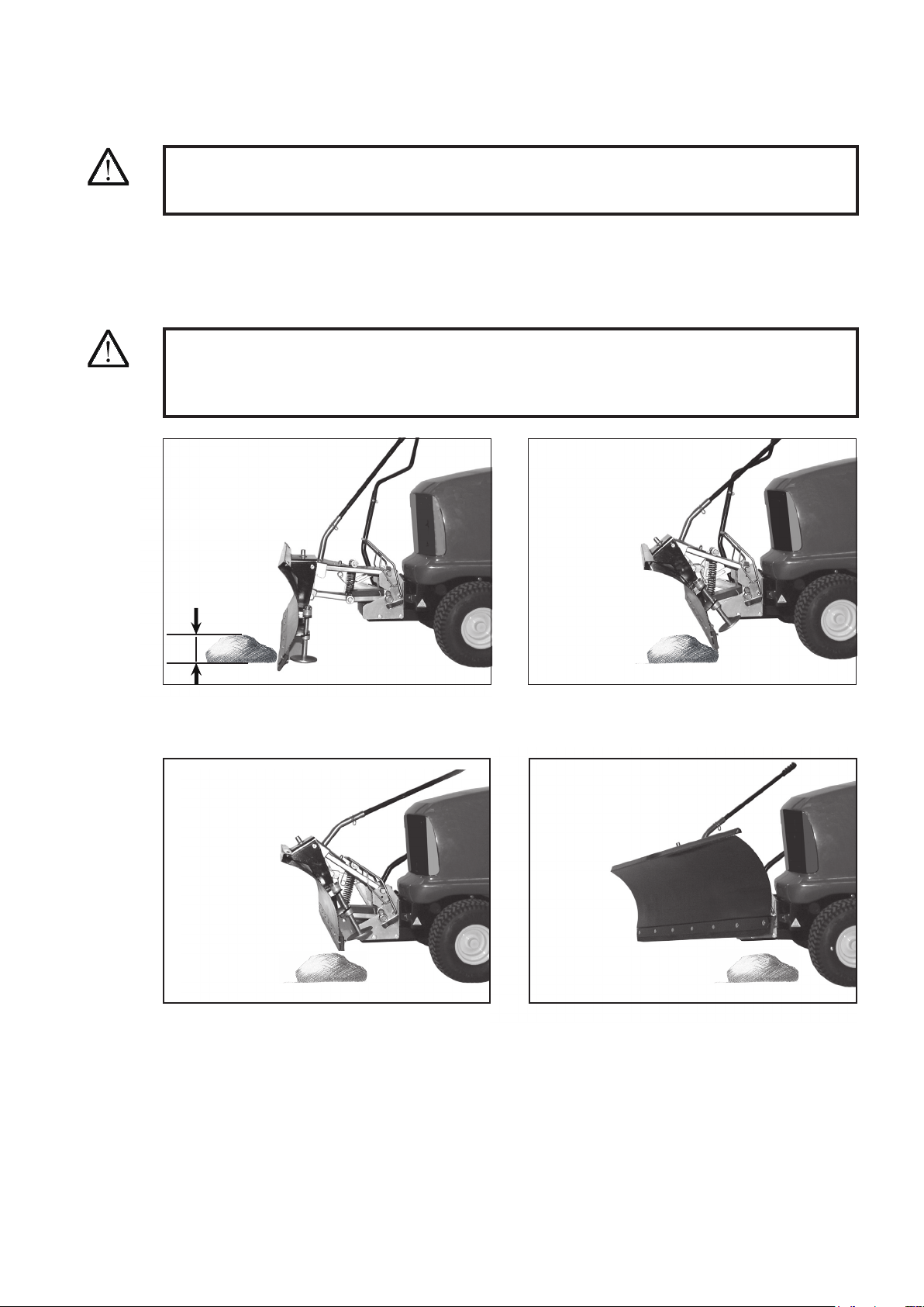
7.4 Angling the shovel blade
Commissioning
16
2) Positioner plate with ve angle settings. To adjust
the blade angle, the operating rod has to be lifted
up.
WARNING
Make sure there are no people or objects in the danger area. Otherwise personal injury or damage
to property could result.
1) Basic setting. Shovel blade facing straight ahead.
Pin locks shovel blade in position.
3) Lift the operating rod and turn the shovel blade to
the desired angle.
4) This setting is recommended for piling up.
5) Sideways angle settings are suitable for pushing
material to the side.
Photo shows blade angle set to right.
WARNING
Do not stand in the vicinity of a raised, unsecured shovel blade. When not in use, the shovel
blade must be in the fully lowered position.
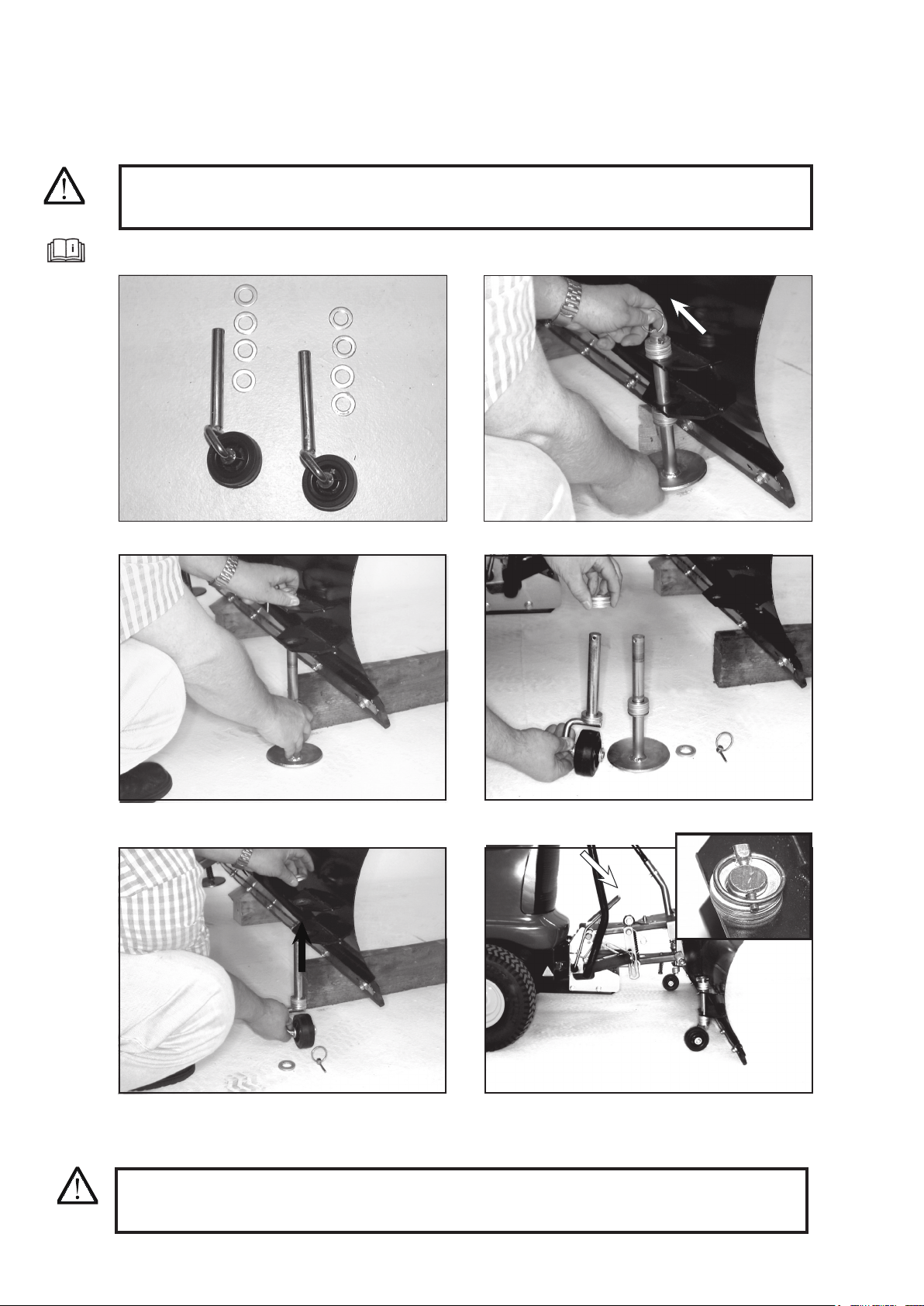
7.5 Adjusting the height of the skids
Commissioning
17
2) Remove folding pin.
3) Pull skid downwards and remove.
4) The height setting of the skids is adjusted by repo-
sitioning the shims.
1) Raise the shovel blade slightly and place two woo-
den blocks under the blade.
DANGER
Switch off the engine. Secure the tractor mower to prevent it moving and take precautions to ensure
it cannot be started inadvertently.
5) When the skid height has been adjusted, the skid is
slid upwards through the guides and secured using
the folding pin. Repeat the procedure for the left-
hand skid.
Read the operating instructions supplied by the tractor mower manufacturer.
6) Raise the shovel blade slightly and remove the
wooden blocks. The gap between the ground and
the rubber strip should be 2 - 3 mm.
WARNING
Do not stand in the vicinity of a raised, unsecured shovel blade. When not in use, the shovel
blade must be in the fully lowered position.
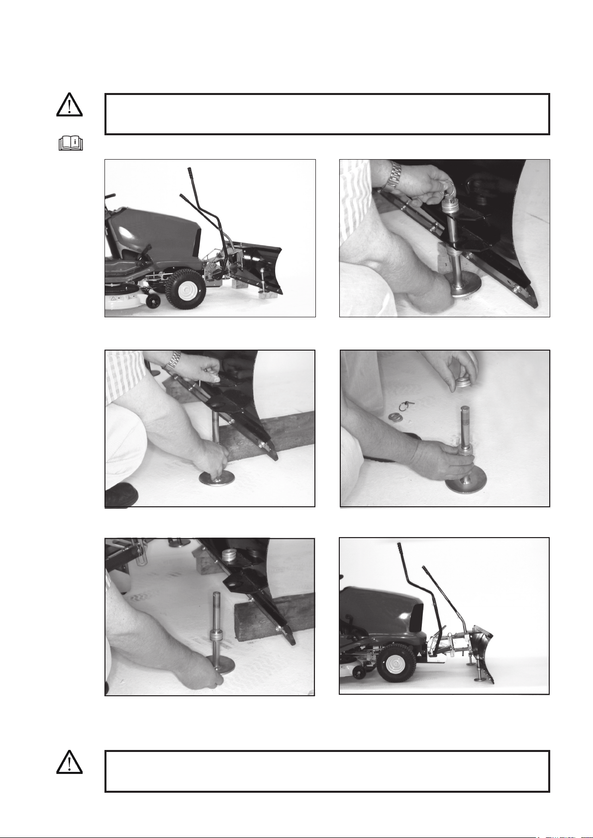
7.6 Fitting wheels (optional extra)
Commissioning
18
DANGER
Switch off the engine. Secure the tractor mower to prevent it moving and take precautions to ensure
it cannot be started inadvertently.
2) Raise shovel blade. Remove folding pin.
1) Wheels and shims.
3) Pull skid downwards and remove. 4) Remove shims from skids and t to wheels.
5) Slide wheel upwards through the guides. Repeat
the procedure for the left-hand wheels.
6) Secure wheel with folding pin. The gap between
the ground and the rubber strip should be 2 - 3 mm.
Read the operating instructions supplied by the tractor mower manufacturer.
WARNING
Do not stand in the vicinity of a raised, unsecured shovel blade. When not in use, the shovel
blade must be in the fully lowered position.
Favourably for sensitive surfaces.
7.7 Safety folding mechanism
Commissioning
19
2) Shovel blade lower edge folds back. Safety folding
mechanism disengaged.
3) The blade also lifts upwards from the ground. 4) The angle setting mechanism is released and the
shovel blade clears the obstacle.
1) Shovel blade strikes an obstruction.
WARNING
The safety folding mechanism only functions with obstructions with a maximum height of 7 cm.
Observe maximum speed of 5 km/h!
The shovel blade is tted with a safety folding mechanism. It is intended to prevent injury to the driver and damage
to the tractor mower if the blade strikes an obstruction. Compared to other safety systems on shovel blades, the
force transmitted to the driver and tractor mower is substantially smaller.
Please note that this is an emergency device. Do not therefore drive carelessly, always think ahead and look out
for obstructions such as manhole covers, edging stones and tree stumps, etc.
DANGER
If the shovel blade does not return to its original position after striking an obstruction, attempt to raise
it using the lifting lever. Do not reach inside the safety folding mechanism as there is a risk of your
ngers/hand becoming trapped.
Max. 7 cm

Service and maintenance
8.1 Fundamental safety instructions
8 Service and maintenance
IMPORTANT
Pay attention to the following:
• fuel and oil leaks, rectify if necessary
• snug t of bolts and nuts, tighten if necessary
• ease of movement of all moving parts, lubricate if necessary
20
Observe the adjusting, maintenance and inspection
activities and intervals set out in the operating instruc-
tions, including information on the replacement of
parts and equipment. These activities may be executed
by skilled personnel only. See maintenance schedule.
Brief operating personnel before beginning special
operations and maintenance work, and
appoint a person to supervise the activities.
In any work concerning the operation, conversion or
adjustment of the machine and its safety-oriented de-
vices or any work related to maintenance, inspection
and repair, always observe the start-up and shut-down
procedures set out in the operating instructions and
the information on maintenance work. Ensure that the
maintenance area is adequately secured.
If the machine is completely shut down for main-
tenance and repair work, it must be secured against
inadvertent starting by:
-removing the ignition key
-attaching a warning sign to the ignition unit.
Carry out maintenance and repair work only if the
machine is positioned on stable and level ground and
has been secured against inadvertent movement and
buckling.
To avoid the risk of accidents, individual parts and
large assemblies being moved for replacement purpo-
ses should be carefully attached to lifting tackle and
secured. Use only suitable and technically perfect lif-
ting gear and suspension systems with adequate lifting
capacity. Never work or stand under suspended loads.
Never use machine parts as a climbing aid.
Keep all handles and steps free from dirt, snow and ice.
Clean the machine, especially connections and threa-
ded unions, of any traces of oil, fuel or preservatives
before carrying out maintenance/repair. Never use
aggressive detergents. Use lint-free cleaning rags.
Before cleaning the machine with water, high-pressure
cleaner or detergents, cover or tape up all openings
which - for safety and functional reasons - must be
protected against water, steam or detergent penetration.
Special care must be taken with electric motors and
other components under voltage.
After cleaning, remove all covers and tapes applied
for that purpose.
After cleaning, examine all fuel and oil lines for leaks,
loose connections, chafe marks and damage. Any de-
fects found must be rectied without delay.
Always tighten any screwed connections that have been
loosened during maintenance and repair.
Any safety devices removed for set-up, maintenance
or repair purposes must be retted and checked im-
mediately upon completion of the maintenance and
repair work.
Ensure that all consumables and replaced parts are
disposed of safely and with minimum environmental
impact.
The electrical equipment of machines is to be inspec-
ted and checked at regular intervals. Defects such as
loose connections or scorched cables must be rectied
immediately.
Before starting work on high-voltage assemblies and
after cutting out the power supply, the power cable
must be grounded and components such as capacitors
short-circuited with a grounding rod.
Never leave internal combustion engines to run in a
closed or small room. The exhaust gas contains poiso-
nous carbon monoxide.
Observe the regulations in force at the respective site.
Carry out welding, ame-cutting and grinding work on
the machine only if this has been expressly authorized,
i.e. there may be a risk of re or explosion!
Before carrying out welding, ame-cutting and grin-
ding operations, clean the machine and its surroundings
from dust and other inammable substances and make
sure that the premises are adequately ventilated (risk
of explosion).
Check all lines, hoses and screwed connections regu-
larly for leaks and obvious damage. Repair damage
immediately. Splashed oil may cause injury and re.
During operation, all sound bafes must be closed.
Always wear the prescribed ear protectors. When
handling oil, grease and other chemical substances,
observe the product-related safety regulations.
Be careful when handling hot consumables (risk of
burning or scalding).

Possible faults and their elimination
9 Possible faults and their elimination
Fault Remedy
Tyres spin
Shovel blade leaves too much
snow behind
Set shovel blade at greater angle. Fit snow chains.
Adjust the height of the skids.
21
IMPORTANT
Should a fault occur that is not listed in this table, consult a specialized dealer. If all remedies
described here have been unsuccessful, consult a specialized dealer.
IMPORTANT
Use only original spare parts from the manufacturer that are available from your specialized
dealer. These will ensure that the machine functions correctly.
Check bolts and nuts
Check engine air lter and clean if necessary
F = Serviced by specialist dealer
K = Checked by operator
W = Serviced by operator
Before
using,
After every ... hours of service
At least
every 3
months
At least
once a
year
After
cleaning,
always ...
5 10 25 50 100
K
K
IMPORTANT
Observe the manufacturer’s servicing instructions for the tractor mower.
8.2 Service schedule
The manufacturer’s terms of guarantee are valid in the
territory of the Federal Republic of Germany.
This guarantee applies if the appliance is used correctly
in accordance with its intended purpose, if it is treated
in a proper manner and if the information contained in
the operating instructions is followed.
This guarantee does not cover damage arising s a result
of
normal wear and tear of working parts, such as
10 Terms of Guarantee
lter elements, spark plugs, tyres, light bulbs, friction
linings, fan belts, blades, improper treatment, negligent
use, installation of non-original spare parts, insufcient
care and/or maintenance, or non-compliance with the
operating instructions.
Outside the Federal Republic of Germany, the terms
of guarantee published by our local state agency apply.
2222
Spare parts list
11 Spare parts list
Important
Under „remarks“ you will be able to identify the parts. Please use only genuine spare parts of the
manufakturer. Only this way, a safe operation of the machine is guaranteed. Item numbers in par-
entheses are wearing parts.
Spare parts list
23

12 Manufacturer‘s declaration
24
Manufacturer: Julius Tielbürger GmbH & Co.KG
Maschinenfabrik
Postdamm 12
D-32351 Stemwede-Oppenwehe
Note:
Combined with the Tielbürger system, the device described in this instruction
manual conforms to the denition of interchangeable equipment in accordance
with the Machinery Directive 2006/42/EC.
The device may only be used as described in this instruction manual.
It is prohibited to use this device in any way not described in this instruction
manual! The conformity declaration is documented in the instruction manual
for the corresponding Tielbürger system.
KR-392-002GI