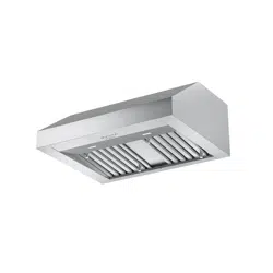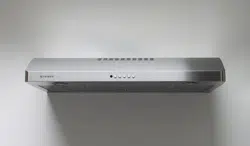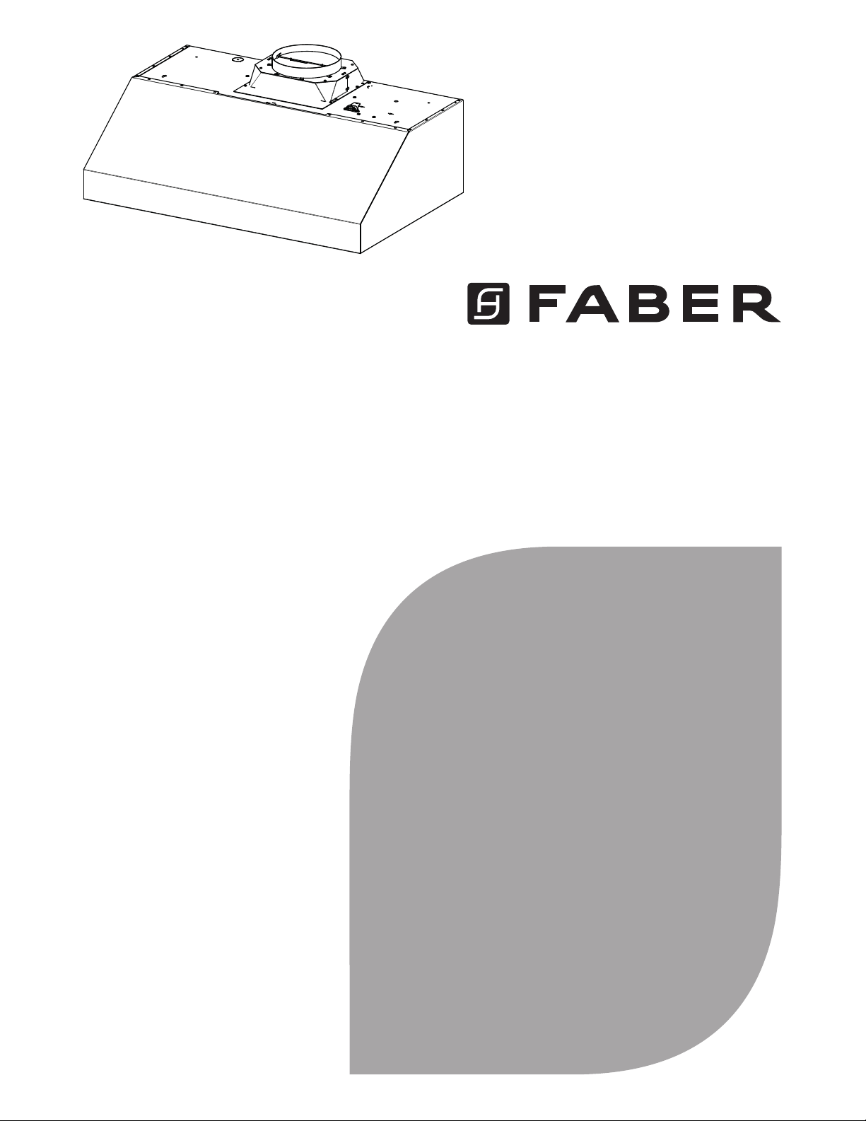
BREV301SS600
BREV368SS600
Installation Instructions
Use and Care Information
Instructions d'installation
Utilisez et d'entretien
Instrucciones de instalación
Información de uso y cuidado
BREVA PRO 11

2
CONTENTS
Section Page
Important safety instructions
3
Range hood dimensions
6
Installation height requirements
7
Tools needed
7
Parts
8
Venting method
12
Mount the Motor into the hood
13
Mount the SPACER (ONLY FOR BREVA 30)
17
Recirculation instructions
18
Mounting on the wall
19
Installation for Mounting Under the Cabinet
23
Connecting house power
25
Operating the controls
26
CFM adjustment < 295CFM
29
CFM adjustment < 395CFM
30
Faber cloud app
31
Remote control
32
Cleaning stainless steel
32
Caring for filters
33
Replacing the activated charcoal filter
34
Replacing bulbs
34
Wiring diagram
35
Warranty
36

3
IMPORTANT SAFETY INSTRUCTIONS
READ AND SAVE THESE INSTRUCTIONS BEFORE YOU START
INSTALLING THIS Range Hood
WARNING: - TO REDUCE THE RISK OF A RANGE TOP GREASE FIRE:
a) Never leave surface units unattended at high settings. Boilovers cause smoking and greasy
spillovers that may ignite. Heat oils slowly on low or medium setting.
b) Always turn hood ON when cooking at high heat or when flambeing food (i.e. Crepes
Suzette, Cherries Jubilee, Peppercorn Beef Flambé).
c) Clean ventilating fans frequently. Grease should not be allowed to accumulate on fan or
filter.
d) Use proper pan size. Always use cookware appropriate for the size of the surface element.
WARNING: - TO REDUCE THE RISK OF INJURY TO PERSONS IN THE EVENT OF A RANGE
TOP GREASE FIRE, OBSERVE THE FOLLOWING*:
a) SMOTHER FLAMES with a close-fitting lid, cookie sheet, or metal tray, then turn off the
burner. BE CAREFUL TO PREVENT BURNS. If the flames do not go out immediately
EVACUATE AND CALL THE FIRE DEPARTMENT.
b) NEVER PICK UP A FLAMING PAN - You may be burned.
c) DO NOT USE WATER, including wet dishcloths or towels - a violent steam explosion will
result.
d) Use an extinguisher ONLY if:
1. You know you have a Class ABC extinguisher, and you already know how to operate
it.
2. The fire is small and contained in the area where it started.
3. The fire department is being called.
4. You can fight the fire with your back to an exit.
* Based on "Kitchen Firesafety Tips" published by NFPA
WARNING - TO REDUCE THE RISK OF FIRE OR ELECTRIC SHOCK, do not use this fan with
any solid-state speed control device.
WARNING - TO REDUCE THE RISK OF FIRE, ELECTRICAL SHOCK, OR INJURY TO PERSONS,
OBSERVE THE FOLLOWING:
1. Use this unit only in the manner intended by the manufacturer. If you have any questions,
contact the manufacturer.
2. Before servicing or cleaning unit, switch power off at service panel and lock the service
disconnecting means to prevent power from being switched on accidentally. When the
service disconnecting means cannot be locked, securely fasten a prominent warning
device, such as a tag, to the service panel.
CAUTION: For General Ventilating Use Only. Do Not Use To Exhaust Hazardous or Explosive
Materials and Vapors.
WARNING - TO REDUCE THE RISK OF FIRE, ELECTRICAL SHOCK, OR INJURY TO PERSONS,
OBSERVE THE FOLLOWING:
1. Installation Work And Electrical Wiring Must Be Done By Qualified Person(s) In Accor-
dance With All Applicable Codes And Standards, Including Fire-Rated Construction.
2. Sufficient air is needed for proper combustion and exhausting of gases through the
flue (chimney) of fuel burning equipment to prevent backdrafting. Follow the heating
equipment manufacturer's guideline and safety standards such as those published by
the National Fire Protection Association (NFPA), and the American Society for Heating,
Refrigeration and Air Conditioning Engineers (ASHRAE), and the local code authorities.
4
ALL WALL AND FLOOR OPENINGS WHERE THE Range Hood IS INSTALLED MUST
BE SEALED.
This Range Hood requires at least 24" of clearance between the bottom of the Range Hood
and the cooking surface or countertop. This hood has been approved by UL at this distance
from the cooktop.
This minimum clearance may be higher depending on local building codes. For gas cooktops
and combination ranges, a minimum of 30" is recommended and may be required.
Overhead cabinets on both sides of this unit must be a minimum of 18" above the cooking
surface or countertop. Consult the cooktop or range installation instructions given by the
manufacturer before making any cutouts.
MOBILE HOME INSTALLATION The installation of this Range Hood must conform to the
Manufactured Home Construction and Safety Standards, Title 24 CFR, Part 3280 (formerly
Federal Standard for Mobile Home Construction and Safety, Title 24, HUD, Part 280). See
Electrical Requirements"
• Venting system MUST terminate outside the home.
• DO NOT terminate the ductwork in an attic or other enclosed space.
• DO NOT use 4" laundry-type wall caps.
• Flexible-type ductwork is not recommended.
• DO NOT obstruct the flow of combustion and ventilation air.
• Failure to follow venting requirements may result in a fire.
WARNING
!
!
!
!
VENTING REQUIREMENTS
Determine which venting method is best for your application. Ductwork can extend either
through the wall or the roof.
The length of the ductwork and the number of elbows should be kept to a minimum to pro-
vide efficient performance. The size of the ductwork should be uniform. Do not install two
elbows together. Use duct tape to seal all joints in the ductwork system. Use caulking to seal
exterior wall or floor opening around the cap.
Flexible ductwork is not recommended. Flexible ductwork creates back pressure and air
turbulence that greatly reduces performance.
Make sure there is proper clearance within the wall or floor for exhaust duct before making
cutouts. Do not cut a joist or stud unless absolutely necessary. If a joist or stud must be cut,
then a supporting frame must be constructed.
WARNING - To Reduce The Risk Of Fire, Use Only Metal Ductwork.
CAUTION - To reduce risk of fire and to properly exhaust air, be sure to duct air outside
– Do not vent exhaust air into spaces within walls or ceilings or into attics, crawl spaces,
or garages.
Cold Weather installations
An additional back draft damper should be installed to minimize backward cold air flow and a nonmetallic
thermal break should be installed to minimize conduction of outside temperatures as part of the vent
system. The damper should be on the cold air side of the thermal break. The break should be as close
as possible to where the vent system enters the heated portion of the house.
3. When cutting or drilling into wall or ceiling, do not damage electrical wiring and other
hidden utilities.
4. Ducted fans must always be vented to the outdoors.
5
ELECTRICAL REQUIREMENTS
A 120 volt, 60 Hz AC-only electrical supply is required on a separate 15 amp fused circuit. A
time-delay fuse or circuit breaker is recommended. The fuse must be sized per local codes
in accordance with the electrical rating of this unit as specified on the serial/rating plate
located inside the unit near the field wiring compartment.
• Electrical ground is required on this Range Hood.
• If cold water pipe is interrupted by plastic, nonmetallic gaskets or other
materials, DO NOT use for grounding.
• DO NOT ground to a gas pipe.
• DO NOT have a fuse in the neutral or grounding circuit. A fuse in the neutral
or grounding circuit could result in electrical shock.
• Check with a qualified electrician if you are in doubt as to whether the Range
Hood is properly grounded.
• Failure to follow electrical requirements may result in a fire.
WARNING
!
!
!
!
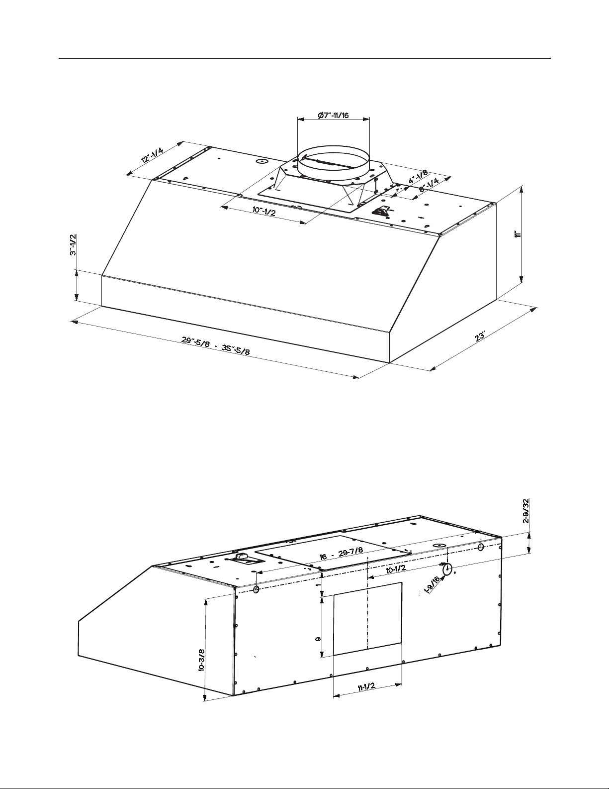
6
RANGE HOOD DIMENSIONS
36"
30"
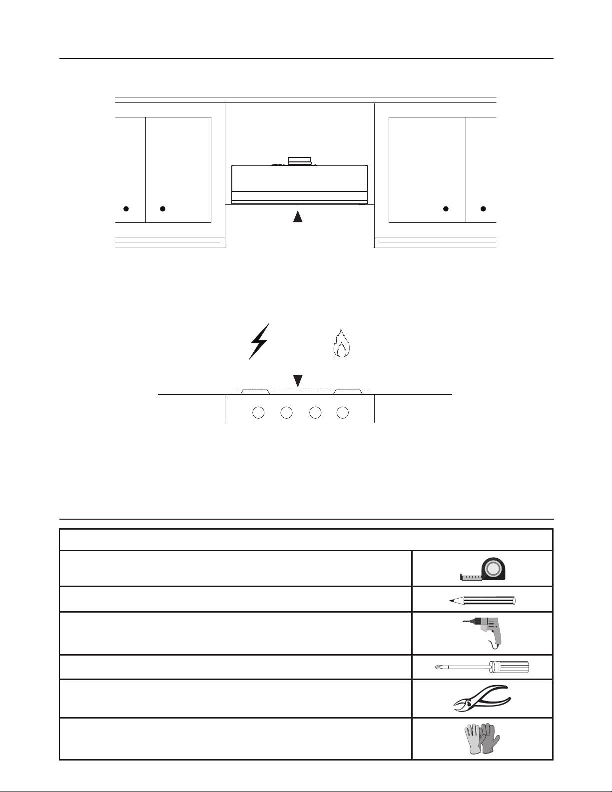
7
INSTALLATION HEIGHT REQUIREMENTS
MIN. 24" OVER ELECTRIC / MIN. 30" OVER GAS
Min.24" Min.30"
TOOLS NEEDED
TOOL
Tape Measure
Pencil
Electric Drill with 5/16" Drill Bit
Phillips Screwdriver
Metal sheers
Work gloves
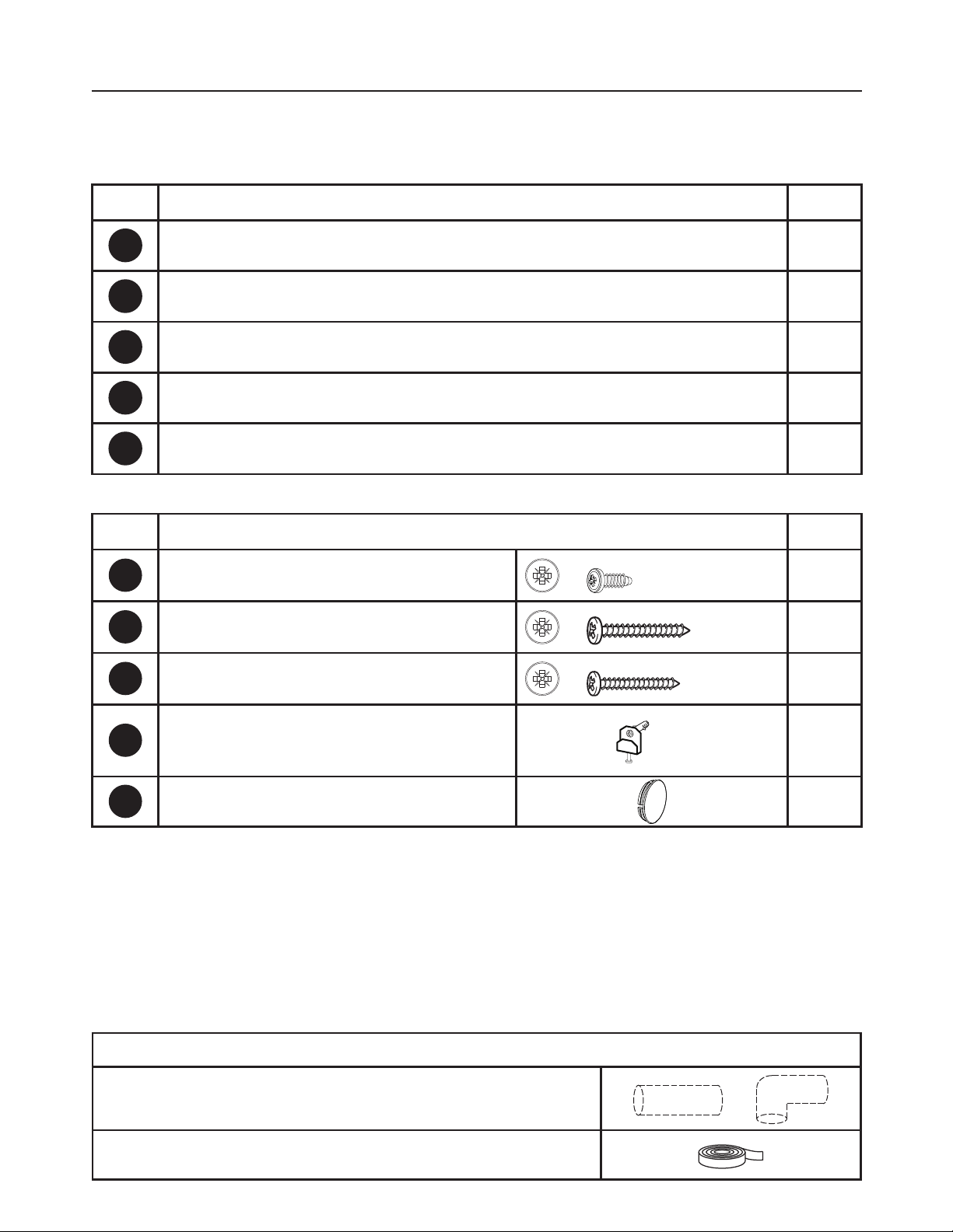
8
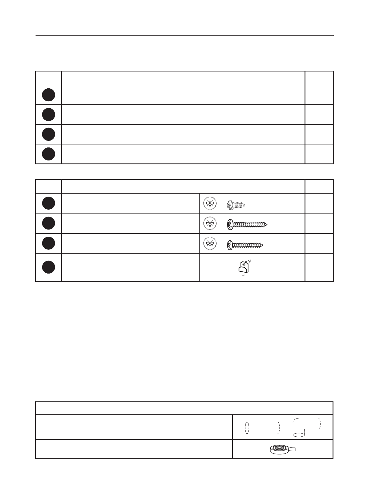
PARTS
REF. PART
QTY
A
Hood body 1
B
Grease rails 2
C
Grease filters 2
E
Damper 1
F
Spacer 1
REF
PART
G
Pozi Screws (1/8" x 3/8")
5
I
Pozi Screws (Screws 3/16" x 1 15/16")
4
L
Pozi Screws (Screws 3/16" x 1 3/4")
4
N
Wall brackets
2
M
Cap
1
PARTS INCLUDED
BREVA30
PARTS NEEDED
PART
8" Round Metal Ductwork
Foil tape
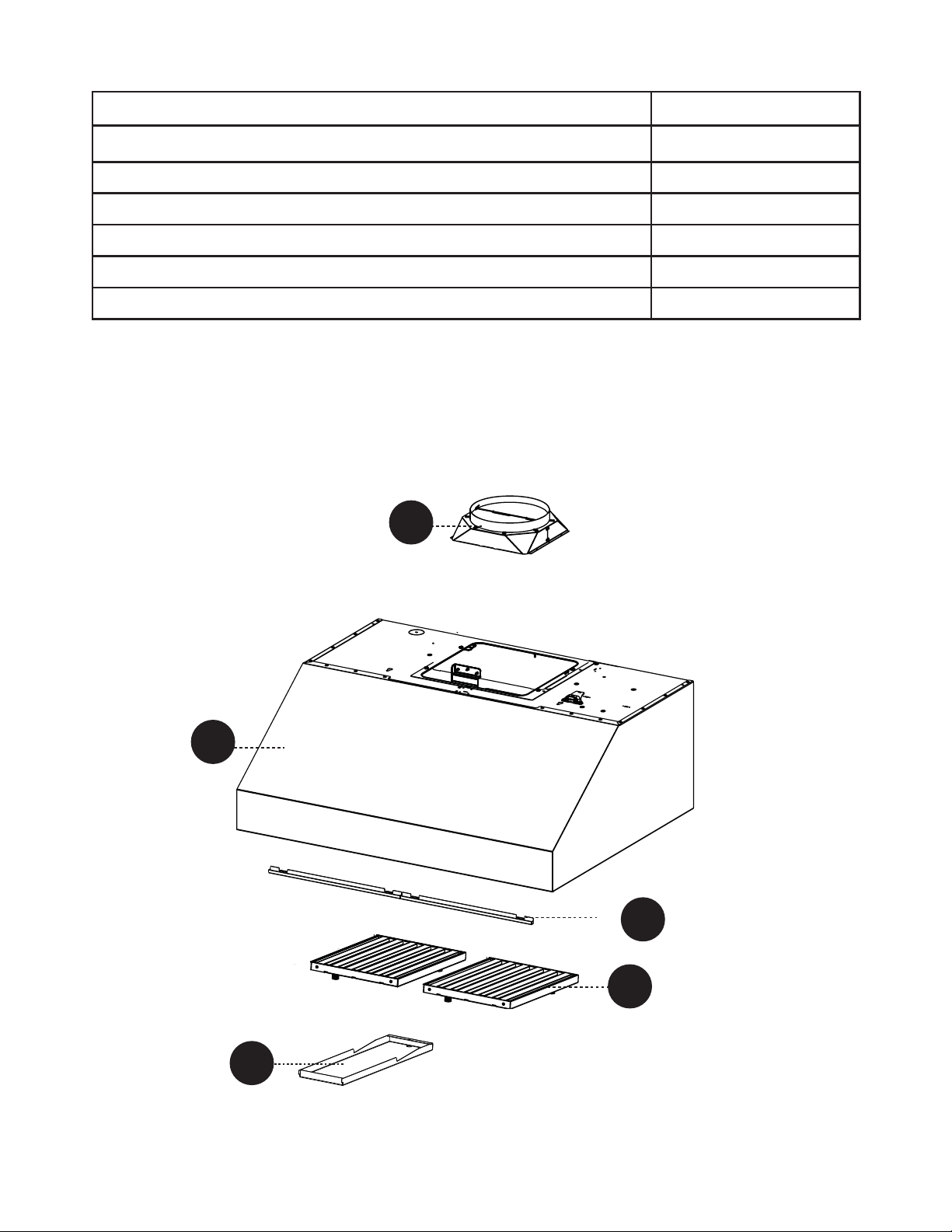
9
A
E
F
Z
B
C
ACCESSORIES AVAILABLE
ACCESSORY SKU#
TELESCOPIC PRO CHIMNEY 30 TELEPRO30
TELESCOPIC BACKSPLASH 30 BACK30
DUCTLESS KIT 30 DUCTGRT304
CHARCOAL FILTER FILTER6
FIXED WIRING BOX WIREBOX2
REMOTE CONTROL REMCTRL3
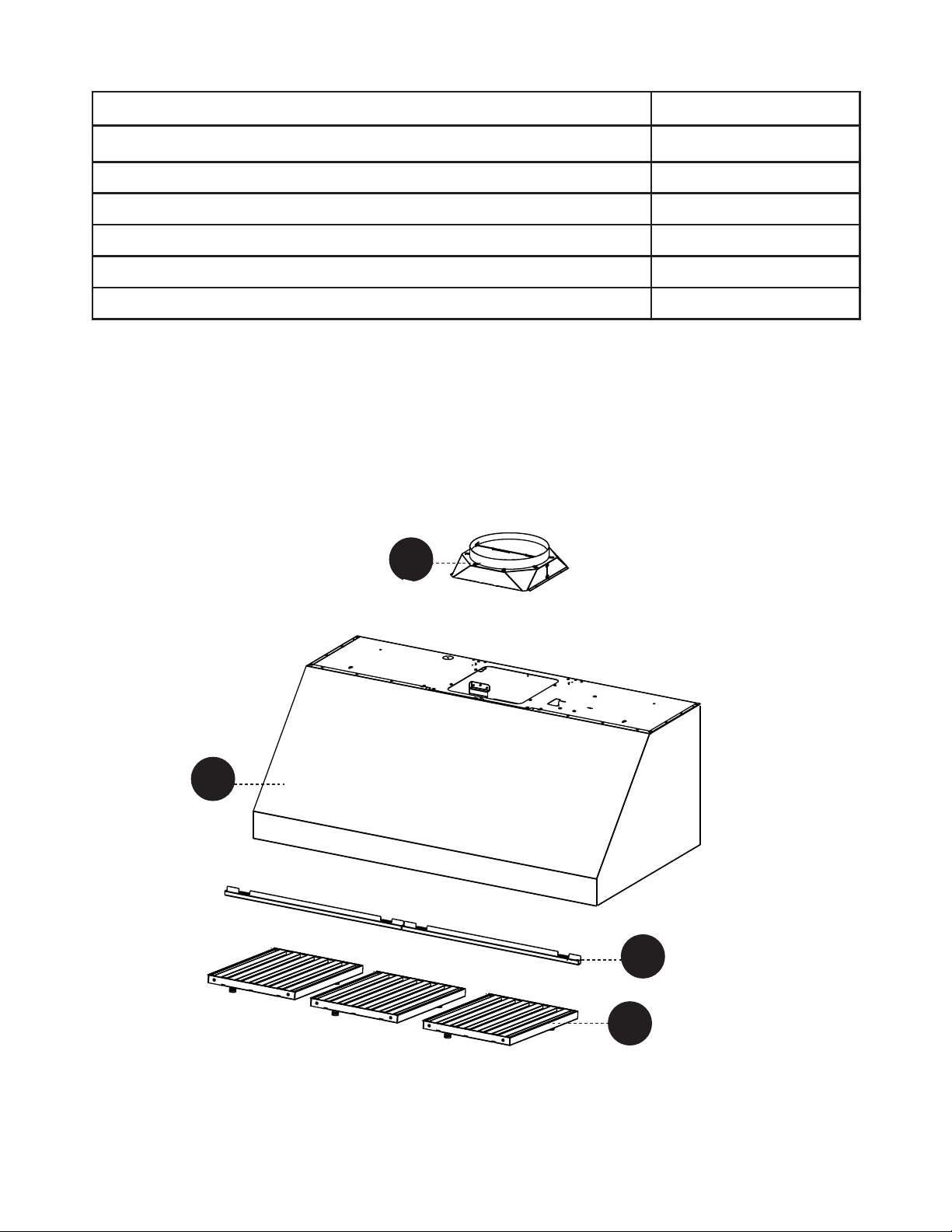
10
PARTS
REF. PART
QTY
A
Hood body 1
B
Grease rails 2
C
Grease filters 3
E
Damper 1
REF
PART
G
Pozi Screws (1/8" x 3/8")
4
I
Pozi Screws (Screws 3/16" x 1 15/16")
4
L
Pozi Screws (Screws 3/16" x 1 3/4")
4
N
Wall brackets
2
PARTS INCLUDED
BREVA36
PARTS NEEDED
PART
8" Round Metal Ductwork
Foil tape
11
A
E
Z
B
C
ACCESSORIES AVAILABLE
ACCESSORY SKU#
TELESCOPIC PRO CHIMNEY 36 TELEPRO36
TELESCOPIC BACKSPLASH 36 BACK36
DUCTLESS KIT 36 DUCTGRT364
CHARCOAL FILTER FILTER6
FIXED WIRING BOX WIREBOX2
REMOTE CONTROL REMCTRL2
12
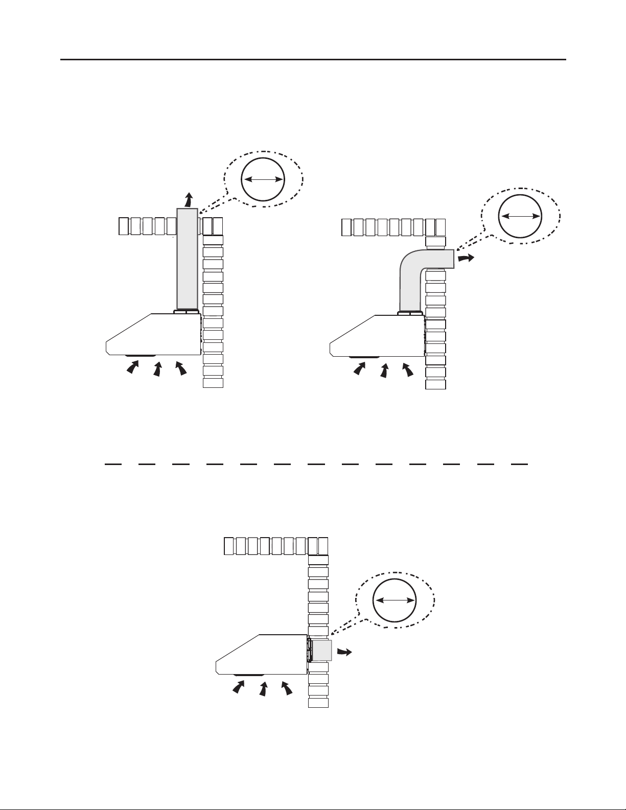
VENTING METHOD
REAR OR TOP VENTED
Horizontal
Vertical
8"
8"
Rear
8"
Go to Pg.13
Go to Pg.14
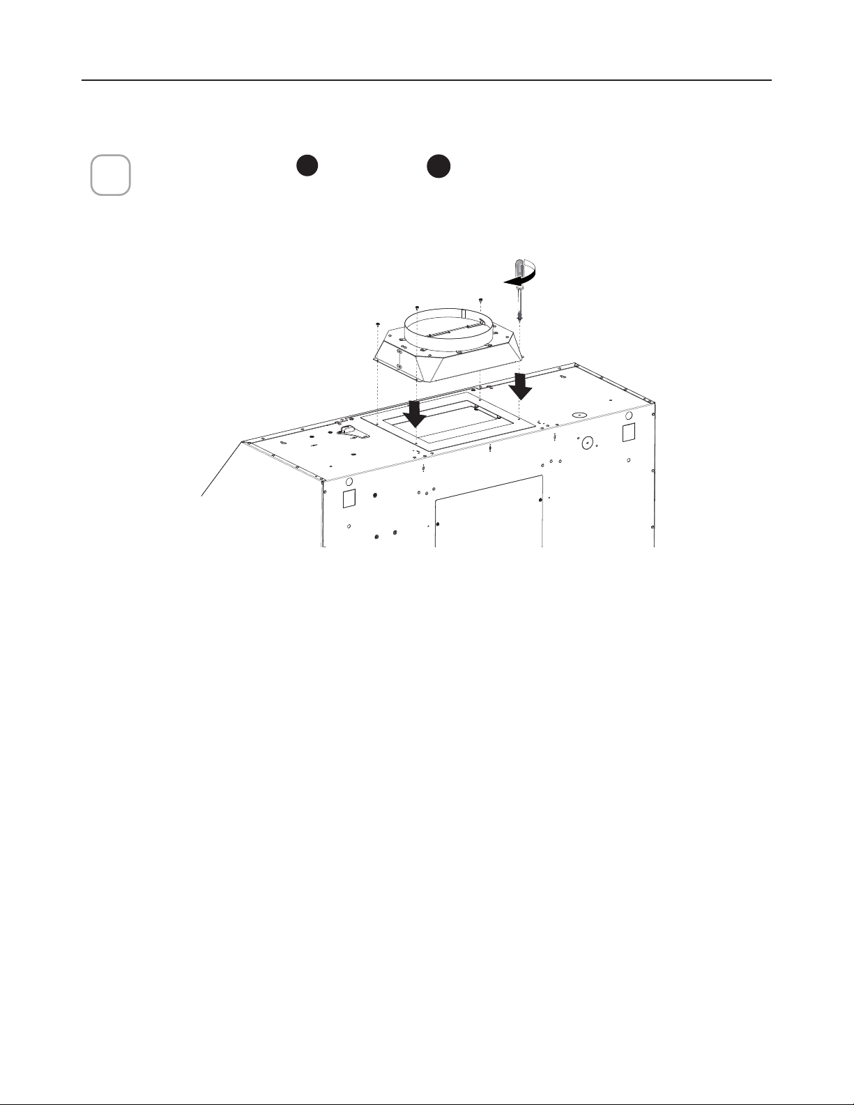
13
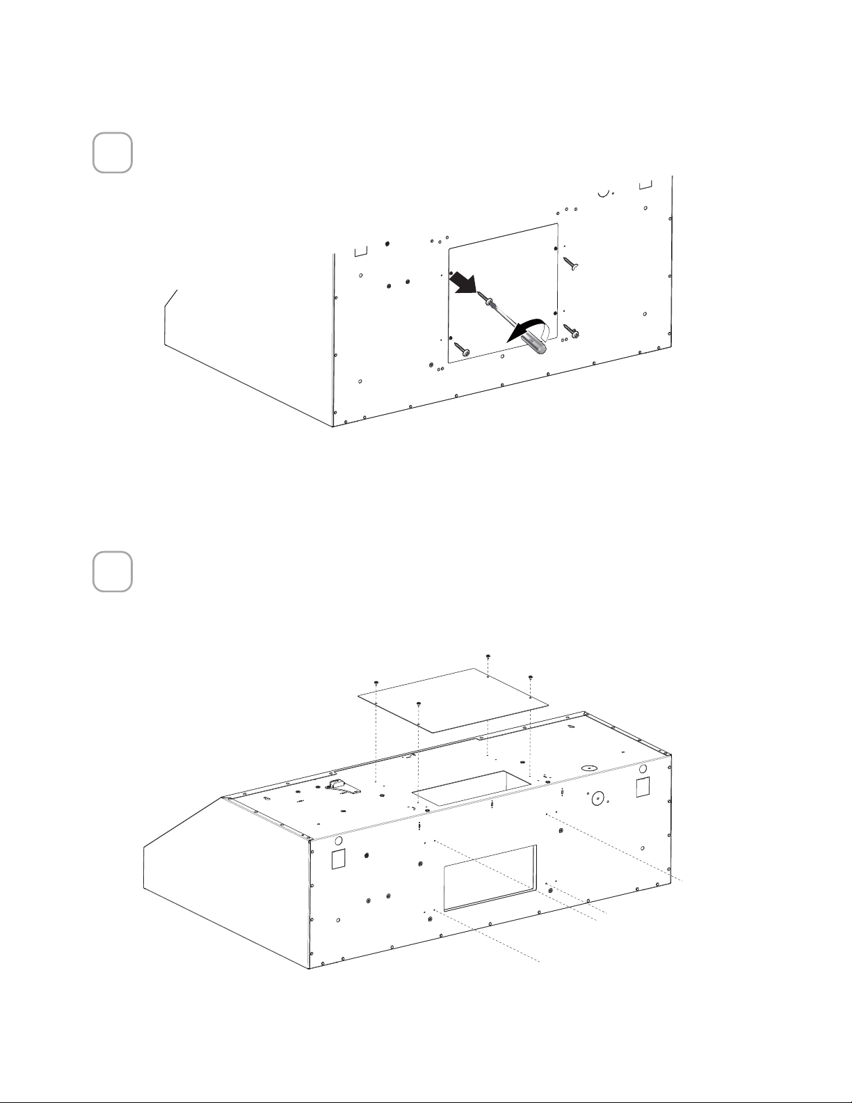
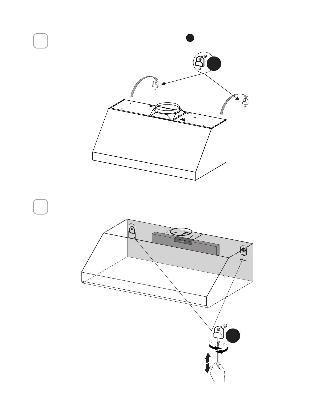
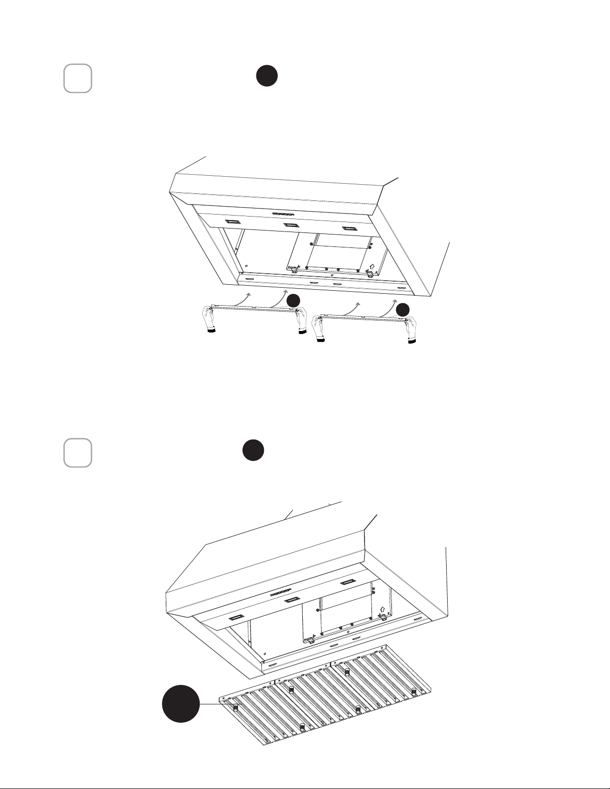
MOUNT THE DAMPER INTO THE HOOD
1
Attach the Damper
E
with 4 screws
G
.
Top position
14
1
2
Ducting to the back
Unscrew the 8 screws (4 on top, 4 on the back) and remove the two duct plates on
the top and back of the hood
Attach the plate removed previously on the top and now the open plate is on the
back.
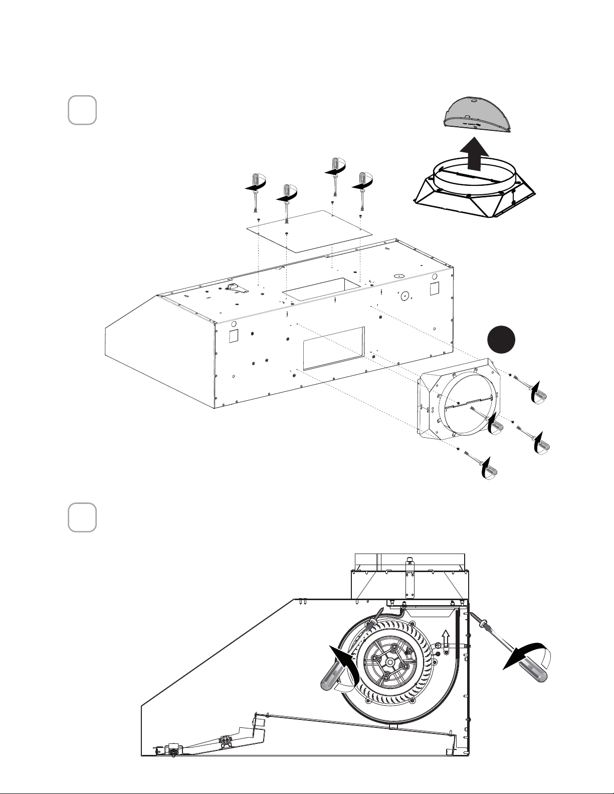
15
3
Remove the flaps from the damper and attach the
damper to the back of the hood with 4 screws. Attach
the closed metal plate to the top with 4 screws
E
4
Remove the 4 screws inside the hood on the Motor support and remove the
Motor.
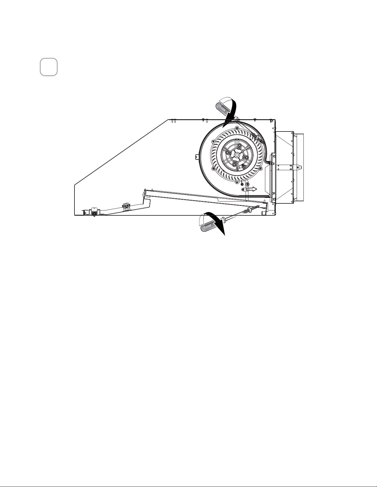
16
IMPORTANT - Attach the 4 previously removed screws to lock the motor in rear place.
5
17
1
2
Attach the spacer
F
with a screw
G
.
Attach the cap
M
.
MOUNT THE SPACER (ONLY FOR BREVA 30)
G
F
M
18
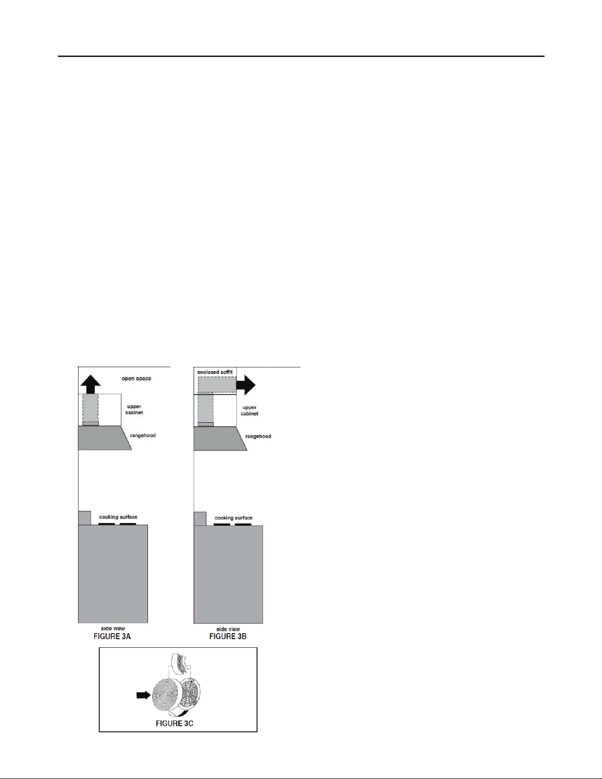
RECIRCULATION INSTRUCTIONS
For recirculating installations, Charcoal Filters are necessary. Remove all grease
filters and set aside. Attach one charcoal filter to each end of the Motor. Each
charcoal filter attaches to the grid on the side of the Motor. Rotate the filter
clockwise to install and counterclockwise to remove (FIGURE 3C). Replace all
grease filters.
There are 2 ways to recirculate the hood:
1) Use the Ductless Recirculating Kit (sold separately), refer to installation in-
structions inside the Recirculating Kit which includes charcoal filters.
#
DUCTGRT364
2) Duct work must be installed to exhaust the rangehood back into the kitchen,
either at the top of the cabinet (FIGURE 3A) or at the face or side of the soffit
(FIGURE 3B). Install at least 15" of metal duct (fig.3A and 3B) at the air exit. Run
the duct vertically and secure it at the opening cut out at the top or side of the
cabinet or soffit. Installation of metal grill is recommended. This duct work must
not terminate into a dead air space. #
FILTER6 must be purchased to complete
this type of installation.
Note: It is recommended that
professional style cooking always
be vented to the outside; for
recirculating Installations, some
duct work is required to exhaust
the unit out of the cabinet.
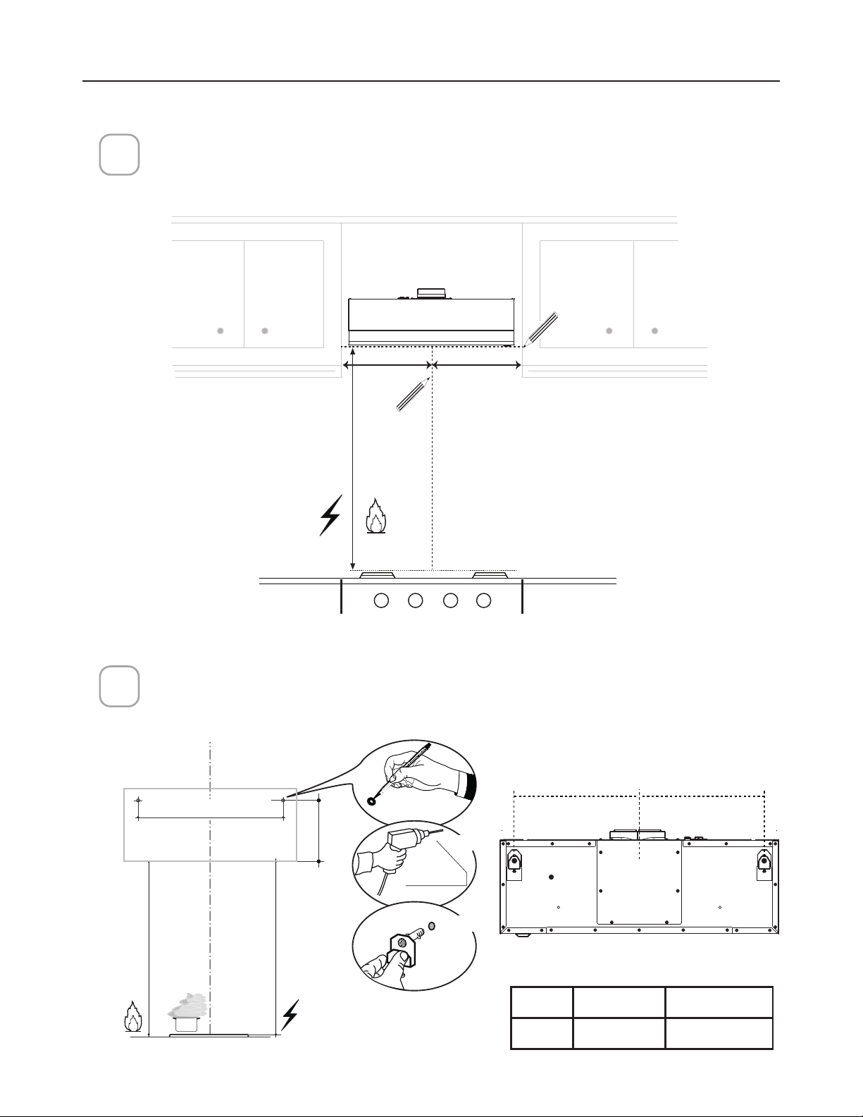
19
Draw a vertical line on the supporting wall as high as practical, at the center of the area
in which the hood will be installed.
Draw a horizontal line at where the bottom edge of the hood will be located as indicated
in the figure that is a minimum of 24"- 30" above cooking surface
Mark the wall where indicated at 17 7/16" above the horizontal line at the bottom of
the hood. Measure and mark the distance L from the left and right of the vertical line
as indicated.
==
Min.24" Min.30"
´
[
[
´
´
//
´
MOUNTING ON THE WALL
1
2
´
Breva 30 Breva 36
L
8" 14 15/16"
20
3
4
E
E
Hang the hood body onto the wall brackets
N
.
Use a level to insure the hood is even on the wall, use a screwdriver to adjust
the brackets as shown. Fully tighten the bracket once level.
N
N
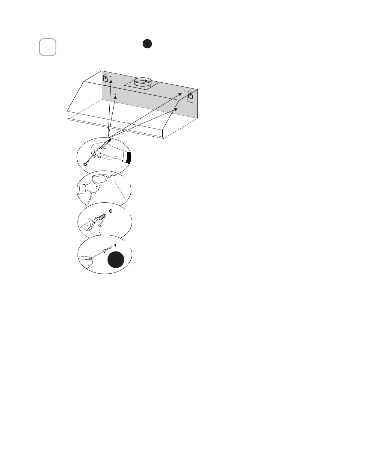
21
5
´
[
[
[
Mark the wall where indicated.
Drill directly into ø 5/16" holes at all the center points
marked.
Insert the purchased Wall brackets in the holes.
Using the remaining screws to anchor the hood in
the holes.
Attach 4 safety screws
L
to the back of hood into the wall. Follow the steps
indicated below to finish..
L
22
6
Attach the two grease rails
B
.
8
B
7
Attach the grease filters
C
by inserting the front of the filter into the hood
and pushing forward. Insert the back of the filter into the grease rail.
C
8
B
23
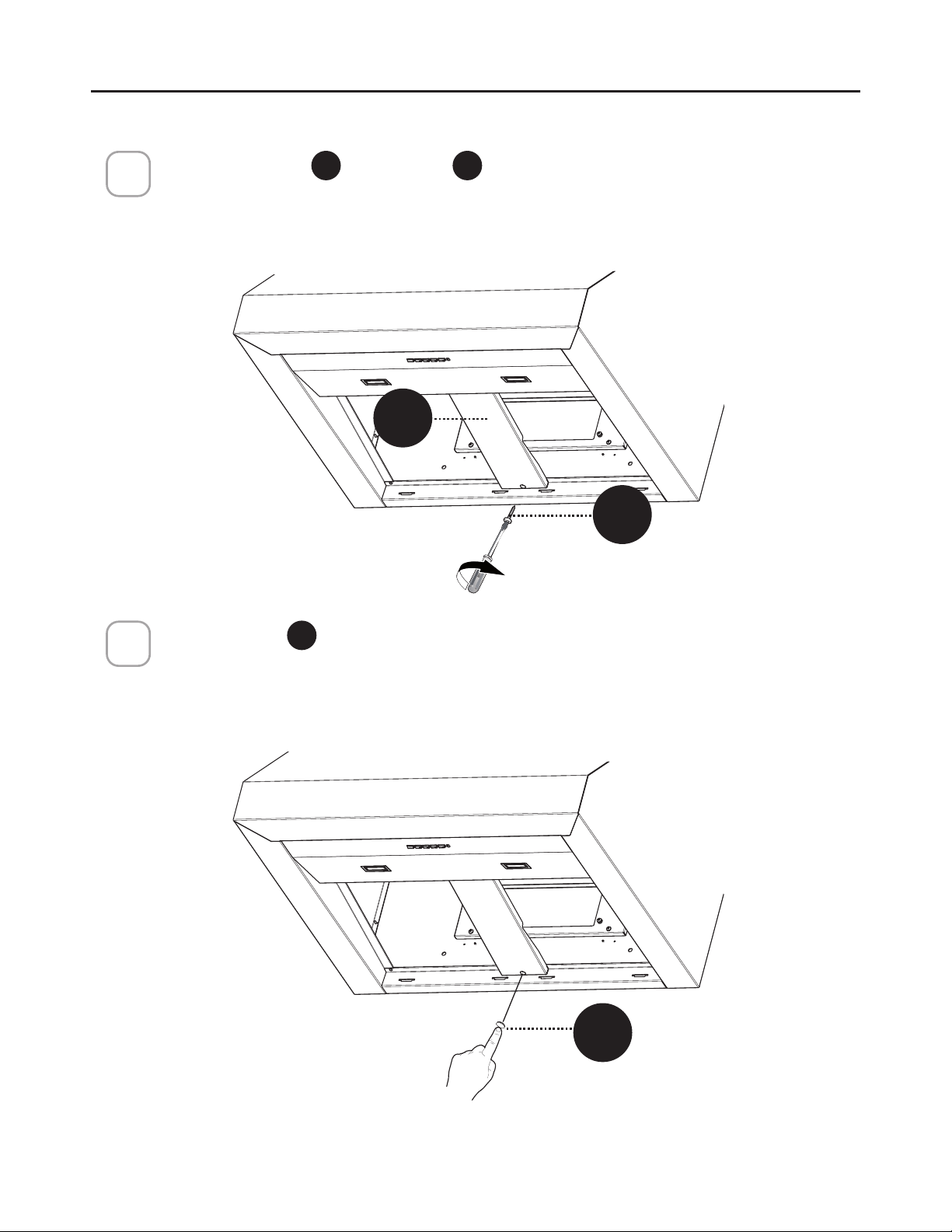
INSTALLATION FOR MOUNTING UNDER THE CABINET
SKIP THIS STEP IF USING WALL MOUNTING METHOD
IMPORTANT: Soffit or cabinet framing must be capable of supporting 100 lbs.
for 30" and 36" models and 150 lbs. for 48" models.
When necessary the hood may be installed so that it is supported by the sof-
fit or cabinet.
• The soffit should be constructed with 2"x4"’s.
• Use a level to draw the cooktop or range center line.
• Continue the centerline forward on the bottom of the soffit.
• Install horizontal wood supports between the 2”x4”.
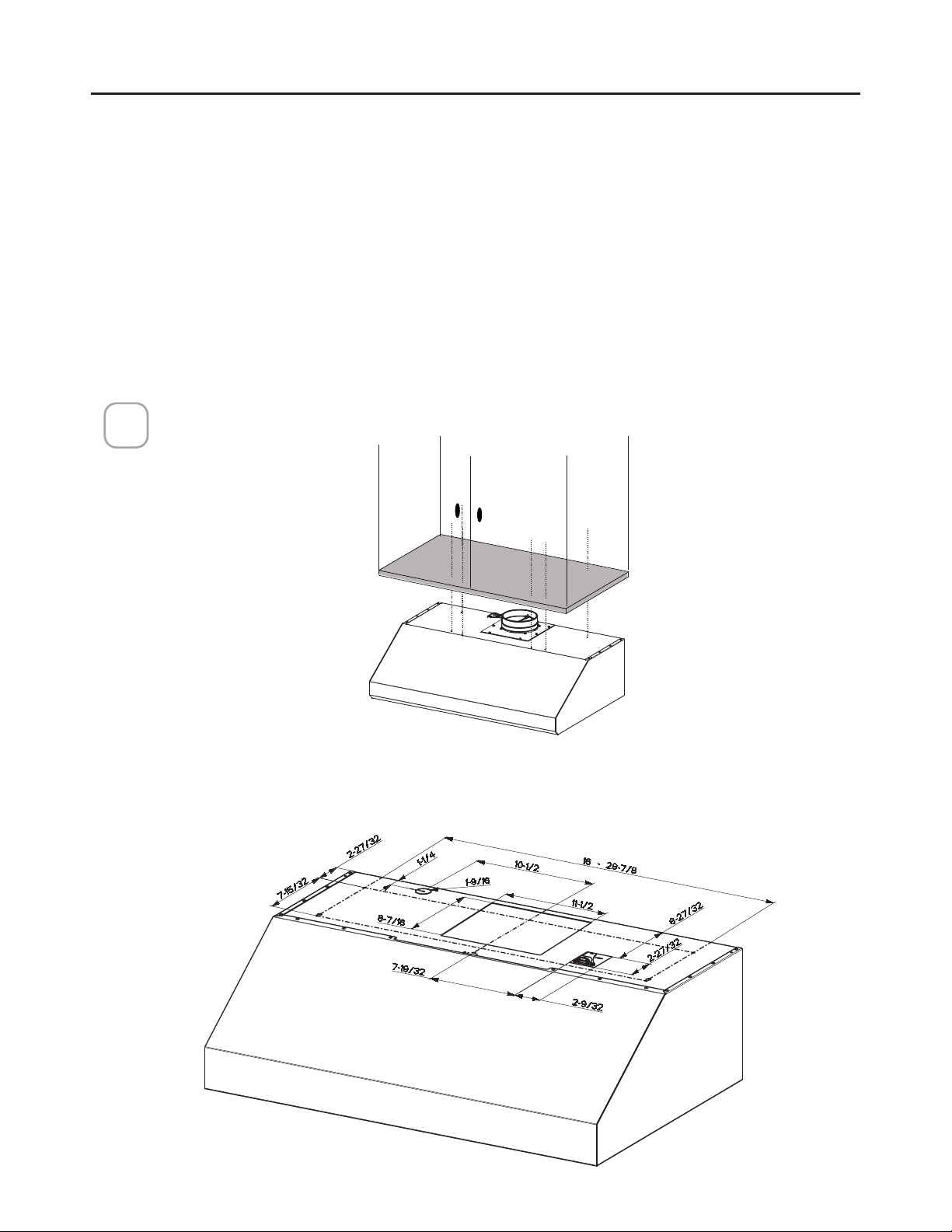
TOP DIMENSION
1
Lift the hood to the cabinet.
24
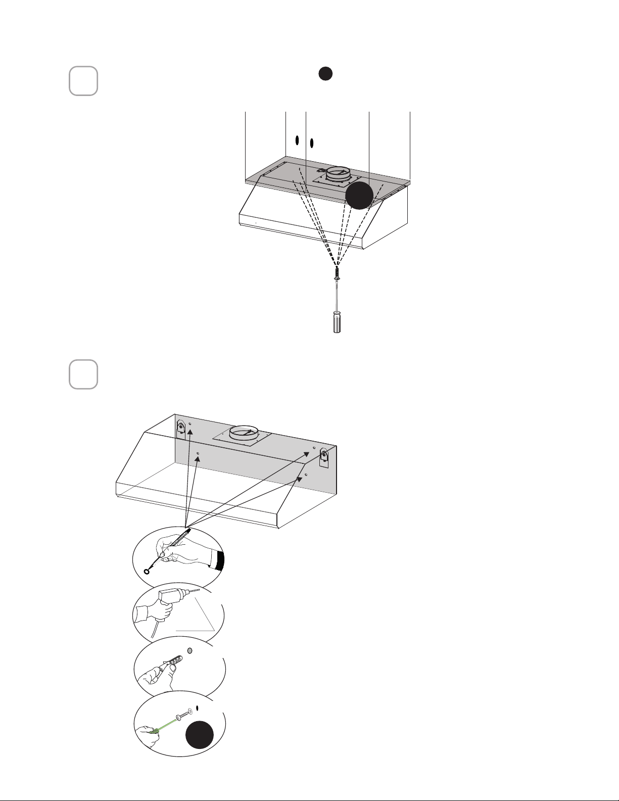
2
Attach the Hood Body with 4 screws
I
from the bottom.
[
I
3
´
[
[
[
Mark the wall where indicated.
Drill directly into ø 5/16" holes at all the center points
marked.
Insert the purchased Wall brackets in the holes.
Using the four screws to anchor the hood in the
holes.
Secure the hood with 4 safety screws on the back wall.
L
25
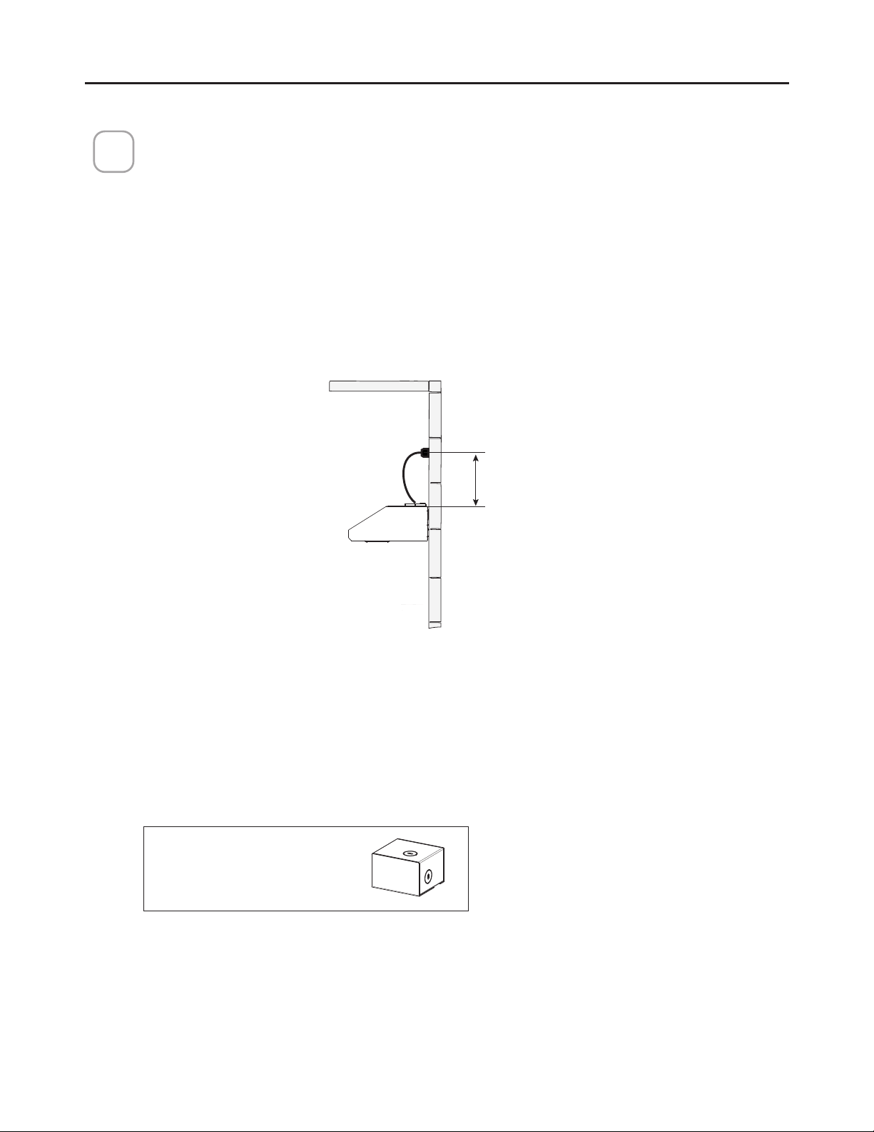
The power cord shall be accessible for inspection after installation.
ELECTRICAL INSTALLATION WITH OPTIONAL WIRING BOX
For permanent wiring, use only the Direct Connect Wiring Box accessory sku
WIREBOX2, manufactured by Faber.
ELECTRICAL INSTALLATION WITH CONNECTION CABLE
GROUNDING INSTRUCTIONS This appliance must be grounded. In the event
of an electrical short circuit, grounding reduces the risk of electric shock by
providing an escape wire for the electric current. This appliance is equipped
with a cord having a grounding wire with a grounding plug. The plug must be
plugged into an outlet that is properly installed and grounded.
WARNING - Improper grounding can result in a risk of electric shock.
Consult a qualified electrician if the grounding instructions are not completely
understood, or if doubt exists as to whether the appliance is properly grounded.
Do not use an extension cord. If the power supply cord is too short, have a
qualified electrician install an outlet near the appliance.
CONNECTING HOUSE POWER
8
Max. 33 7/16”
Direct Connect Wiring
Box Accessory sku
#WIREBOX2
(purchased separately)
26
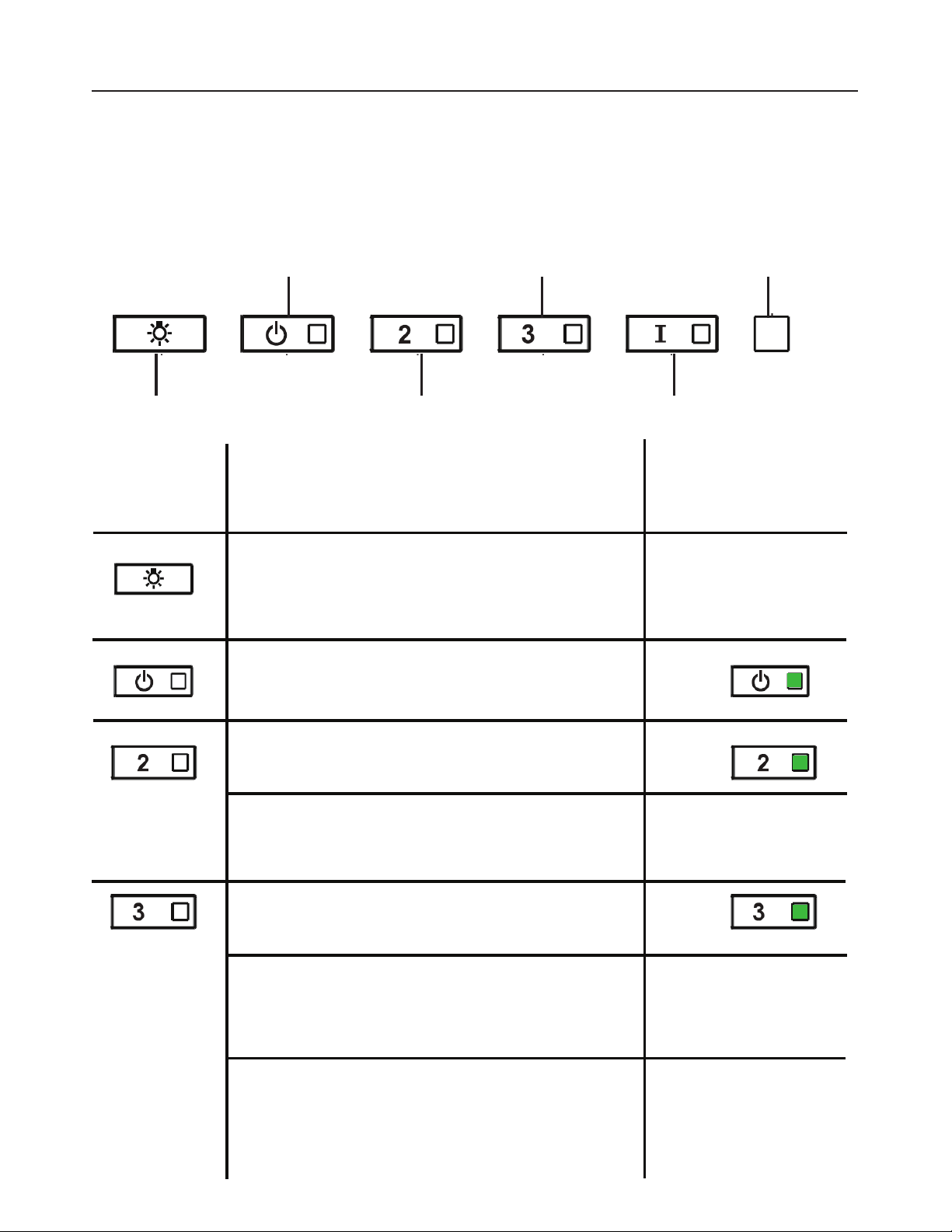
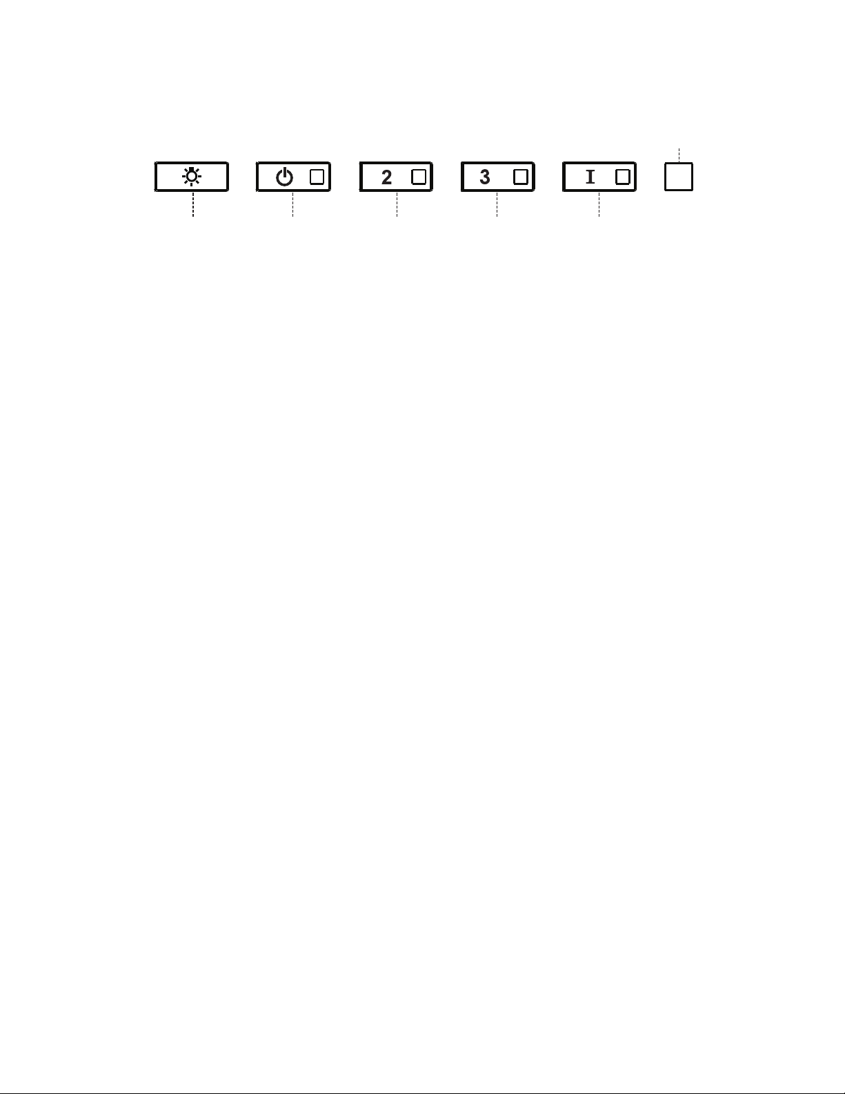
OPERATING THE CONTROLS
FOR BEST RESULTS
Start the Range Hood several minutes before cooking to develop proper
airflow. Allow the Range Hood to operate for several minutes after cooking
is complete to clear all smoke and odors from the kitchen.
A - LIGHTS
B - POWER
C - SPEED 2
D - SPEED 3
E - INTENSIVE
F - LED
A - LIGHTS - The lights have 3 levels - high,
medium, low, off - press the light button to
change the levels. With a 2 second press,
the lights will turn off.
BUTTON FUNCTION INDICATOR
B - POWER - A quick press turns the
motor on/off at speed one
C - SPEED 2 - A quick press turns the motor
on at speed two
All LED’s flash twice
(alarm activated). All
LED’s lit for 1 second
(alarm deactivated)
D - SPEED 3 - A quick press turns the
motor on at speed three
Activate / Deactivate the Delay function:
A Long press with the motor On and lights
Off: (The motor and lights will shut off
after 30 minutes)
Reset Grease Filter and / or Charcoal
Filter Alarm - A long press with the motor
and lights off to reset the filter wash
alarms
The current speed LED
flashes
All LED’s flash 3 times
Activate / Deactivate charcoal filter alarm -
A long press with the lights on and motor off
will activate or deactivate the charcoal alarm.
27
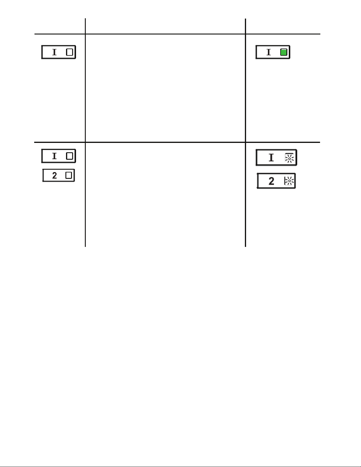
E - INTENSIVE LEVEL 1 - A quick press will
operate intensive speed level 1 for 6 minutes.
INTENSIVE LEVEL 2 - A 2 - second press will
operate intensive speed level 2 for 6 minutes.
At the end of the 6 minutes the hood returns
to the speed that was set before. If intensive
is set with the motor turned off, the hood will
turn off after 6 minutes.
BUTTON FUNCTION INDICATOR
Grease Filter Alarm - If the speed two and
intensive buttons are lit, this means the
Grease Filter saturation alarm is activated
and the grease filters should be washed. The
alarm turns on after 100 hours of operation.
Charcoal Filter Alarm - if the alarm is
activated, the speed two and intensive lights
will blink. This means the Charcoal filters
should be replaced AND the grease filters
should be washed. The charcoal filter alarm
turns on after 200 hours of operation.
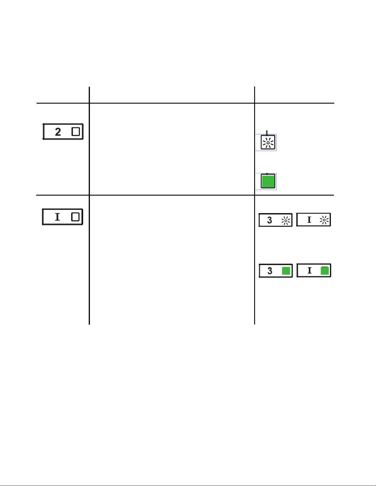
Heat Sensor Information - The hood is equipped with a
temperature sensor which, if the motor is off and the temperature
below the stove is high, activates the motor at maximum speed.
The condition is indicated by the blinking of Speed 1 and 2 LED’s
, Speed 3 LED is lit. This condition persists until the temperature
returns below the threshold. It is possible to exit this mode by
selecting one of the speeds.
28
BUTTON FUNCTION INDICATOR
WI-FI CONNECTIONS
Activate / Deactivate the Wi-Fi Connection
function.
A long Press of the speed 2 button with motor
and lights Off to activate / deactivate the WI-FI.
Note: the Wi-Fi function is automatically
activated when the user requests the Wi-Fi
configuration procedure.
Connection to
home wireless
router in
progress.
Wi-Fi connection
activated.
Starting the Wi-fi setup
A long press with the motor and lights Off
to Enter or End the Wi-Fi set-up procedure.
Before starting the procedure use the Faber
Cloud App to register with the IOT Faber
system. Then follow the instructions to add a
new device and register your home wireless
router.
If the procedure is not successfully completed
within a few minutes, stop the set up process
by holding the intensive button for 3 seconds.
Hold the button again for 3 seconds to start
the process. The hood will stop the Wi-fi set up
process if not successfully completed within 15
minutes.
Set Up is in
progress
F - LED
When setup is
finished LED’s
stay lit for 2
seconds.
This device complies with part 15 of the FCC Rules. Operation is subject
to the following two conditions: (1) This device may not cause harmful
interference, and (2) this device must accept any interference received,
including interference that may cause undesired Operation.
29
CFM ADJUSTMENT < 295CFM
To start the process make sure the hood lights are On and motor is Off.
S1
L T1 T2 T3 T4
1) Press and hold T1 for 7 seconds until all LED's flash.
2) After flashing has stopped, press T1.
3) T1 button will flash once, then press T1 button again to confirm your
choice (pressed within 10 seconds)
4) The four LED's will flash again to confirm you have finished the CFM
adjustment to less than 295 CFM.
5) Apply the under 295 CFM label inside the hood (behind the grease
filters) near the rating label for inspection and on the front of your
installation/user manual.
6) To confirm your setting for inspection, T1 and T2 buttons will always
operate the hood at the same speed. The highest speed(T3) and the
intensive speed (T4), will also no longer operate.
Note: T2 and T3 buttons will now operate at the same level and the
Intensive Speed will be deactivated.
Attention: When the under 295 CFM adjustment is completed, it is no
longer possible to change this setting to the original CFM level.
ATTENTION: For a correct functioning of the FABER CLOUD APP, when
this procedure is completed disconnect the plug from the power supply
and reconnect it again.

30
CFM ADJUSTMENT < 395CFM
To start the process make sure the hood lights are On and motor is Off.
S1
L T1 T2 T3 T4
1) Press and hold T1 for 7 seconds until all LED's flash.
2) After flashing has stopped, press T2
3) T2 button will flash once, then press T2 button again to confirm your
choice (pressed within 10 seconds)
4) The four LED's will flash again to confirm you have finished the CFM
adjustment to less than 395 CFM.
5) Apply the under 395 CFM label inside the hood (behind the grease
filters) near the rating label for inspection and on the front of your
installation/user manual.
6) To confirm your setting for inspection, the intensive speed function, will
no longer operate.
Note: T3 and T4 buttons will now operate at the same level and the
Intensive Speed will be deactivated.
Attention: When the under 395 CFM adjustment is completed, it is no
longer possible to change this setting to the original CFM level.
ATTENTION: For a correct functioning of the FABER CLOUD APP, when
this procedure is completed disconnect the plug from the power supply
and reconnect it again.
31
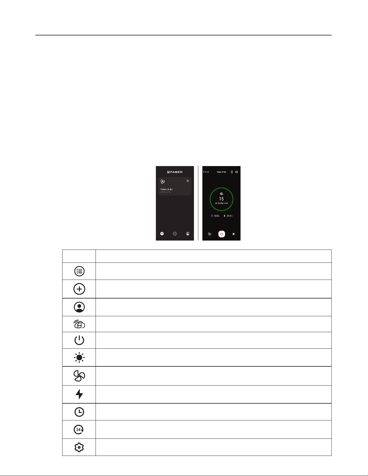
FABER CLOUD APP
Faber Cloud App
Your range hood is compatible with the Faber Cloud app. All you need is a
Internet connected Wi-Fi network that is within range of the range hood.
You can control all the functions of your range hood from anywhere using a
mobile device or your Amazon Alexa or Google Home smart speaker. When
connected to your smart speaker, you can control your hood with your voice.
The Faber Cloud app is available on iOS devices using iOS 11.0 or later or
Android devices using Android version 8 or later. Visit the Apple App Store
or Google Play Store for more information. Your range hood will have full
functionality if you are not using the Wi-fi or the Faber CLoud App features,
neither are required.
Please review the included Quick Connect Start Guide for more information.
Icon Function
Home page
Add new device
User profile management
Connected to Faber Wi-Fi network
Hood on/off
Lighting system management
Motor speed management
Intensive Function
Delay Function
24H function
App settings management
32
Cleaning Exterior surfaces:
Please note, abrasives and scouring agents can scratch range hood
finishes and should not be used to clean finished surfaces.
Stainless Steel finish cleaning instructions:
Clean exterior surfaces with a commercially available stainless steel
cleaner.
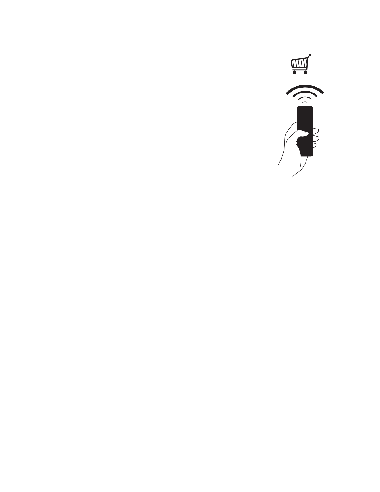
The remote control replicates the functions of the
control panel the hood. #
REMCTRL2
CLEANING STAINLESS STEEL
REMOTE CONTROL(Optional)
33
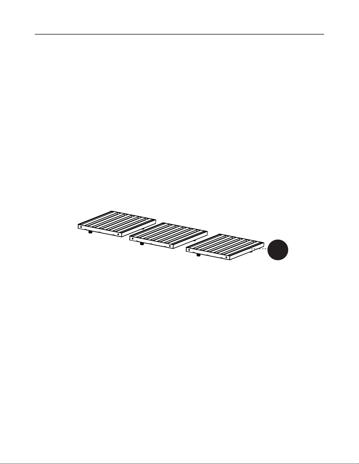
CARING FOR FILTERS
CLEANING METAL GREASE FILTERS
The metal grease filters can be cleaned in hot detergent solution or washed
in the dishwasher. They should be cleaned every 2 months use, or more fre-
quently if use is particularly heavy.
1. Remove the filter by pushing towards the back of the unit and at
the same time pulling downward.
2. Wash the filter without bending it, leave it to dry thoroughly before
replacing (if the surface of the filter changes color over time, this
will have absolutely no effect on its efficiency).
3. Replace, taking care to ensure that the handle faces forward.
4. Cleaning in dishwasher may dull the finish of the metal grease filter.
5. Completely dry the filters before installing back into the hood. No
water should be trapped in the filter before reinstalling.
C
34
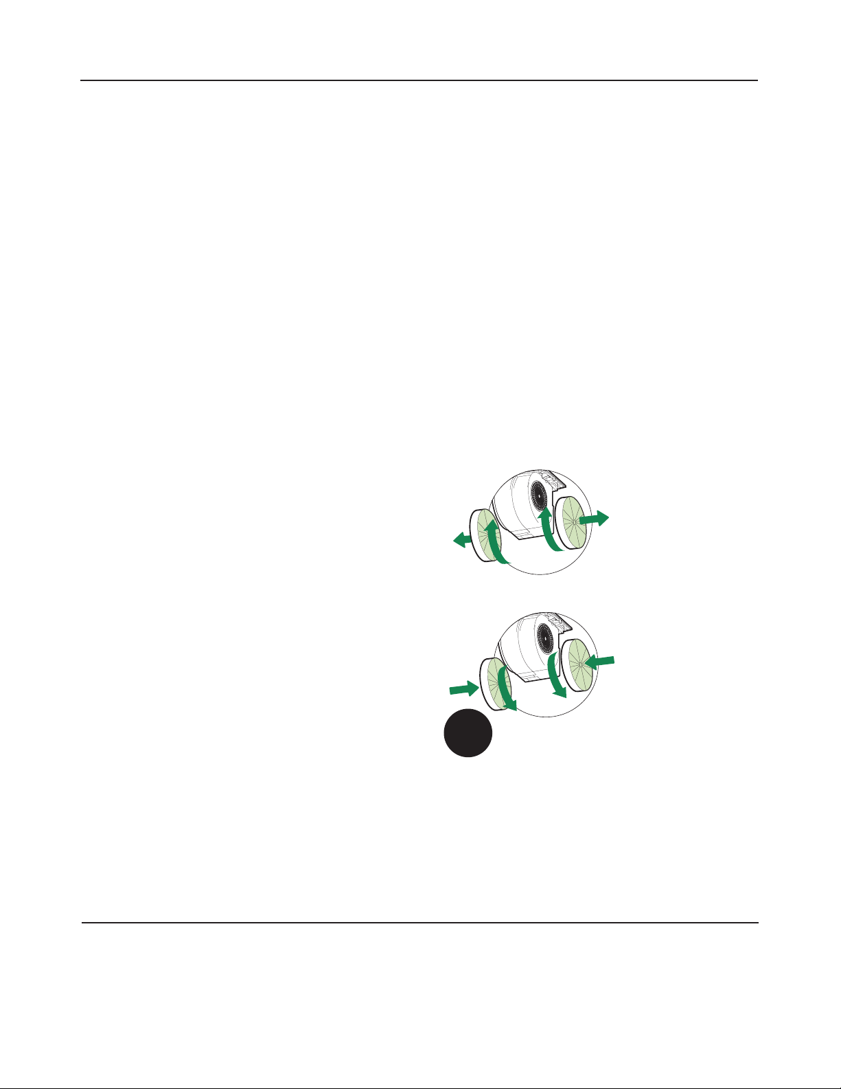
The Activated Charcoal Filters (# FILTER6) are not washable and cannot be
regenerated, and must be replaced approximately every 4 months of operation,
or more frequently with heavy usage.
1. Remove the Filter, pushing it towards the back of the unit and at the
same time pulling downward.
2. Remove the saturated Activated Charcoal Filters, as indicated (A).
3. Fit the new Filters, as indicated (B).
4. Replace, taking care to ensure that the handle faces forwards.
CAUTION: When used in recirculation mode, to Reduce the Risk of Fire
and Shock use only conversion kit Model #
FILTER6
A
B
W
REPLACING THE ACTIVATED CHARCOAL FILTER
REPLACING BULBS
LED lights must be replaced by Faber factory authorized service.
35
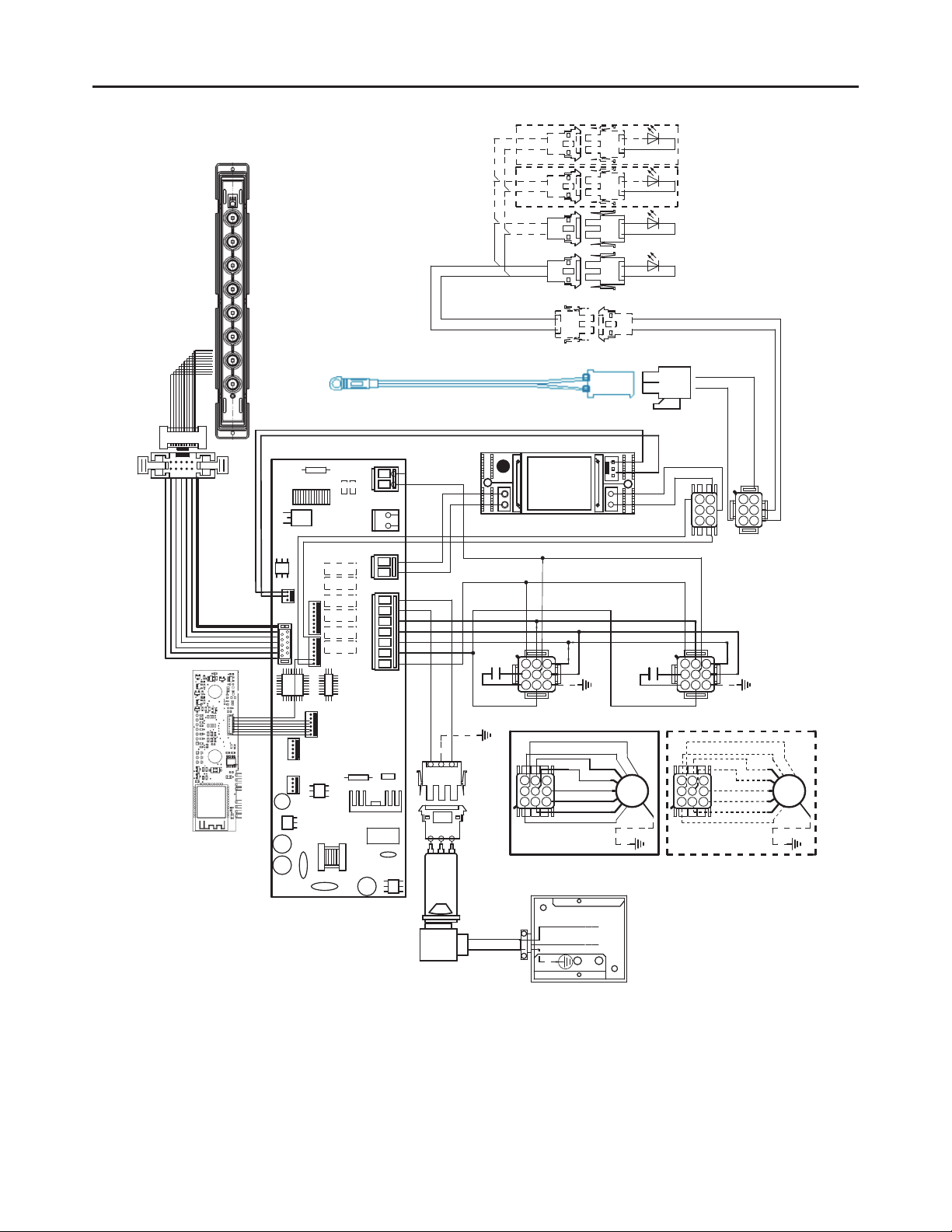
WIRING DIAGRAM
&UHDWLRQGDWH
)$%(5&RUUDGR
&UHDWHGE\
&RGH
09
/,1(
9DF+]
:,5,1*
%2;
6(&
(/(&7521,&
7516)250(5
/1
*5<
:+7
9/7
%5:
%5:
09
%/.
02725
*5<
25*
%/8
31.
:+7
)/$7&$%/(
%/.
/8;
$8;
)DEHU$7)
/8;
)/$7&$%/(
<*
:+7
*5<
%5:
5('
<(/
%/.
%/.
25*
*5<
*5<
*5<
%/.
%/.
%/.
*5<
"/('
%/.
*5<
%/.
*5<
%/.
*5<
5('
9/7
5('
25*
%/8
<*
%/.
25*
%/8
:+7
5('
<(/
*5<
%5:
25*

36
WARRANTY
Franke Home Solutions Warranty for Franke and Faber Branded Product
Effective March 1, 2022
In the United States, Canada and Latin America, Franke warrants the Faber branded products from manufacturing defects
in material and workmanship when purchased from a Franke or Faber Authorized Retailer pursuant to product-specific
warranties detailed herein (each, a “Warranty” and collectively, the “Warranties”). The products must be properly installed,
per Franke’s installation instructions, in their original installation, and used in normal indoor residential kitchen
applications. Any products or components which have been modified or altered from their original intended condition will
void the Warranty. The Franke Warranties for Faber branded products are limited to the original purchaser and are non-
transferrable. These Warranties do not include products purchased from non-Authorized Retailers, products that are
obsolete or discontinued, or products that were previous display models. All issues with installed products are considered
warranty claims and not subject to the Return Policy. Franke reserves the right to inspect any Franke / Faber product
reported to be defective pursuant to a Warranty claim and the original installation prior to providing a replacement product
and/or component. All decisions are final. In no situation shall the liability of Franke exceed the amount of the original
purchase price.
The Warranties do not cover, and Franke shall not be liable for, any damage to products or components resulting from
misuse or abuse, accidental damages, normal wear such as scuffs, scratches or finish reduction/fading, improper
installation, abnormal usage, negligence, damage caused by improper maintenance or cleaning. Damage caused by
impurities, corrosive chemicals or acts beyond Franke’s control are not covered by any Warranty. Service calls to correct
the installation of a range hood, instructions on how to operate a range hood, to replace or repair house fuses or to correct
house wiring or plumbing are not covered by any Warranty. Service calls to repair or replace range hood light bulbs, fuses
or filters and these consumable part costs are also excluded from Warranty coverage. Installation not in accordance with
electrical or plumbing codes or Franke / Faber documentation are not covered by any Warranty. Replacement parts or
repair labor costs for units operated outside the United States, Canada or Latin America, including any non-UL or C-UL or
non-NOM approved Franke / Faber range hoods are excluded from Warranty coverage. Expenses for travel and
transportation for service in remote locations and pickup and delivery charges are not covered by any Warranty. Franke /
Faber range hoods should always be serviced in the home in their original installation.
Franke / Faber product replacements do not include liability for project delays. Product replacements are not guaranteed
to be exact replacements. If the original product is not available at the time of the warranty claim, at Franke’s option, the
product replacements will be of similar size, material, and value. Any products or components which have been modified
or altered, from its original intended condition will void the warranty.
The Warranties do not allow recovery of incidental or consequential damages such as loss of use, delay, property
damage or other consequential damage, and Franke accepts no liability for such damages. Each Warranty is limited to
the conditions set forth herein and to the applicable warranty period specified herein and is exclusive. EXCEPT FOR THE
WARRANTIES SET FORTH HEREIN, FRANKE MAKES NO WARRANTY WHATSOEVER WITH RESPECT TO THE
PRODUCTS, INCLUDING, BUT NOT LIMITED TO, (1) ANY WARRANTY OF MERCHANTABILITY, (2) WARRANTY OF
FITNESS FOR A PARTICULAR PURPOSE, (3) WARRANTY OF TITLE, OR (4) WARRANTY AGAINST INFRINGEMENT
OF INTELLECTUAL PROPERTY RIGHTS OF A THIRD PARTY, WHETHER EXPRESS OR IMPLIED BY LAW, COURSE
OF DEALING, COURSE OF PERFORMANCE, USAGE OF TRADE OR OTHERWISE. LEGAL DISCLAIMER PLEASE
READ CAREFULLY. Franke Kitchen Systems LLC provides the above information to you as a public service to our
customers. By accessing and using this information, you agree to the following and to comply with all applicable laws. If
you do not agree with these terms and conditions, do not use this information. While we try to keep the information
current, changes may have occurred since its creation. Contact your Regional Manager or Customer Service to verify
information regarding Franke Kitchen Systems LLC programs and their use by you.
Franke / Faber Range Hood Limited Warranty:
Franke / Faber range hoods are warranted against any defect in materials or workmanship for the original purchaser for a
period of two (2) years from the date of original purchase when used in standard residential indoor applications. This
warranty covers labor and replacement parts. Franke, at its option, may repair or replace the product or components
necessary to restore the product to good working condition.

37
This warranty supersedes all other warranties, expressed or implied. No employee, field sales representatives, or
distribution persons are authorized to give any warranties on behalf of Franke Kitchen Systems, LLC
To make an installed product warranty claim please contact Franke at the provided contact information below. All warranty
claims must include the following for processing:
1. Proof of purchase from Franke or Faber Authorized Retailer
2. Original purchaser’s name, address (included city, state, zip), email address and phone number
3. Franke / Faber model and serial number
4. Date of installation
5. Description of the defect
6. Photos of the defect
In North America and Latin America:
Franke Home Solutions
Attn: Warranty Department
800 Aviation Parkway
Smyrna, TN 37167
Legal Entity:
Franke Kitchen Systems LLC

991.0636.908_02 - 210118
D00007291_01