
IMPORTANT MANUAL
Do Not Throw Away
Operator' s
Manual
Model No.
358.799240-32cc
CE
_k WARNING:
Read the Operator's Manual and
Follow All Warnings and Safety
Instructions. Failure To Do So
Can Result in Serious Injury.
Always Wear Eye Protection
qS/CRRF MnN,o
32cc GAS WEEDWACKER
2 Cycle Engine
o Assembly
• Operation
Fuel Mix 40:1
• Maintenance
• Repair Parts
Sears, Roebuck and Co., Hoffman Estates, IL 60179 UoS.A.
530-082597-04/19/94 © 1994, Sears, Roebuck and Co,
_,m _,,_,"u-_" _ _, _. ,_ _. _,- ._,x_- ,,- ._ _- ,_ ,_,_, ,,. _ _, _- .t,:,! ,,- _ _,, _,- ._ x_,,_- ._ ,x_, ,,_ ,, _-, _,- ,_ ,_,- _-- ,_ x_.,:,- ,_ _ _- ,, _, _:, ._ ,_- _. ,, _, _, ,, _- :,- ,, ,,_, _, ,_ ,x -¸ ;_- ,, y.
ONE YEAR LIMITED WARRANTY ON CRAFTSMAN GAS-POWERED WEEDWACKER ® TRIMMER
For one year from the date of purchase, when this Craftsman Gas- Powered Weedwacker is maintained, lubricated, and tuned
up accordingto the operating and maintenance instructions in the operator's manual, Seres will repair, free of charge, any defect
in materials or workraanehip_
This warranty excludes nylon line, spark plug, and air filter, which are expendable parts and become worn during normal use
If this Weedw_ckar is used for commarcial purposes, this warranty applies for only 90 days from the date of purchase If the
Weedwacker is used for rental pmlposes, this warranty applies for only 30 days from date of purchase. This warranty applies
only while this product is in use in the United States. WARRANTY SERVICE IS AVAILABLE BYRETURNING THE WEEDWACKER
TO THE NEAREST SEARS SERVICE CENTER IN THE UNITED STATES
This warranty gives you specific legal rlghtB, and you may also have other rights which vary from state to state
SEARS, ROEBUCK AND CO. DEPT. 817WA HOFFMANESTATES, IL 60179
TABLE OF CONTENTS
WARNINGS AND SAFETY INSTRUCTIONS •.. 3
KNOW YOUR UNIT ............................. 5
ASSEMBLY .................................. 6
ACCESSORIES ............................. 7
OPERATION (Fueling Your Engine) ............ 8
OPERATION (Stai'ting Your Engine) ....
USING YOUR TRIMMER ...............
CUSTOMER RESPONSIBILITY- -
GENERAL MAINTENANCE ........
.... • 9
.... 10
.... 14
REPAIR PARTS LIST ........................ 19
ENGINE TYPE:
DISPLACEMENT:
ENGINE RPM:
IGNITION:
IGNITION TIMING:
CARBURETOR'.
ENGINE "OFF":
STARTER:
MUFFLER:
CUTTING PATH:
FUEL TANK:
SPARK PLUG: .
SPARK PLUG GAP"
MODULE AIR GAP:
LUBRICATION:
CUTTING LINE:
2-Cycle, Air Cooled
32cc
Operating- - 7500
Idle- -3800-4400
Solid State
Spm'k Advance -
Non-adiustable
Diaphragm All Position With
Adiustable Fuel Mixture Jet
Positive Switch
Auto Rewind
Temperature Limiting
(not spark arresting)
16"
400cc
71-85854 (CJ-14)
.025"
.010" to .014"
Gasoline/Oil Mixture - 40:1
(see "Fueling Your Engine")
.080" Diameter Sears Line
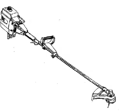
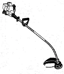
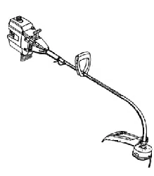
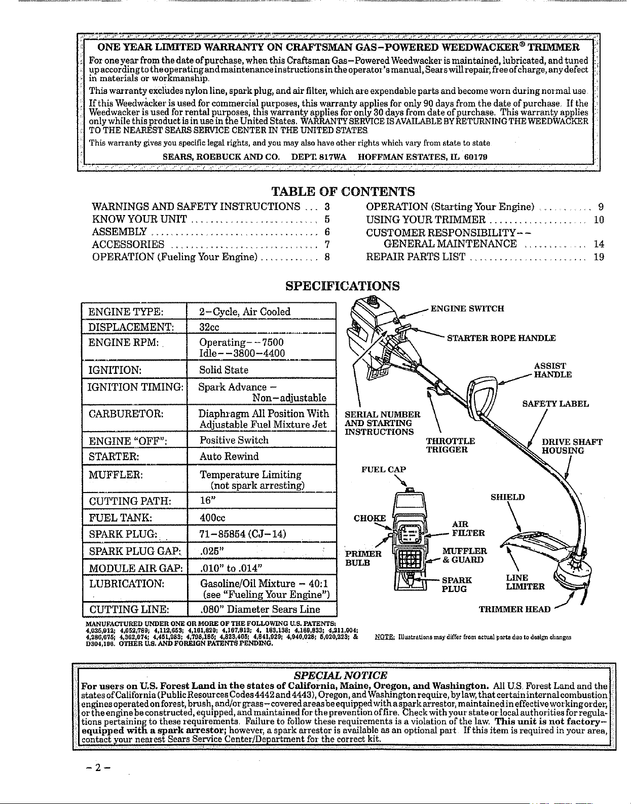
SPECIFICATIONS
_ ENGINE SWITCH
_ _ STARTER ROPE HANDLE
_ _ ASSIST
o
SERIAL NUMBER \ _ /
AND STARTING X _'_"'_ /
INSTRUCTIONS \ _ /
THROTTLE _ _ DRIVE SHAFT
TRIGGER "_"_OU SING
SHIELD kii '
CHOKE \
, /
SPAR] LINE _'_:
PLUG LIMITER
TRINfMER HEAD J
MANUFACTURED UNDER ONE OR MORE OF THE FOLLOWING U.S. PATENTS_
4,035,S12_ 4,052.789_ 4,11S.653; 4,1SI,820_ 4.167.812; 4. 183.138_ 4.189.833_ 4,21L004_
4,286,675_ 4,3t_2,074; 4_451,I}8S; 4,798,18_; 4,823,4(1_I 4,84LB29; 4,940,028_ _,020,223; & _ IUun_ration_ may differ from actual parte duo to design ¢hango_
D304,198. OTHER U,S, AND FOREIGN pATENTS PENDING.
SPECIAL NOTICE
For users on U.S. Forest Land in the states of California, Maine, Oregon, and Washington. All U.S Farest Land and the
states of California (Public Resources Codes 4442 and 4443), Oregon, and Washington require, by law, that certain internal combustion
engines operated on forest, brush, and]or grass - covered areas be equipped with a spark arrestor, maintained in effective working order_
or the engine be constructed, equipped, and maintained for the prevention of fire. Check with your'state or local authorities for regula-
tions pertaining to these requirements. Failure to follow these requirements is a violation of the law. Thin unit is not factory-
equipped with a spark arrestor; however, a spark arrestar is available as an optional paz t If this item is required in your area,
contact _our nearest Sears Service Center/Department for the correct kit.
--2--
WARNINGS AND SAFETY INSTRUCTIONS
(See Additional Safety Instructions throughout this Manual)
Ak WARNING - THIS POWER TOOL CAN BE DANGEROUS! This unit can cause serious
injury or blindness to the operator and others, The warnings and safety instructions in this manual must be fol-
lowed to provide reasonable safety and efficiency in using this unit The operator is responsible for following the
warnings and instructions in this manual and on the unit. Read the entire Operator's Manual before assem-
bling and using this unit! Restrict the use of this power tool to persons who read, understand and
follow the warnings and instructions in this manual and on the unit.
i
000
,A
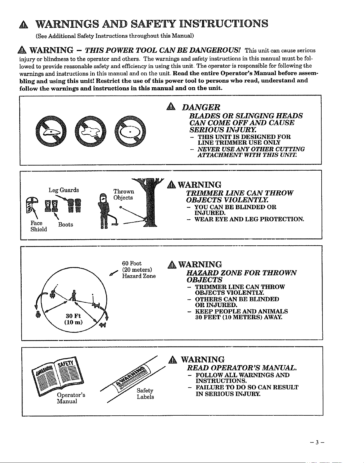
DANGER
BLADES OR SLINGING HEADS
CAN COME OFF AND CAUSE
SERIOUS INJURY.
- THIS UNIT IS DESIGNED FOR
LINE TRIMMER USE ONLY
- NEVER USE ANY OTHER CUTTING
ATTACHMENT WITH THIS UNIT.
Face
Shield
Leg Guards
!1
\
Boots
_k WARNING
TRIMMER LINE CAN THROW
OBJECTS VIOLENTLY.
- YOU CAN BE BLINDED OR
INJURED.
- WEAR EYE AND LEG PROTECTION.
60 Foot
(20 meters)
I" Hazard Zone
Ak WARNING
HAZARD ZONE FOR THROWN
OBJECTS
- TRIMMER LINE CAN THROW
OBJECTS VIOLENTLY.
- OTHERS CAN BE BLINDED
OR INJURED.
- KEEP PEOPLE AND ANIMALS
30 FEET (10 METERS) AWAY.
Operator's
Manual
Safety
Labels
WARNING
READ OPERATOR'S MANUAL.
- FOLLOW ALL WARNINGS AND
INSTRUCTIONS.
- FAILURE TO DO SO CAN RESULT
IN SERIOUS INJURY.
-3-
WARNINGS AND SAFETY INSTRUCTIONS....(Contlnued)
OPERATOR SAFETY
• Always wear safety eye protection.
• Always wear long pmlts, long sleeves, boots and
gloves. Wearing safety leg guards is recom-
mended. Do not go barefoot or wear sandals, jew-
elry, shoi_ pants, short sleeves, loose clothing, or
clothing with loosely hanging ties, straps, tassels,
etc.; they can be caught in moving parts.
• Secure hair so it is above shoulder length
• Do not operate this unit when you are tired, ill, or
under the influence of alcohol, drugs, or medica-
tiom
• Wear hearing protection if you use this unit for
more than 1- 1/2 hours per day.
• Never start or run the engine inside a closed room
or building. Breathing exhaust fumes can kill
• Keep handles free of oil and fuel.
UNIT/MAINTENANCE SAFETY
• Look for and replace damaged or loose parts be-
fore each use. Look for and repair fuel leaks before
use. Keep the unit in good working condition
Replace trimmer head parts that are chipped,
cracked, broken, or damage in any other way be-
fore using the unit.
Use only _080" diameter SEARS Line. Never use
wire, rope, string, etc.
• Make sure the unit is assembled correctly as listed
in this manual.
• Make carburetor adjustments with the lower end
supported to prevent the trimmer line from con-
tacting any object.
• Keep others away when making carburetor ad-
justments.
o Disconnect the spark plug before performing
maintenance except carburetor adjustments.
• Use only genuine SEARS accessories and replace-
ment parts as recommended for this unit.
A FUEL SAFETY
• Mix and pour fuel outdoors.
Keep away from sparks or flames.
• Use a container approved for fuel.
• Do not smoke or allow smoking near fuel or the
unit or while using the unit,
Wipe up all fuel spills before starting engine.
• Move at least 10 feet (3 meters) away from fueling
site before starting engine.
• Stop engine and allow the engine to cool before re-
moving fuel cap.
• Empty the fuel tank before storing the unit. Use
up fuel left in the carburetor by starting the en-
gine and letting the engine run until it stops.
° Store unit and fuel in an area where fuel vapors
cannot reach sparks or open flames from water
heaters, electric motors ar switches, furnaces, etc.
CUTTING SAFETY
• Inspect the area to be cut before each use_ Remove
objects (rocks, broken glass, nails, wh'e, string,
etc) which can be thrown or become entangled in
the trimmer head.
• Keep others including childl'en, animals, bystand-
ers and helpers outside the 60 foot (20 meter) Haz-
ard Zone. Stop the engine immediately if you are
approached.
° Always keep the engine on the right-hand side of
your body.
Hold the unit firmly with both hands.
° Keep firm footing and balance Do not over-
reach.
• Keep the trimmer head below waist level
• Do not raise the engine above your waisL
• Keep all parts of your body away from trimmer
head and muffler when engine is running_
• Cut from your right to your left,
• Use only for jobs explained in this manual_
TRANSPORTING AND STORAGE
• Stop the unit before transporting.
• Keep the muffler away from your body_
• Allow the engine to cool, and secure the unit be-
fore storing or transporting in a vehicle_
o Empty the fuel tank before storing or transport-
ing the unit. Use up fuel left in the carburetor by
starting the engine and letting it run until it stops.
° Store unit and fuel in an area where fuel vapors
cannot reach sparks or open flames from water
heaters, electric motars or switches, furnaces, etc.
o Store unit so line limiter cannot accidentally
cause injury. The unit carl be hung by the bracket
below the engine or by the tube_
• Store the unit out of the reach of children.
If situations occur which are not covered in this manual, use care and good judgment.
If you need assistance, contact your SEARS Service Center/Department or the
CUSTOMER ASSISTANCE HOTLINE, 1-800-235-5878.
S ET NOTIC
H Exposure to vibrations through prolongeduse of gasaline powered hand tools could cause blood vessel or nerve
M damage in the fingers, hands, and wrists of people prone to circulation disorders or abnormal swellings. Pro-
|!!| longed use in cold weather has been linked to blood vessel damage in otherwise healthy people. If symptoms
H occur such as numbness, pain, loss of strength, change m skin calor or texture, or loss.of feeling in the fingers,
|_| handsorwrlsts, discontinuetheuseofthlstoalandseekmedicalattention. Anantl-wbratlonsystemdoesnot
_!] guarantee the avmdance of these problems. Users who operate power tools on a continual and regular basis
F_ m_t m0nitor €!0sely their physicS, c0ndition and the c0ndit!°n 0f thin t0ol. .......
-4-
KNOW YOUR UNIT
A. INTRODUCTION
Your Trimmer is aversatile product developed for
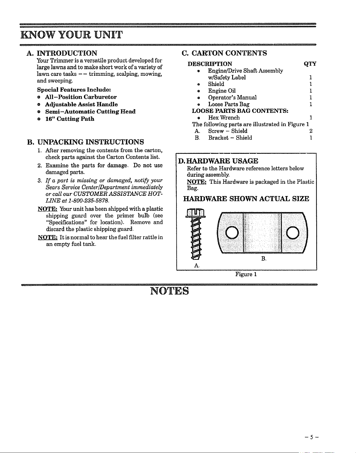
large lawns and to make short work of a variety of DESCRIPTION QTY
lawn care tasks - - trimming, scalping, mowing, e Engine/Drive Shaft Assembly
and sweeping+ w/Safety Label 1
e Shield 1
Special Features Include: e Engine Oil 1
® All-Position Carburetor o Operator's Manual 1
e Adjustable Assist Handle . Loose Parts Bag 1
e Semi-Automatic Cutting Head LOOSE PARTS BAG CONTENTS:
e 16" Cutting Path • Hex Wrench 1
The following parts are illustrated in Figure 1
A. Screw - Shield 2
B+ Bracket - Shield 1
B. UNPACKING INSTRUCTIONS
1, After removing the contents from the carton,
check parts against the Carton Contents lisL
2_ Examine the parts for damage. Do not use
damaged parts,
3. If a part is missing or damaged, notify your
Sears Service Center/Department immediately
or call our CUSTOMER ASSISTANCE HOT-
LINE at 1-800-235-5878+
NOTE.' Your unit has been shipped with a plastic
shipping guard over the primer bulb (see
"Specifications" for location), Remove and
discard the plastic shipping guard,
N___O_T_AIt is normal to hear the fuel filter rattle in
an empty fuel tank+
C. CARTON CONTENTS
D. HARDWARE USAGE
Refer to the Hardware reference letters below
during assembly.
This Hardware is packaged in the Plastic
Bag.
HARDWARE SHOWN ACTUAL SIZE
A,
iiiili?iiYI?ifi!!fii!!!!+i
B,
Figure 1
NOTES
ASSEMBLY
(If tool is received assembled, repeat all steps in this section to be sure assembly is correct and is ad-
justed for the operator.)
A. PREPARATION
This Operator's Manual is designed to help you as-
semble the tool and to provide its safe operation. It is
important thatTou read the entire manual to become
familiar with the tool before you begin assembly or
call our CUSTOMER ASSISTANCE HOTLINE at
1-800-235-5878.
1, Read your Operator's Manual
2. Tools you will need:
- Adjustable Wrench
- Standard Screwdriver
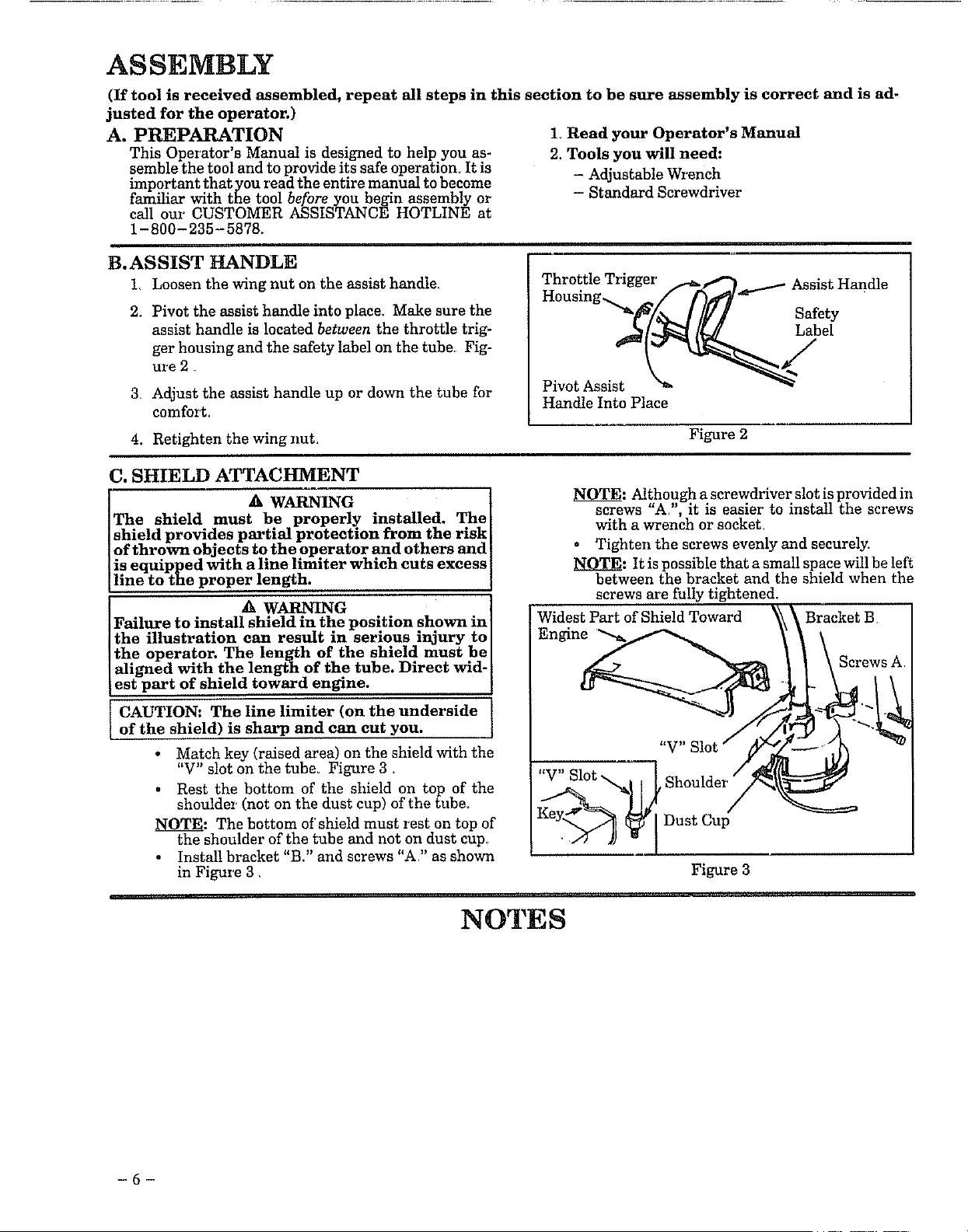
B.ASSIST HANDLE
L Loosen the wing nut on the assist handle,
2.
Pivot the assist handle into place. Make sure the
assist handle is located between the throttle trig-
ger housing and the safety label on the tube Fig-
ure 2
3 Adjust the assist handle up or down the tube for
comfort.
Throttle Trigger
Pivot Assist
Handle Into Place
_andle
Safety
Label
4. Retighten the wing nut. Figure 2
C. SHIELD ATTACHMENT
The shmld must be properly installed. The I
shield provides partial protection from the riskl
of thrown objects to the operator and others and
is equipped with a hne limiter which cuts excess]
line to the proper length. J
A WARNING
Failure to install shield in the position shown in
the illustration can result in serious injury to
the operator. The length of the shmld must be
aligned with the length of the tube. Direct wid-
est part of shield toward engine.
CAUTION: The line limiter (on the underside
of the shield) is sharp and can cut you.
• Match key (raised area) on the shield with the
"V" slot on the tube. Figure 3.
Rest the bottom of the shield on top of the
shoulder (not on the dust cup) of the tube.
_LO_T_: The bottom of shield must rest on top of
the shoulder of the tube and not on dust cup.
• Install bracket "B." and screws "A?' as shown
in Figure 3 •
NOTE: Although a screwdriver slot is provided in
screws "A/', it is easier to install the screws
with a wrench or socket_
• Tighten the screws evenly and securely.
_LO_T_: It is possible that a small space will be left
between the bracket and the shield when the
screws are fully tightened.
Wi:_s:PartofShieldToward _ _Braekst B
II SerewsA
"V" Slot _/"
Figure 3
NOTES
-6-
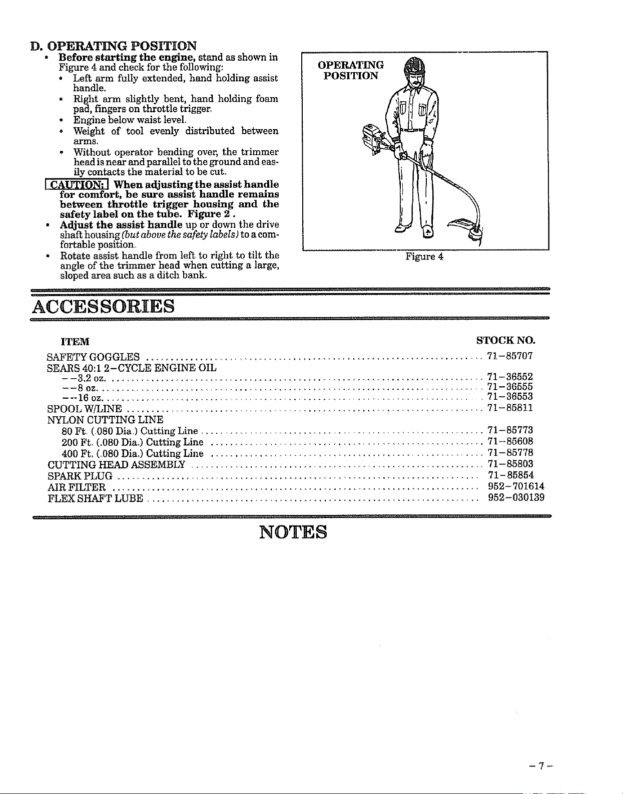
D. OPERATING POSITION
• Before starting the engine, stand as shown in
Figure 4 and check for the following:
• Left arm fully extended, hand holding assist
handle.
Right arm slightly bent, hand holding foam
pad, fingers on throttle triggen
• Engine below waist level.
o Weight of tool evenly distributed between
arms.
• Without operator bending over, the trimmer
head is near and parallel to the ground and eas-
ily contacts the material to be cut.
[ CAUTION: I When adjusting the assist handle
for comfort, be sure assist handle remains
between throttle trigger housing and the
safety label on the tube. Figure 2.
• Adjust the assist handle up or down the drive
shaft housing (but above the safety labels) to a com-
fortable position
, Rotate assist handle from left to right to tilt the
angle of the trimmer head when cutting a large,
sloped area such as a ditch bank.
OPERATING
POSITION
Figure 4
ACCESSORIES
ITEM STOCK NO.
SAFETY GOGGLES ...................................................................... 71-85707
SEARS 40:1 2-CYCLE ENGINE OIL
--3.2 oz ............................................................................... 71-36552
--8 oz................................................................................... 71-36555
- -16 oz................................................................................. 71-36553
SPOOL W/LINE ............................................................................ 71-85811
NYLON CUTTING LINE
80 Ft, (,080 Dia,) Cutting Line ........................................................... 71-85773
200 Ft, (.080 Dia.) Cutting Line ........................................................ 71-85608
400 Ft. (.080 Dia,) Cutting Line ......................................................... 71-85778
CUTTING HEAD ASSEMBLY ............................................................. 71-85803
SPARK PLUG ........................................................................... 71-85854
AIR FILTER ........................................................................... 952- 701614
FLEX SHAFT LUBE .................................................................... 952-030139
NOTES
-7-
OPERATION
BEFORE STARTING ENGINE: 2-CYCLE OIL:
WARNING
BE SURE TO READ THE FUEL SAFETY
INFORMATION IN THE WARNINGS
AND SAFETY INSTRUCTIONS SEC-
TION ON PAGE 4 OF THIS MANUAL
BEFORE YOU BEGIN.
IF YOU DO NOT UNDERSTAND THE
FUEL SAFETY SECTION DO NOT AT-
TEMPT TO FUEL YOUR UNIT;, SEEK
HELP FROM SOMEONE THAT DOES
UNDERSTAND THE FUEL SAFETY
SECTION OR CALL THE CUSTOMER
ASSISTANCE HOTLINE AT
1-800-235-5878.
GASOLINE
The two-cycle engine on this product requires a fuel mix-
ture of regular unleaded gasoline and a high quality en-
gine off for lubrication of the bearings and other moving
parts. The correct fue!!oil mixtureis 40:1 (see FuelMix-
furs Chart). Too little oil or the incon'ect oil type _ll
cause poor performance and may cause the engine to over-
heat and seize.
Gasoline and oil must be premixed in a clean approved fuel
container. Always use fresh regular unleaded gasoline.
IMPORTANt. Experience indicates that alcohol
blended fuels called gasohol (or using ethanol or metha-
nol) can attract moisture, which leads to oil]gas separa-
tion and formation of acids during storage. Acidic gas can
damage the fuel system of an engine while in storage. To
avoid engine problems, the fuel system should be emptied
before storage for 30 days or longer° Drain the gas tank,
then run the fuel out of the carburetor and fuel lines by
starting the engine and letting it run until it stops. Use
fresh fuel next season. See STORAGE instructions for
additional information. Never use engine or carburetor
cleaner products in the fuel tank or permanent damage
may occur.
FUEL STABILIZER
Fuel stabilizer is an acceptable alternative in minimizing
the formation of fuel gum deposits during storage. Add
stabRizer to gasoline in fuel tank or storage container.
Always follow the fuel mix ratio found on the stabilizer
container. Run engine at least 10 minutes after adding
stabilizer to allow the stabilizer to reach the carburetor.
You do not have to drain the fuel tank for storage ifyan are
using fuel stabilizer.
CRAFTSMAN 40:1 2 cycle engine oil is speciany blended
with fuel stabi_ers. If you do not use this Sears off, you
can add a fuel stabilizer (such as Craftsman No. 33500) to
your fuel tank.
CRAFTSMAN 40:1 2 cycle off is strongly recommended.
This oil is specially blended with fuel stabilizers for
increased fuel stability (extends fuel life up to 5 times
longer) and reduced smoke.
If CRAFTSMAN 2 cycle oil is not available, use a good
quality 2 cycle AIR-COOLED engine oil that has a
recommended fuel mix ratio of 40:l.
IMPORTANTI Do not use:
• AUTOMOTIVE OIL
• BOAT OILS (NMMA, BIA. etc.)
These oils do not have proper additives for 2-cycle,
AIR-COOLED engines and can cause engine damage.
GASOLINE AND OIL MIXTURE
Mix gasoline and oil as follows:
° Consult chart for correct quantities.
• Do not mix gasoline and oil directly in the fuel tank.
FOR ONE GALLON:
• Pour 3.2 ounces of high quality, 2-cycle engine oil
into an empty, approved one gallon gasoline con-
tainer.
• Add one gallon of regular unleaded gasoline to the
gallon container, then securely replace the cap_
Shake the container momentarily.
• The mixture is now ready for use. Fuel stabilizer
can be added at this time if desired; follow mixing
instructions on the label,
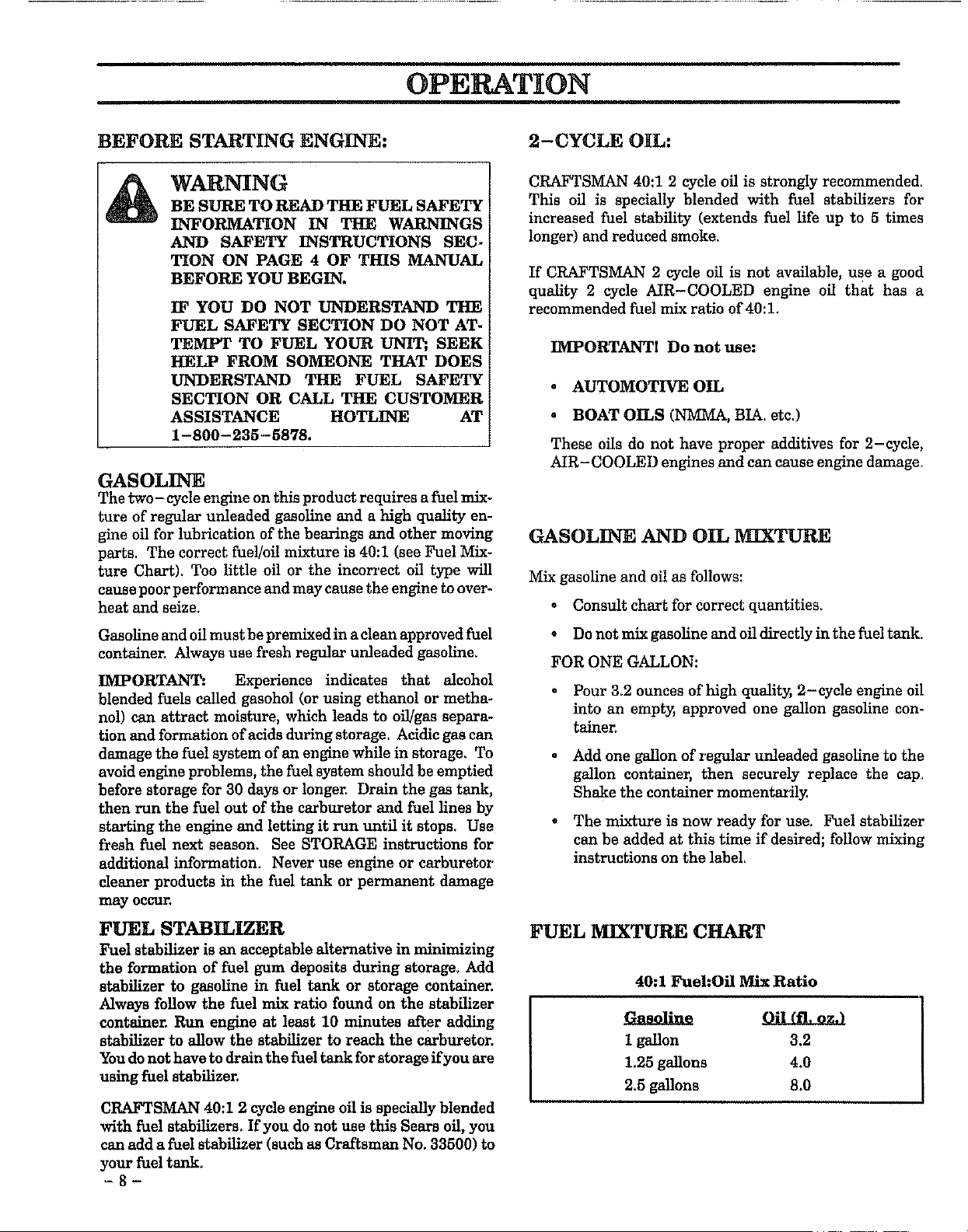
FUEL MIXTURE CHART
40:1 Fuel:Oil Mix Ratio
1 gallon 3.2
1.25 gallons 4.0
2.5 gallons 8.0
OPERATION
BEFORE STARTING ENGINE:
WARNING
BE SURE TO READ THE FUEL SAFETY
INFORMATION IN THE WARNINGS
AND SAFETY INSTRUCTIONS SEC-
TION OF THIS MANUAL BEFORE YOU
BEGIN.
IF YOU DO NOT UNDERSTAND THE
FUEL SAFETY SECTION, DO NOT AT-
TEMPT TO FUEL YOUR UNIT; SEEK
HELP FROM SOMEONE WHO DOES
UNDERSTAND THE FUEL SAFETY
SECTION OR CALL THE CUSTOMER
ASSISTANCE HOTLINE AT
1-800-235-5878.
GASOLINE
The two - cycle engine on this product requires a fuel mix-
ture of regular unleaded gasoline and a high quality
2-cycle engine off (AIR-COOLED) for lubrication of the
bearings and other moving parts. The correct fuel/oil mix-
ture is 40:1 (see Fuel Mixture Chart). Too little oil or the
incorrect oil type will cause poor performance and may
cause the engine to overheat and seize.
Gasoline and oil must be premixed in a clean approved fuel
container. Always use fresh regular unleaded gasoline.
IMPORTANT: Experience indicates that alcohol
blended fuels called gasohol (or using ethanol or metha-
nol) can attract moisture, which leads to oil!gas separa-
tion and formation of acids during storage_ Acidic gas can
damage the fuel system of an engine while in storage. To
avoid engine problems, the fuel system should be emptied
before storage for 30 days or longer. Drain the gas tank,
then run the fuel out of the carburetor and fuel lines by
starting the engine and letting it run until it stops Use
fresh fuel next season. See STORAGE instructions for
additional information. Never use engine or carburetor
cleaner products in the fuel tank or permanent damage
may occur,
FUEL STABILIZER
Fuel stabilizer is an acceptable alternative in minimizing
the formation of fuel gum deposits during storage. Add
stabilizer to gasoline in fuel tank or storage container.
Always follow the fuel mix ratio found on the stabilizer
contalnen Run engine at least 10 minutes after adding
stabilizer to allow the stabilizer to reach the carburetor.
You do not have to drain the fuel tank for storage if you are
using fuel stabilizer.
CRAFTSMAN 40:1 2 cycle engine oil is specially blended
with fuel stabilizerso If you do not use this Sears oil, you
can add a fuel stabilizer (such as Craftsman No. 33500) to
your fuel tank.
2-CYCLE OIL:
CRAFTSMAN 40:1 2 cycle oil is strongly recommended.
This oil is specially blended with fuel stabilizers for
increased fuel stability (extends fuel life up to 5 times
longer) and reduced smoke
If CRAFTSMAN 2 cycle oil is not available, use a good
quality 2 cycle AIR-COOLED engine oil that has a
recommended fuel mix ratio of 40:1.
IMPORTANTI Do not use:
• AUTOMOTIVE OIL
° BOAT OILS (NMMA, BIA. etc.)
These oils do not have proper additives for 2-cycle,
AIR-COOLED engines and can cause engine damage.
GASOLINE AND OIL MIXTURE
Mix gasoline and oil as follows:
• Consult chart for correct quantities.
- Do not mix gasoline and oil directly in the fuel tank_
FOR ONE GALLON:
° Pour 3_2 ounces of high quality, 2-cycle engine oil
into an empty, approved one gallon gasoline con-
talner
• Add one gallon of regular unleaded gasoline to the
gallon container, then securely replace the cap
Shake the container momentarily
• The mixture is now ready for use Fuel stabilizer
can be added at this time if desired; follow mixing
instructions on the label.
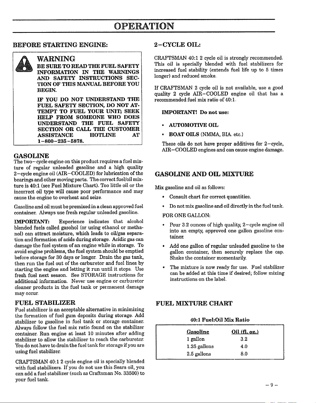
FUEL MIXTURE CHART
40:1 Fuel:Oil Mix Ratio
1 gallon 3_2
1,25 gallons 4,0
2.5 gallons 8.0
-9-
OPERATION
STARTING YOUR ENGINE
(For location of controls, refer to "Specifications.")
BEFORE STARTING THE ENGINE:
• Fuel engine, Move t0 feet (3 meters) away fkom fuel-
ing site_
The.trimmer Ak WARNING
head will turn while starting the
engrne.
o Rest engine and shield on ground, supporting trim-
mer head off ground.
Remove and discard the plastic shipping
guard on the primer bulb (if so equipped)
STARTING A COLD ENGINE OR WARM ENGINE
AFTER RUNNING OUT OF FUEL:
• Make sure the switch is in the "On" position,
• Move the choke lever to the "Full Choke" position.
• Slowly press the primer bulb 6 times,
8 Squeeze and hold the throttle trigger, Keep the
throttle trigger fully squeezed until the engine runs
srnoothly_
e Pull starter rope sharply 5 times.
The engine may sound as if' it is trying to
start before the 5_apull. If so, go to the next step im-
mediately.
e Move the choke lever to the "Half Choke" positian.
® Pull the starter rope sharply until the engine runs,
but no more than 6 pulls,
NOTE: If the engine has not started after 6 pulls (at
half choke), check to make sure the switch and the
choke lever' are in the proper positions Then, move
the choke lever to the "FullChoke' position and
press the primer bulb 6 times; squeeze and hold the
throttle trigger and pull the starter rope 2 more
times. Move the choke lever to "Half Choke" and pull
the starter rope until the engine runs, hut no more
than 6 more pulls.
O
If the engine still has not started, it isprob-
ably flooded. Proceed to "Starting a Flooded En-
gine, 1,
Allow the engine to run 10 seconds, then move the
choke lever to "Off Choke." Allow the unit to run for
30 more seconds at "Off Choke" before releasing the
throttle trigger_
If engine dies with the choke lever at the "Off
Choke': position, move the choke lever to "Half
Choke' and pull the rope until the engine runs_
o To stop the engine, move the switch to "Off,"
A WARNING
Avoid any bodily contact with the muffler when
star. ring a warm engine. A hot muffler can cause
sermus burns.
- 10 -
STARTING A WARM ENGINE THAT HAS NOT
RUN OUT OF FUEL:
• Make sure the switch is in the "On" position.
® Move the choke lever to the "Half Choke" positian,
o Squeeze and hold the throttle trigger. Keep the
throttle trigger fully squeezed until the engine runs
smoothly.
o Pull starter rope sharply until engine runs. but no
more than 5 pulls
o Allow the engine to run 10 seconds, then move the
choke lever to "Off Choke,"
If engine has not started, pull starter rope 5
more pulls, If engine still does not run, it is probably
flooded, Proceed to "Starting a Flooded Engine"
To stop the engine, move switch to the "Off" position
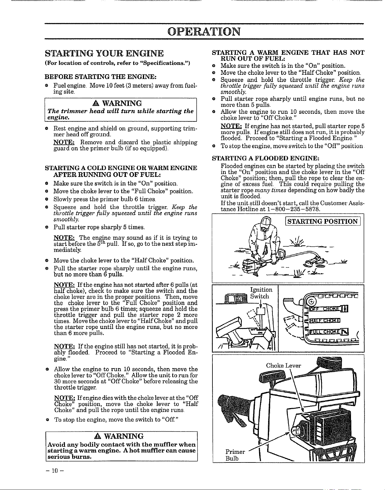
STARTING A FLOODED ENGINE:
Flooded engines can be started by placing the switch
in the "On" position and the choke lever in the "Off
Choke" position; then, pull the rope to clear the en-
gine of' excess fuel, This could require pulling the
starter rope many times depending on how badly the
unit is flooded,
If'the unit still doesnt sta_ t, call the Customei Assis-
tance Hotline at !-800-235-5878.
Ignition
Choke Lever
OPERATING INSTRUCTIONS
e Bring the engine to cutting speed before enter-
ing the material to be cut.
a. Do not run the engine at a higher speed
than necessary. The cutting line will cut effi-
ciently when the engine is run at less than full
throttle, At lower speeds, there is less engine noise
and vibration. The cutting line will last longer
and will be less likely to "weld" onto the spool
e If trimmer head does not turn when the en-
gine is in operation, make sure the tube is prop-
erly seated in the engine shroud.
e Always release the throttle trigger and al-
low the engine to return to idle speed when
not cutting.
o To stop engine:
b. Release the throttle trigger.
c, Move engine switch to the "Off" position.
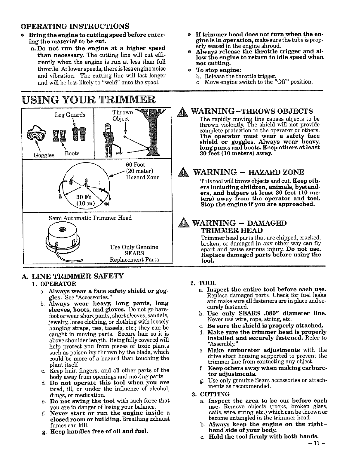
USING YOUR TRIMMER
Leg Guards
wl
\
Goggles Boots
Thrown
Ol_ject
nQ
60 Foot
j(20 meter)
Hazard Zone
Semi Automatic Trimmer Head
Use Only Genuine
SEARS
Replacement Parts
WARNING-THROWS OBJECTS
The rapidly moving line causes objects to be
thrown violently. The shield will not provide
complete protection to the operator or others
The operator must wear a safety face
shield or goggles. Always wear heavy,
longpants and boots. Keep others at least
30 feet (10 meters) away.
WARNING - HAZARD ZONE
This tool will throw objects and cut. Keep oth-
ers including children, animals, bystand-
ers, and helpers at least 30 feet (10 me-
ters) away from the operator and tool.
Stop the engine if you are approached.
A
WARNING - DAMAGED
TRIMMER HEAD
Trimmer head parts that are chipped, cracked,
broken, or damaged in any other way can fly
apart and cause serious injury_ Do not use.
Replace damaged parts before using the
tool.
A. LINE TRIMMER SAFETY
1. OPERATOR
a, Always wear a face safety shield or gog-
gles. See "Accessories,"
b Always wear heavy, long pants, long
sleeves, boots, and gloves. Do not go hare-
foot or wear short pants, short sleeves, sandals,
jewelry, loose clothing, or clothing with loosely
hanging straps, ties, tassels, etc; they can be
caught in moving parts. Secure hair so it is
above shoulder length, Being fully covered will
help protect you from pieces of toxic plants
such as poison ivy thrown by the blade, which
could be more of a hazard than touching the
plant itself.
c. Keep hair, fingers, and all other parts of the
body away from openings and moving parts,
d Do not operate this tool when you are
tired, ill, or under the influence of alcohol,
drugs, or medication
e. Do not swing the tool with such force that
you are in danger of losing your balance.
f, Never start or run the engine inside a
closed room or building. Breathing exhaust
fumes can kill.
g, Keep handles free of oil and fuel.
2. TOOL
a. Inspect the entire tool before each use.
Replace damaged parts Check for fue! leaks
and make sure all fasteners are in place and se-
curely fastened.
b, Use only SEARS .080" diameter line.
Never use wire, rope, string, etc,
c, Be sure the shield is properly attached.
d. Make sure the trimmer head is properly
installed and securely fastened. Refer to
"Assembly"
e Make carburetor adjustments with the
drive shaft housing supported to prevent the
trimmer line from contacting any ol_ject.
f Keep others away when making carbure-
tor adjustments.
g Use only genuine Sears accessories or attach-
ments as recommended
3. CUTTING
a. Inspect the area to be cut before each
use. Remove ol_jects (rocks, broken glass,
nails, wire, string, etc.) which can be thrown or
become entangled in the trimmer head
b. Always keep the engine on the right-
hand side of your body.
c, Hold the tool firmly with both hands.
-11 -
d Keep firm footing and balance. Do not
over-reach.
e Keep the trimmer head below waist level.
f_ Do not raise the engine above your waist.
g. Keep all parts of your bodyaway from the
trimmer line when the engine is running.
h Keep all parts of your body away from a
hot muffler.
i. Use only for jobs explained in this man-
ual.
• A WARN_G
Avmd any bodily contact with the muffler when
starting a warm engine. A hot muffler can cause
serious burns.
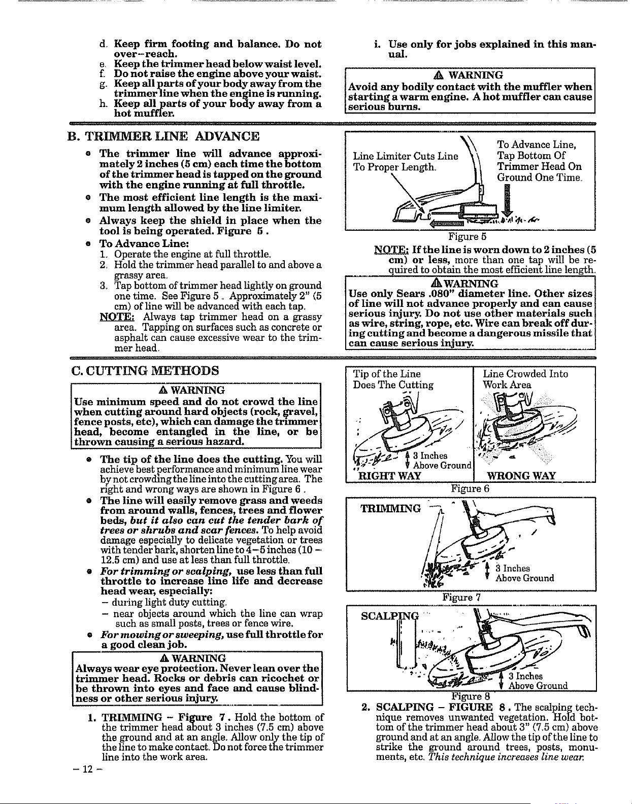
B. TRIMMER LINE ADVANCE
• The trimmer line will advance approxi-
mately 2 inches (5 cm) each time the bottom
of the trimmer head is tapped on the ground
with the engine running at full throttle.
• The most efficient line length is the maxL
mum length allowed by the line limiter.
o Always keep the shield in place when the
tool is being operated• Figure 5.
• To Advance Line:
L Operate the engine at full throttle_
2 Hold the trimmer head parallel to and above a
grassy area.
3. Tap bottom of trimmer head lightly on ground
one time. See Figure 5 • Approximately 2" (5
cm) of line will be advanced with each tap.
NOTE: Always tap trimmer head on a grassy
area. Tapping on surfaces such as concrete or
asphalt can cause excessive wear to the trim-
mer hea4
Line Limiter Cuts Line N_\ T:Ad:_:e L(_e,
To Proper Length. [ / Trimmer Head On
._ Ground One Time_
Figure 5
If the line is worn down to 2 inches (5
cm) or less, more than one tap will be re-
quired to obtain the most efficient line length.
AWARN G
Use only Sears .080" diameter line. Other sizes
of line will not advance properly and can cause
serious injury. Do not use other materials such
as wire, string, rope, etc. Wire can break off dur-
ing cutting and become a dangerous mlssde that
can cause serious injury.
C. CUTTING METHODS
A WARNING ]
Use minimum speed and do not crowd the linel
when cutting around hard objects (rock, _ravel, I
fence posts, etc), which can damage the tmmmer I
head, become entangled in the hne, or be[
thrown causing a serious hazard. ]
• The tip of the line does the cutting. You will
achieve best performance and minimum line wear
by not crowdingthe line into the cutting area. The
right and wrong ways are shown in Figure 6.
• The line will easily remove grass and weeds
from around walls, fences, trees and flower
beds, but it also can cut the tender bark of
trees or shrubs and scar fences. To help avoid
damage especially to delicate vegetation or trees
with tender bark, shorten line to 4-5 inches (10 -
12.5 cm) and use at less than full throttle.
• For trimming or scalping, use less than full
throttle to increase line life and decrease
head wear, especially:
- during light duty cutting.
- near objects around which the line can wrap
such as small posts, trees or fence wire.
• Formowingorsweeping, usefullthrottlefor
a good clean job.
WARNING I
Always wear eye protection. Never lean over the J
trimmer head. Rocks or debris can ricochet or
be thrown rote eyes .and face and cause bhnd-]
ness or other sermus injury. J
1. TRIMMING - Figure 7. Hold the bottom of
the trimmer head about 3 inches (7.5 cm) above
the ground and at an angle. Allow only the tip of
the line to make contact, Do not force the trimmer
line into the work area.
Tip of the Line [ Line Crowded Into
Does The Cutting [ Work Area
RIGHT WAY WRONG WAY
Figure 6
TRIMMING
/
13 Inches
Above Ground
Figure 7
SCALPII_NG ...........
Figure 8 "
2. SCALPING - FIGURE 8. The scalping tech-
nique removes unwanted vegetation. Hold bot-
tom of the trimmer head about 3" (Z5 cm) above
ground and at an angle. Allow the tip of the line to
strike the ground around trees, posts, monu-
ments, etc. This technique increases line wear.
- 12 -
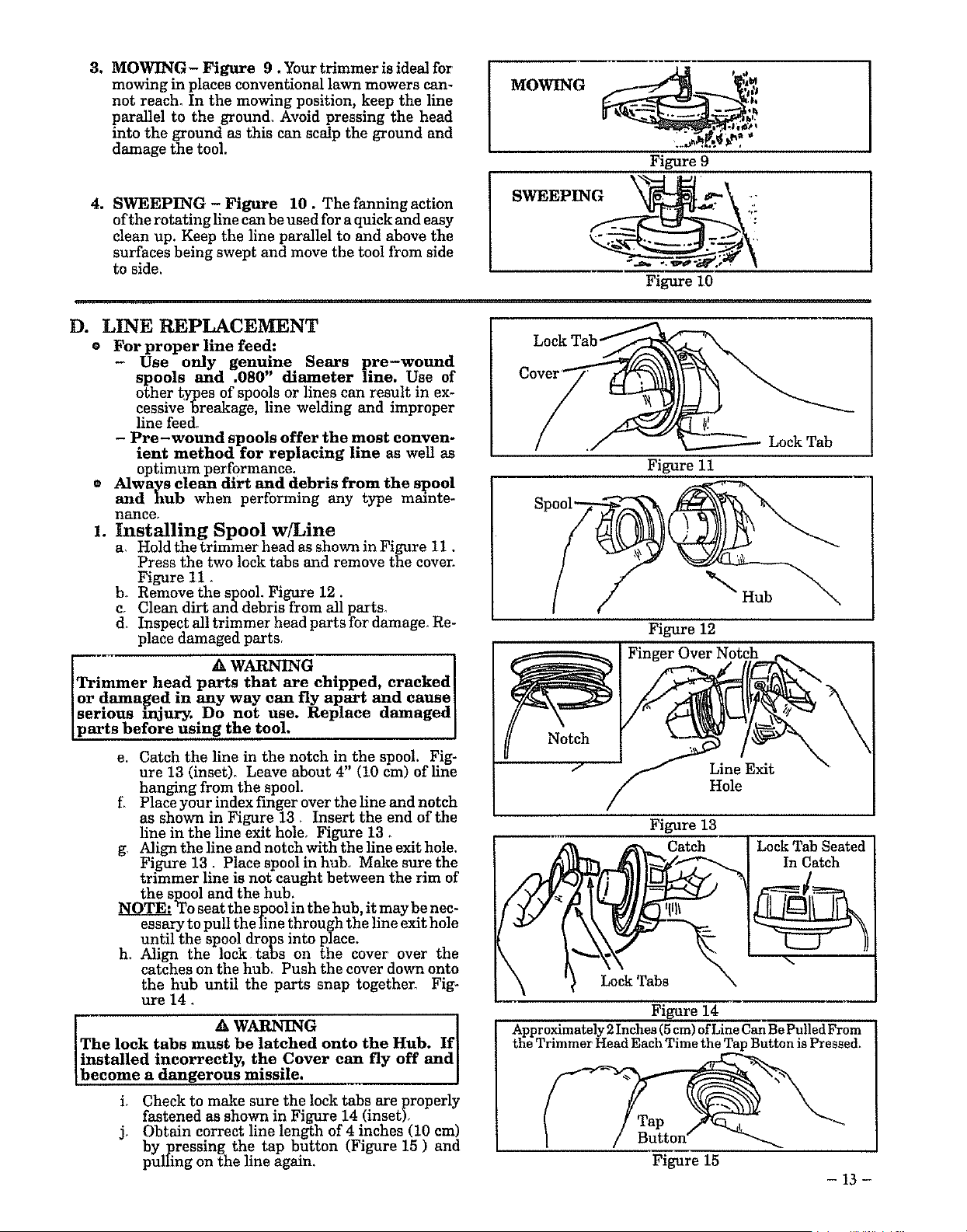
3. MOWING - Figure 9. Your trimmer is ideal for
mowing in places conventional lawn mowers can-
not reach, In the mowing position, keep the line
parallel to the ground_ Avoid pressing the head
into the ground as this can scalp the ground and
damage the tool•
4. SWEEPING - Figure 10. The fanning action
of the rotatingline can be used for a quick and easy
clean up. Keep the line parallel to and above the
surfaces being swept and move the tool from side
to side.
Figure 9
SWEEPINGS, i
Figure 10
D. LINE REPLACEMENT
o For proper line feed:
Use only genuine Sears pre-wound
spools and .080" diameter Hne. Use of
other types of spools or lines can result in ex-
cessive breakage, line welding and improper
line feed.
- Pre-wound spools offer the most conven-
ient method for replacing line as well as
optimum performance.
® Always clean dirt and debris from the spool
and hub when performing any type mainte-
nance,
1. Installing Spool w/Line
a, Hold the trimmer head as shown in Figure 11.
Press the two lock tabs and remove the cover.
Figure 11 •
b_ Remove the spool. Figure 12.
c, Clean dirt and debris from all parts_
d_ Inspect all trimmer head parts for damage_ Re-
place damaged parts,
I _ WARNING ]
Trimmer head parts that are chipped, cracked I
or .damaged in any way can fly apart and cause]
serious injury..Do not use. Replace damaged[
parts before using the tool. ]
e. Catch the line in the notch in the spool. Fig-
ure 13 (inset)_ Leave about 4" (10 cm) of line
hanging from the spool
f_ Place your index finger over the line and notch
as shown in Figure 13 • Insert the end of the
line in the line exit hole, Figure 13
g, Align the line and notch with the line exit hole.
Figure 13, Place spool in hub° Make sure the
trimmer line is not caught between the rim of
the spool and the hub,
NOTE: To seat the spoolin the hub, it may be nec-
essary to pull the line through the line exit hole
until the spool drops into place.
h_ Align the lock tabs on the cover over the
catches on the hub_ Push the cover down onto
the hub until the parts snap together, Fig-
ure 14
IT A WARNING ]
he lock tabs must be latched onto the Hub. If I
]installed incorrectly, the Cover can fly off and]
Ibecome a dangerous missile. [
i, Check to make sure the lock tabs are properly
fastened as shown in Figure 14 (inset)
j, Obtain correct line length of 4 inches (10 cm)
by pressing the tap button (Figure 15 ) and
pulling on the line again.
1,!
Lock Tab
Figure 11
Hub
Figure 12
Finger Over Notch
Notch
f
Line Exit
Hole
Figure 13
Lock Tab Seated
In Catch
Figure 14
Approximately 2 Inches (5 cm) of Line Can Be Pulled From
the Trimmer Head Each Time the Tap Button is Pressed_
Tap
Button"
Figure 15
- 13-
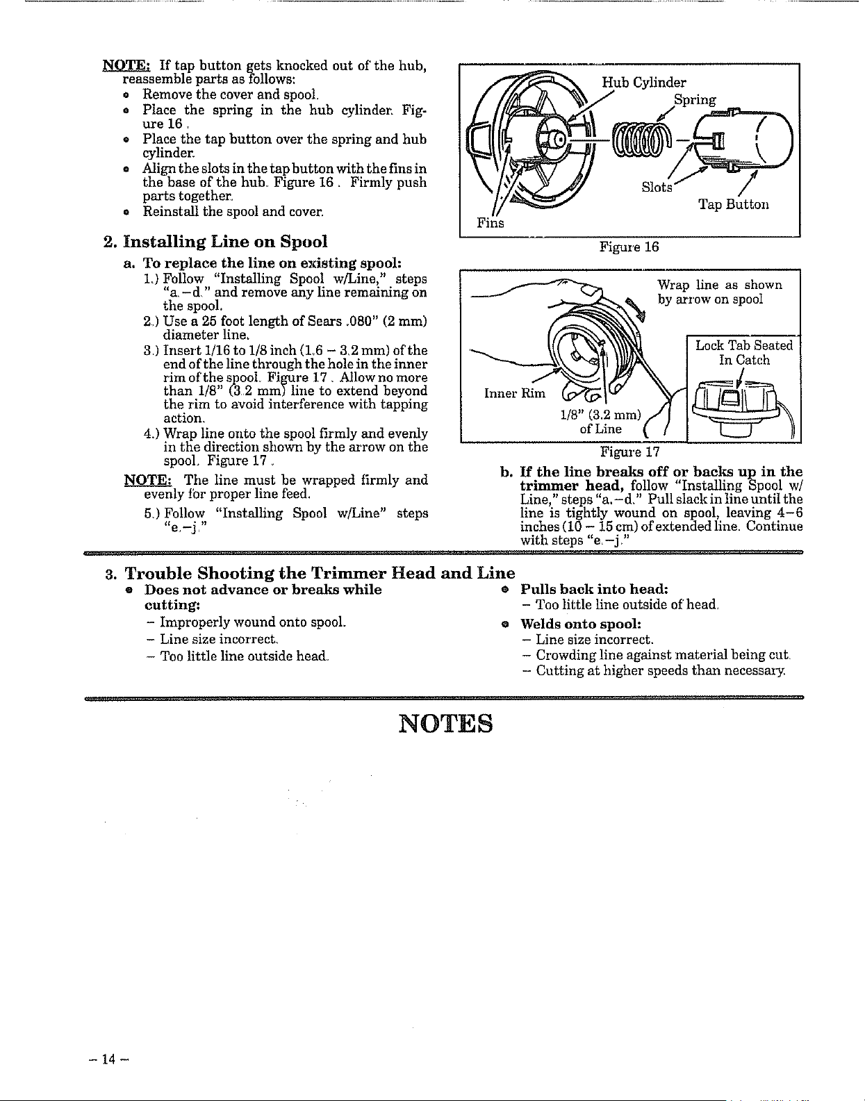
If tapbuttongetsknockedoutofthehub,
reassemblepartsasfollows:
o Removethecoverandspool_
. Placethe springin the hub cylinder,Fig-
ure16.
• Placethetapbuttonoverthespringandhub
cylinder.
e Aligntheslotsinthetapbuttonwiththefinsin
thebaseofthehub_Figure16, Firmlypush
partstogether_
o Reinstallthespoolandcover.
2. Installing Line on Spool
a. To replace the line on existing spool:
L) Follow "Installing Spool w/Line," steps
"a,-d" and remove any line remaining on
the spool.
2) Use a 25 foot length of Sears ,080" (2 mm)
diameter line.
3J Insert 1/16 to 1/8 inch (L6 - 3,2 mm) of the
end of the line through the hole in the inner
rim of the spool Figure 17 Allow no more
than 1/8" (32 mm) line to extend beyond
the rim to avoid interference with tapping
action
4.) Wrap line onto the spool firmly and evenly
in the direction shown by the arrow on the
spool Figure 17
NOTE: The line must be wrapped firmly and
evenly fbr proper line feed.
5) Follow "Installing Spool w/Line" steps
Hub Cylinder
Fins
Figure 16
Inner Rim
Tap Button
Wrap line as shown
by arrow on spool
Lock Tab Seated
In Catch
1/8" (3.2 mm)
of Line
Figure 17
b. If.the line breaks off or backs up in the
trzrnmer head, follow "Installing Spool w/
Line," steps "a.-d?' Pull slack in line until the
line is tightly wound on spool, leaving 4-6
inches (10 - 15 cm) of extended line. Continue
with steps "e,-j ?'
_nra_,ln _qrr_, ........................................................................
3. Trouble Shooting the Trimmer Head and Line
Does not advance or breaks while
cutting:
- Improperly wound onto spool.
- Line size incorrect,
- Too little line outside head_
e Pulls back into head:
- Too little line outside of'head
• Welds onto spool:
- Line size incorrect.
- Crowding line against material being cut,
- Cutting at higher speeds than necessaIT_
NOTES
- 14 -
CUSTOMER RESPONSIBILITY - General Maintenance
A. MAINTENANCE SAFETY
1. Maintain the tool according to recom-
mended procedures. Keep the cutting line at
the proper length.
2, Disconnect the spark plug before perform-
ing maintenance except for carburetor adjust-
ments,
3, Make carburetor adjustments with the low-
er end supported to prevent trimmer line
from contacting any object.
4. Keep others away when making carburetor
adjustments.
5_ Replace trimmer head parts that are
cracked, chipped, broken, or damaged in
any other way before using the unit.
6. Use only .080" diameter SEARS line. Never
use wire, rope, string, etc.
7. Use only genuine SEARS replacement parts
as recommended.
8
Inspect the entire unit. Replace damaged
parts. Check for fuel leaks and make sure all fas-
teners are in place and securely fastened
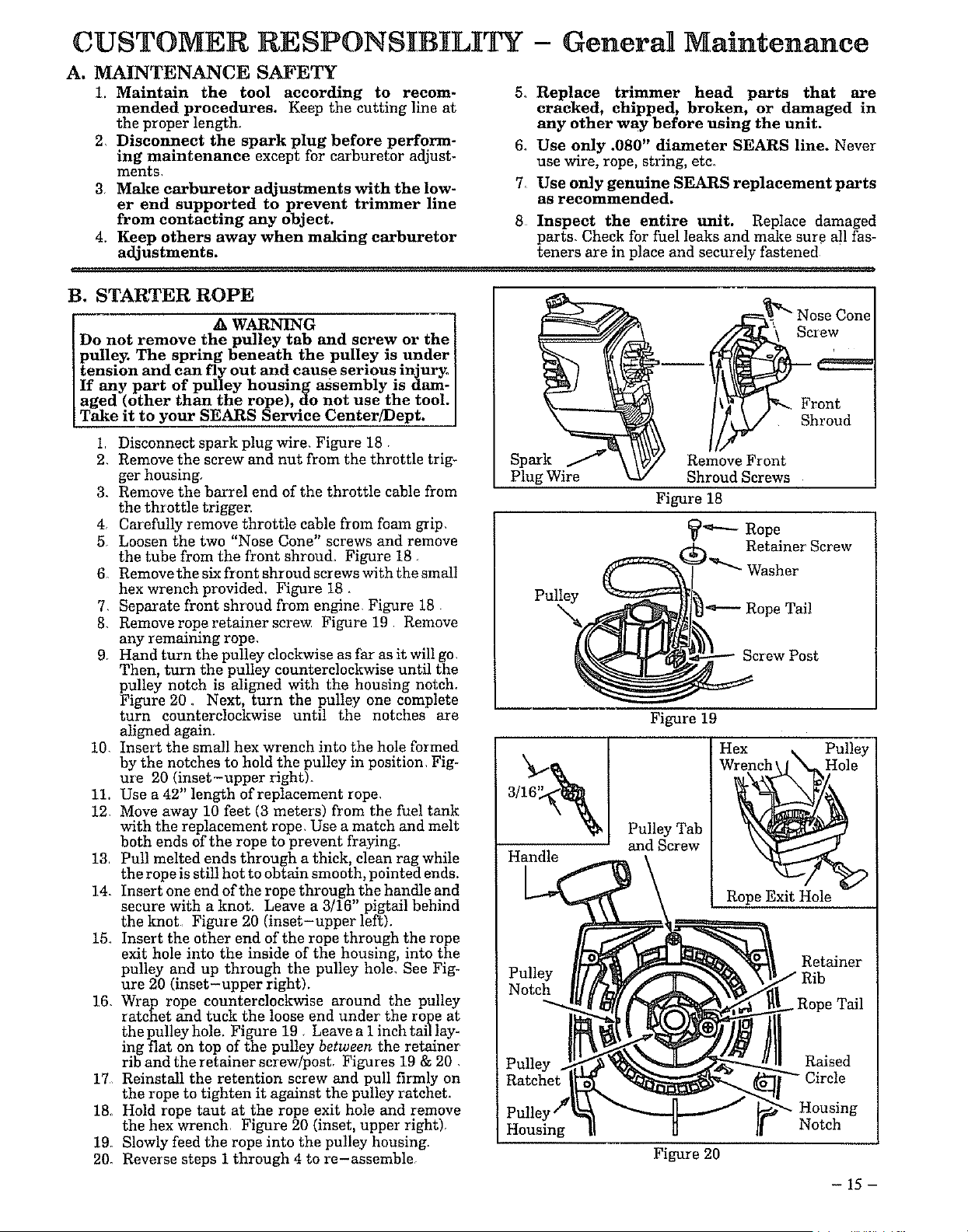
B. STARTER ROPE
A WARNING
Do not remove the pulley tab and screw or the
pulley. The spring beneath the pulley is under
tension and can fly out and cause serious injur_
If any part of pulley housing assembly is dam-
aged (other than the rope), do not use the tool.
Take it to your SEARS Service Center/Dept.
1 Disconnect spark plug wire. Figure 18,
2. Remove the screw and nut from the throttle trig-
ger housing,
3. Remove the barrel end of the throttle cable from
the throttle trigger.
4. Carefully remove throttle cable from foam grip,
5. Loosen the two "Nose Cone" screws and remove
the tube from the front shroud. Figure 18_
6 Remove the six front shroud screws with the small
hex wrench provided. Figure 18 •
7, Separate front shroud from engine. Figure 18
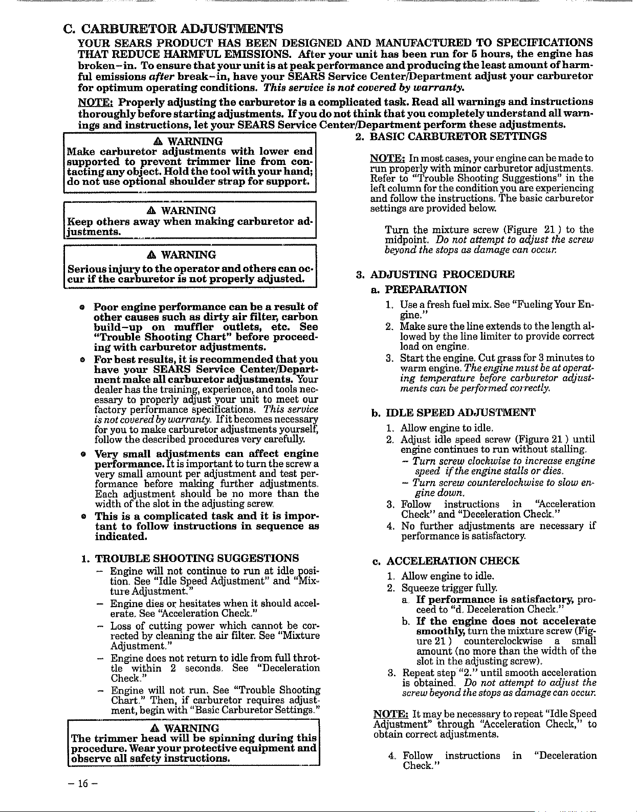
8. Remove rope retainer screw Figure 19 Remove
any remmmng rope.
9r Hand turn the pulley clockwise as far as it will go.
Then, turn the pulley counterclockwise until the
pulley notch is aligned with the housing notch.
Figure 20. Next, turn the pulley one complete
turn counterclockwise until the notches axe
aligned again.
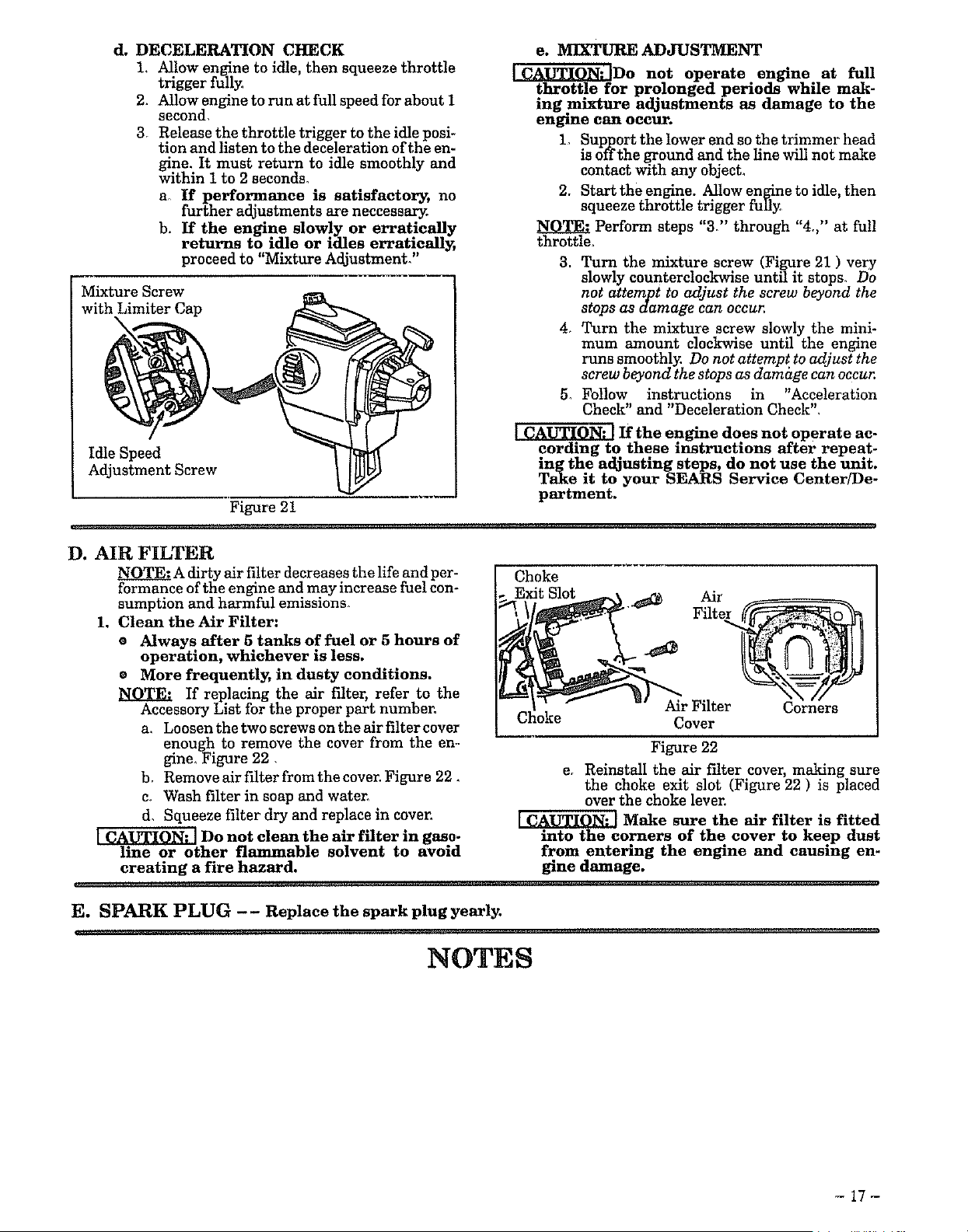
10. Insert the small hex wrench into the hole formed
by the notches to hold the pulley in position, Fig-
ure 20 (inset-upper right).
11. Use a 42" length of replacement rope,
12. Move away 10 feet (3 meters) from the fuel tank
with the replacement rope. Use a match and melt
both ends of the rope to prevent fraying.
13 Pull melted ends through a thick, clean rag while
the rope is still hot to obtain smooth, pointed ends.
14_ Insert one end of the rope through,the handle and
secure with a knot. Leave a 3/16' pigtail behind
the knot Figure 20 (inset-upper left).
15. Insert the other end of the rope through the rope
exit hole into the inside of the housing, into the
pulley and up through the pulley hole, See Fig-
ure 20 (inset-upper right).
16. Wrap rope counterclockwise around the pulley
ratchet and tuck the loose end under the rope at
the pulley hole. Figure 19. Leave a 1 inch tail lay-
ing flat on top of the pulley between the retainer
rib and the retainer screw/pOStr Figures 19 & 20.
17 Reinstall the retention screw and pull firmly on
the rope to tighten it against the pulley ratchet.
18. Hold rope taut at the rope exit hole and remove
the hex wrench, Figure 20 (inset. upper right),
19_ Slowly feed the rope into the pulley housing.
20_ Reverse steps i through 4 to re-assemble.
Plug Wire
Screw
f
Front
Shroud
Remove Front
Shroud Screws
Figure 18
_'_'--- Rope
Retainer Screw
Pulley
Rope Tail
Screw Post
Figure 19
3/16%1
Handle
Pulley Tab
and Screw
Hex _. Pulley
wN
Rope Exit Hole
Retainer
Raised
Housing
Figure 20
Housing
Notch
- 15 -
C. CARBURETOR ADJUSTMENTS
YOUR SEARS PRODUCT HAS BEEN DESIGNED AND MANUFACTURED TO SPECIFICATIONS
THAT REDUCE HARMFUL EMISSIONS. After your unit has been run for 5 hours, the engine has
broken -in. To ensure that your unit is at peak performance and producing the least amount of harm-
ful emissions after break-in, have your SEARS Service Center/Department adjust your carburetor
for optimum operating conditions• This service is not covered by warranty.
_N_QT_FAProperly adjusting the carburetor is a complicated task. Read all warnings and instructions
thoroughly before starting adjustments. If you do not think that you completely understand all warn-
ings and instructions, let your SEARS Service Center/Department perform these adjustments.
WARNING
Make carburetor adjustments with lower end[
supported to prevent trimmer line from con-
]tacting any object• Hold the tool with your hand; ]
Ido not use optional shoulder strap for support. I
Keep others _. WARNING
away when making carburetor ad-
jnstments.
• A WARNING
Serious injury to the operator and others can oc-
cur if the carburetor m not properly adjusted.
2. BASIC CARBURETOR SETTINGS
NOTE: In most cases, your engine can be made to
run properly with minor carburetor adjustments_
Refer to "Trouble Shooting Suggestions" in the
left column for the condition you are experiencing
and follow the instructions_ The basic carburetor
settings are provided below.
Turn the mixture screw (Figure 21 ) to the
midpoint. Do not attempt to adjust the screw
beyond the stops as damage can occur.
3. ADJUSTING PROCEDURE
a. PREPARATION
e Poor engine performance can be a result of
other causes such as dirty air filter, carbon
build-up on muffler outlets, etc. See
"Trouble Shooting Chart" before proceed-
ing with carburetor adjustments.
• For best results, it is recommended that you
have your SEARS Service Center/Depart-
ment make all carburetor adjustments. Your
dealer has the training, experience, and tools nec-
essary to properly adjust your unit to meet our
factory performance specifications. This service
is not covered by warranty. If it becomes necessary
for you to make carburetor adjustments yourself,
follow the described procedures very carefully.
• Very small adjustments can affect engine
performance. It is important to turn the screw a
very small amount per adjustment and test per-
formance before making further adjustments.
Each adjustment should be no more than the
width of the slot in the adjusting screw.
• This is a complicated task and it is impor-
tant to follow instructions in sequence as
indicated•
1. Use a fresh fuel mix. See "Fueling Your En-
gh_e? '
2. Make sure the line extends to the length al-
lowed by the line limiter to provide correct
load on engine.
3. Start the engine. Cut grass fbr 3 minutes to
warm engine. The engine must be at operat-
ing temperature before carburetor adjust-
ments can be peT)Cormed co_Tectly.
b. IDLE SPEED ADJUSTMENT
1. Allow engine to idle.
2. Adjust idle speed screw (Figure 21 ) until
engine continues to run without stalling.
- Turn screw clockwise to increase engine
speed if the engine stalls or dies.
- Turn screw counterclockwise to slow en-
gine down.
3. Follow instructions in '_cceleration
Check" and "Deceleration Check"
4. No further adjustments are necessary if
performance is satisfactory.
1. TROUBLE SHOOTING SUGGESTIONS
- Engine will not continue to run at idle posi-
tion. See "Idle Speed Adjustment" and "Mix°
ture Adjustment,'
- Engine dies or hesitates when it should accel-
erate. See '_cceleration Check."
- Loss of cutting power which cannot be cor-
iected by cleaning the air filter. See 'Mixture
Adjustment."
- Engine does not return to idle from full throt-
tle within 2 seconds_ See "Deceleration
Check."
- Engine will not run. See "Trouble Shooting
Chart?' Then if carburetor requires adjust-
ment, begin with "Basic Carburetor Settings'
p_roec A WARNING ....
trimmer head will be spinning during this
edure. Wear your protective equipment and
[observe all safety instructions.
c. ACCELERATION CHECK
1. Allow engine to idle.
2. Squeeze trigger fully.
a. If performance is satisfactor_ pro-
ceed to "d. Deceleration Check."
b. If the engine does not accelerate
smoothly, turn the mixture screw (Fig-
ure 21 ) counterclockwise a small
amount (no more than the width of the
slot in the adjusting screw).
3. Repeat step "2." until smooth acceleration
is obtained. Do not attempt to adjust the
screw beyond the stops as damage can occur.
NOTE: It may be necessary to repeat "Idle Speed
Adjustment" through "Acceleration Check," to
obtain correct adjustments.
4. Follow instructions in "Deceleration
Check."
- 15 -
d• DECELERATION CHECK
L Allow engine to idle, then squeeze throttle
trigger fully_
2. Allow engine to run at full speed for about 1
second,
3_ Release the throttle trigger to the idle posi-
tion and listen to the deceleration of the en-
twine. It must return to idle smoothly and
thin 1 to 2 secondm
a_ If performance is satisfactory, no
further adjustments are neceessary.
b. If the engine slowly or erratically
returns to idle or idles erratieall_
proceed to "Mixture A_justmenk"
Mixture Screw
with Limiter Cap
Idle Speed
Adjustment Screw
Figure 21
e. MIXTURE ADJUSTMENT
]CAUTION: JDo not operate engine at full
throttle for prolonged periods while mak-
ing mixture adjustments as damage to the
engine can occur.
1, Support the lower end so the trimmer head
is offthe ground and the line will not make
contact with any object_
2. Start the engine. Allow engine to idle, then
squeeze throttle trigger fully,
Perform steps "37' through "4,," at full
throttle_
3. Turn the mixture screw (Figure 21 ) very
slowly counterclockwise until it stops_ Do
not attempt to adjust the screw beyond the
stops as damage can occur.
4, Turn the mixture screw slowly the mini-
mum amount clockwise until the engine
runs smoothly. Do not attempt to adjust the
screw beyond the stops as damage can occur.
5_ Follow instructions in "Acceleration
Check" and "Deceleration Check"
If the engine does not operate ac-
cording to these instructions after repeat-
rng the adjustmgsteps, do not use the umt.
Take it to your SEARS Service Center/De-
partment.
D. AIR FILTER
NOTE: A dirty air filter decreases the life and per-
formance of the engine and may increase fuel con-
sumption and harmful emissions_
1, Clean the Air Filter:
e Always after 5 tanks of fuel or 5 hours of
operation, whichever is less•
® More frequently, in dusty conditions.
If replacing the air filter, refer to the
Accessory List for the proper part numben
a, Loosen the two screws on the air filter cover
enough to remove the cover from the en-
gine_Figure 22,
b, RemoveairfilterfromthecovenFigure 22_
c, Wash filter in soap and waten
d_ Squeeze filter dry and replace in coven
Do not clean the air filter in gaso-
line or other flammable solvent to avoid
creating a fire hazard.
Choke
Exit Slot
Air
"_ Filter_
Air Filter Corners
Cover
Figure 22
e_ Reinstall the air f'flter cover, making sure
the choke exit slot (Figure 22 ) is placed
over the choke lever,
Make sure the air filter is fitted
into the corners of the cover to keep dust
from entering the engine and causing en-
gine damage.
E. SPARK PLUG -- Replace the spark plug yearly.
NOTES
-17-
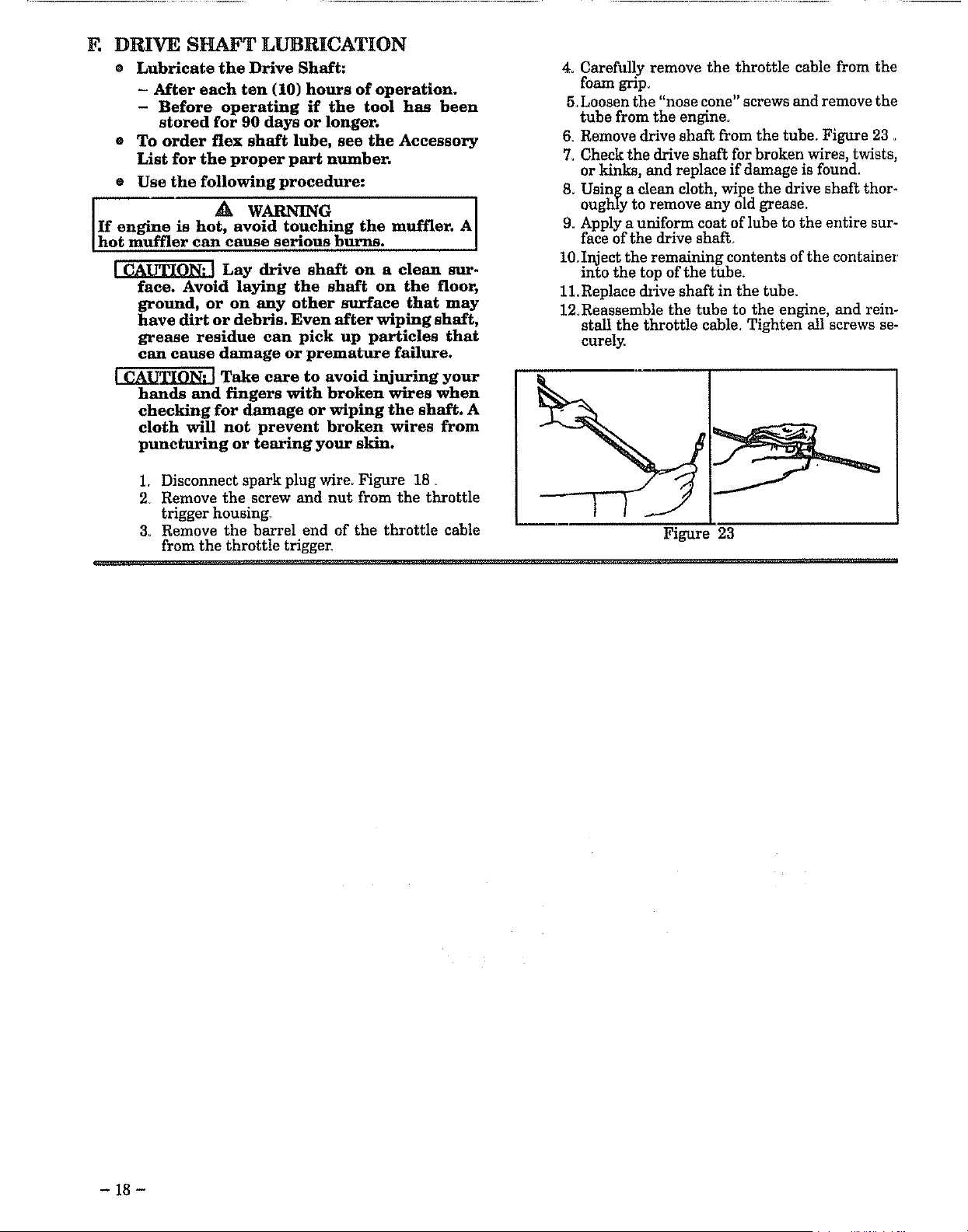
F. DRIVE SHAFT LUBRICATION
® Lubricate the Drive Shaft:
- After each ten (10) hours of operation.
- Before operating if the tool has been
stored for 90 days or longer.
® To order flex shaft lube, see the Accessory
List for the proper part number.
® Use the following procedure:
• A WARNING
If engine is hot, avoid touching the muffler. A
hot muffler can cause serious burns.
Lay drive shaft on a clean sur-
face. Avoid laying the shaft on the floor,
ground, or on any other surface that may
have dirt or debris. Even after wiping shaft,
grease residue can pick up particles that
can cause damage or premature failure.
Take care to avoid injuring your
hands and fingers with broken wires when
checking for damage or wiping the shaft. A
cloth will not prevent broken wires from
puncturing or tearing your skin.
1. Disconnect spark plug wire. Figure 18
2_ Remove the screw and nut from the throttle
trigger housing.
3. Remove the barrel end of the throttle cable
from the throttle trigger.
4. Carefully remove the throttle cable from the
foam grip_
5.Loosen the "nose cone" screws and remove the
tube from the engine.
6_ Remove drive shaft from the tube. Figure 23.
7. Check the drive shaft for broken wires, twists,
or kinks, and replace if damage is found.
8. Using a clean cloth, wipe the drive shaft thor-
oughly to remove any old grease.
9. Apply a uniform coat of lube to the entire sur-
face of the drive shaft
10. Inject the remaining contents of the container
into the top of the tube.
11. Replace drive shaft in the tube.
12_Reassemble the tube to the engine, and rein-
stall the throttle cable. Tighten all screws se-
curely.
Figure 23
- 18-
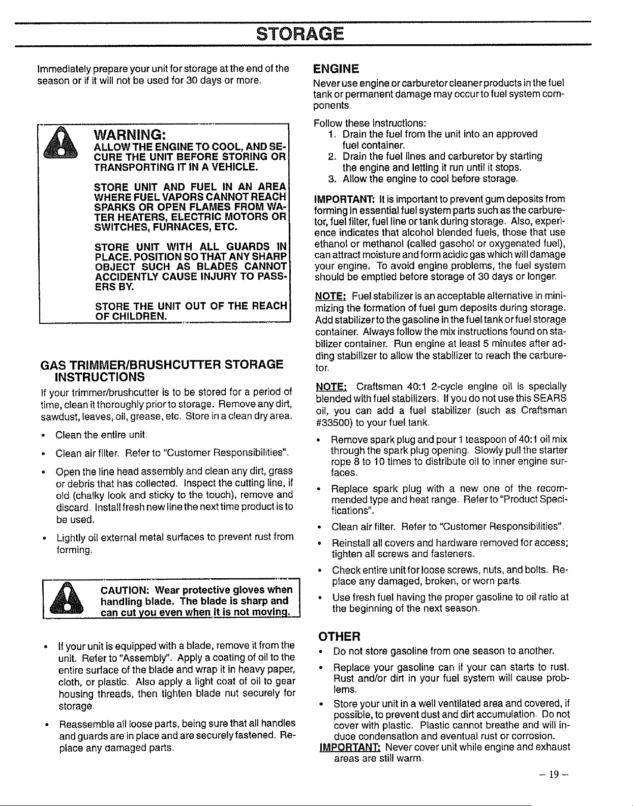
STORAGE
Immediately prepare your unit for storage at the end of the
season or if it will not be used for 30 days or more.
WARNING:
ALLOW THE ENGINE TO COOL, AND SE-
CURE THE UNIT BEFORE STORING OR
TRANSPORTING IT IN A VEHICLE.
STORE UNIT AND FUEL IN AN AREA
WHERE FUEL VAPORS CANNOT REACH
SPARKS OR OPEN FLAMES FROM WA-
TER HEATERS, ELECTRIC MOTORS OR
SWITCHES, FURNACES, ETC.
STORE UNIT WITH ALL GUARDS IN
PLACE. POSITION SO THAT ANY SHARP
OBJECT SUCH AS BLADES CANNOT
ACCIDENTLY CAUSE INJURY TO PASS-
ERS BY.
STORE THE UNiT OUT OF THE REACH
OF CHILDREN.
GAS TRIMMER/BRUSHCUTTER STORAGE
INSTRUCTIONS
If your trimmer/brushcutter is to be stored for a period of
time, clean it thoroughly prior to storage. Remove any dirt,
sawdust, leaves, oil, grease, etc. Store in a clean dry area.
Clean the entire unit.
Clean air filter. Refer to "Customer Responsibilities",
Open the line head assembly and clean any dirt, grass
or debris that has collected. Inspect the cutting line, if
old (chalky look and sticky to the touch), remove and
discard Install fresh new line the next time product is to
be used.
• Lightly oi! external metal surfaces to prevent rust from
forming.
CAUTION: Wear protective gloves when
handling blade. The blade is sharp and
can cut you even when it is not moving. _
If your unit is equipped with a blade, remove it from the
unit. Refer to "Assembly". Apply a coating of oil to the
entire surface of the blade and wrap it in heavy paper,
cloth, or plastic. Also apply a light coat of oil to gear
housing threads, then tighten blade nut securely for
storage,
Reassemble all loose parts, being sure that all handles
and guards are inplace and are securely fastened. Re-
place any aamaged parts_
ENGINE
Never use engine or carburetor cleaner products in the fuel
tank or permanent damage may occur to fuel system com-
ponents,,
Follow these instructions:
1. Drain the fuel from the unit intoan approved
fuel container,
2. Drain the fuel lines and carburetor by starting
the engine and letting it run until it stops.
3. Allow the engine to cool before storage°
IMPORTANT: It isimportantto prevent gum deposits from
forming in essential fuel system parts such as the carbure-
tor, fuel filter, fuel line or tank during storage. Also, experi-
ence indicates that alcohol blended fuels, those that use
ethanol or methanol (called gasohol or oxygenated fuel),
can attract moisture and form acidic gas which will damage
your engine. To avoid engine problems, the fuel system
should be emptied before storage of 30 days or Iongerr
Fuel stabilizer is an acceptable alternative in mini-
mizing the formation of fuel gum deposits during storage.
Add stabilizer to the gasoline in the fuel tank or fuel storage
container. Always follow the mix instructions found on sta-
bilizer container. Run engine at least 5 minutes after ad-
ding stabilizer to allow the stabilizer to reach the carbure-
tor.
Craftsman 40:1 2-cycle engine oil is specially
blended with fuel stabilizers. If you de not use this SEARS
oil, you can add a fuel stabilizer (such as Craftsman
#33500) to your fuel tank.
Remove spark plug and pour 1teaspoon of40:1 oil mix
through the spark plug opening_ Slowly pull the starter
rope 8 to 10 times to distribute oil to inner engine sur-
faces_
Replace spark plug with a new one of the recom-
mended type and heat range Referto "Product Speci-
fications".
• Clean air filter. Refer to"Customer Responsibilities",
° Reinstall all covers and hardware removed for access;
tighten atl screws and fasteners.
• Check entire unit for loose screws, nuts, and bolts, Re-
place any damaged, broken, or worn parts.
• Use fresh fuel having the proper gasoline to oil ratio at
the beginning of the next season.
OTHER
• Do not store gasoline from one season to another.
° Replace your gasoline can if your can starts to rusL
Rust and/or dirt in your fuel system will cause prob-
lems_
• Store your unit in a well ventilated area and covered, if
possible, to prevent dust and dirt accumulation. Do not
cover with plastic. Plastic cannot breathe and will in-
duce condensation and eventual rust or corrosion.
IMPORTANT: Never cover unit while engine and exhaust
areas are still warm.
- 19-

G.TROUBLE SHOOTING CHART
SYMPTOM
Engine will not
start or will run
only for a few
seconds after
starting.
Engine will not
idle properly.
Engine will not
accelerate,lacks
power, or dies
under a load.
Engine
smokes
excessively.
Engine runs hot_
Cutting Head stops
under a load or
does not turn
when engine is
accelerated.
Line does not
advance or breaks
while cutting.
CAUSE
1. Fuel tank empty,
2. Engine flooded,
3. Spark plug not firing.
4. Fuel not reaching carbureton
5. Carburetor requires adjustment,
6, None of the above.
1, Carburetor requires adjustment,
2. None of the above.
L Air filter dirty.
2. Spark plug fouled,
3, Carburetor requires adjustment.
4, Muffler outlets plugged.
5. None of the above.
L Air filter dirty.
2. Fuel mixture incorrect.
3, Carburetor requires adjustment,
1. Fuel mixture incorrect,
2, Carburetor requires adjustment.
3, Spark plug incorrect,
4, None of the above,
I. Drive shaft not engaged,
2, Drive shaft broken,
L Line improperly routed in head.
2_ Line improperly wound onto spool
3. Line size incorrect.
4, Too little line outside head,
5. Dirt accumulated on cover cut-outs.
1, Line size incorrect.
2, Crowding line against materiai being cut.
3. Cutting at higher speed than necessary.
REMEDY
1. Fill tank with correct fuel mixture
2. See "Starting Instructions."
3, Install new plug/check ignition system.
4, Clean fuel filter; inspect fuel line.
5, See "Carburetor Adjustments."
6. Contact your SEARS Service Center/Dept,
1. See "Carburetor Adjustments."
2. Contact your SEARS Service Center!Dept.
L Clean or replace air f'flten
2, Replace spark plug and gap.
3, See "Carburetor Adjustments."
4, Contact your SEARS Service Center/Dept.
5. Contact your SEARS Service Center/Dept,
1, Clean or replace air filter,
2, See "Fueling Your Unit."
3, See "Carburetor Adjustments,"
L See "Fueling Your Unit."
2, See "Carburetor Adjustments,"
3. Replace with correct plug_
4 Contact your SEARS Service Center!Dept,
1. Replace; see '_Assembly".
2, Contact your SEARS Service Center!Dept
1. Remove coven Check line routing_
2, Rewind line tightly and evenly.
3, Use only .080" diameter line.
4_ Remove cover, Pull 4" of line to outside,
5. Clean cover cut-outs,
Line welds on spool, L Use only _080" diameter line.
2, Cut with tip of line.
3, Reduce cutting speed_
Line releases 1. Tap Button engaged. L Remove and clean Tap Button.
continuously.
m
Line usage is 1. Line size incorrect_ L Use only ,080" diameter line_
excessive, 2, Cutting at high speed around hard objects. 2, Reduce speed around hard objects,
3. Crowding line against material being cut, 3. Cut with tip of line,
Line pulls back 1. Too little line outside of head. 1, Remove cover. Pull 4" of line to outside,
into head. 2. Line size incorrect. 2, Use only ,080" diameter line.
- 20 -
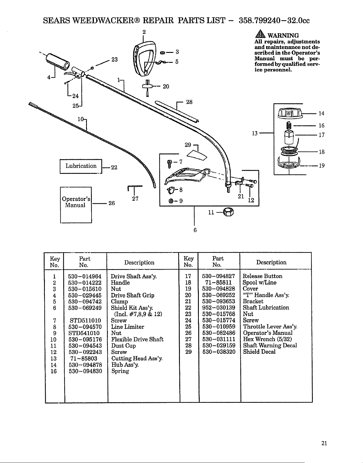
SEARS WEEDWACKER® REPAIR PARTS LIST -
2
358.799240-32.0cc
WARNING
All repairs, adjustments
and maintenance not de-
scribed in the Operator's
Manual must be per-
formed by qualified serv-
ice personnel.
1
Operator's 27
Manual _ 26
20
26
[a 16
17
_.--_-- 19
I
Key [
No. [
-- I
1 I
2 I
3 I
4 ]
5 I
6 I
8 I
9 ]
10 I
11 ]
12
13
14
16
Part
No.
530-014964
530-014222
530-015610
530-029445
530-094742
530-069249
STDSll010
530-094570
STD541010
530-095176
530-094543
530-092243
71-85803
530-094878
530-094830
Description
Drive Shaft Ass'y.
Handle
Nut
Drive Shaft Grip
Clamp
Shield Kit Ass'y.
(Inc!. #7,8,9 & 12)
Screw
Line Limiter
Nut
Flexible Drive Shaft
Dust Cup
Screw
Cutting Head Ass'y.
Hub Ass'y.
Spring
Key
No.
17
18
19
20
21
22
23
24
25
26
27
28
29
Part
No. Description
530-094827
71-85811
530-094828
530-069252
530-093653
952-030139
530-015768
530-015774
530-010959
530-082486
530-031111
530-029159
530-036320
Release Button
Spool w/Line
Cover
"T" Handle Ass'y.
Bracket
Shaft Lubrication
Nut
Screw
Throttle Lever Ass'y.
Operator's Manual
Hex Wrench (5/32)
Shaft Warning Decal
Shield Decal
21
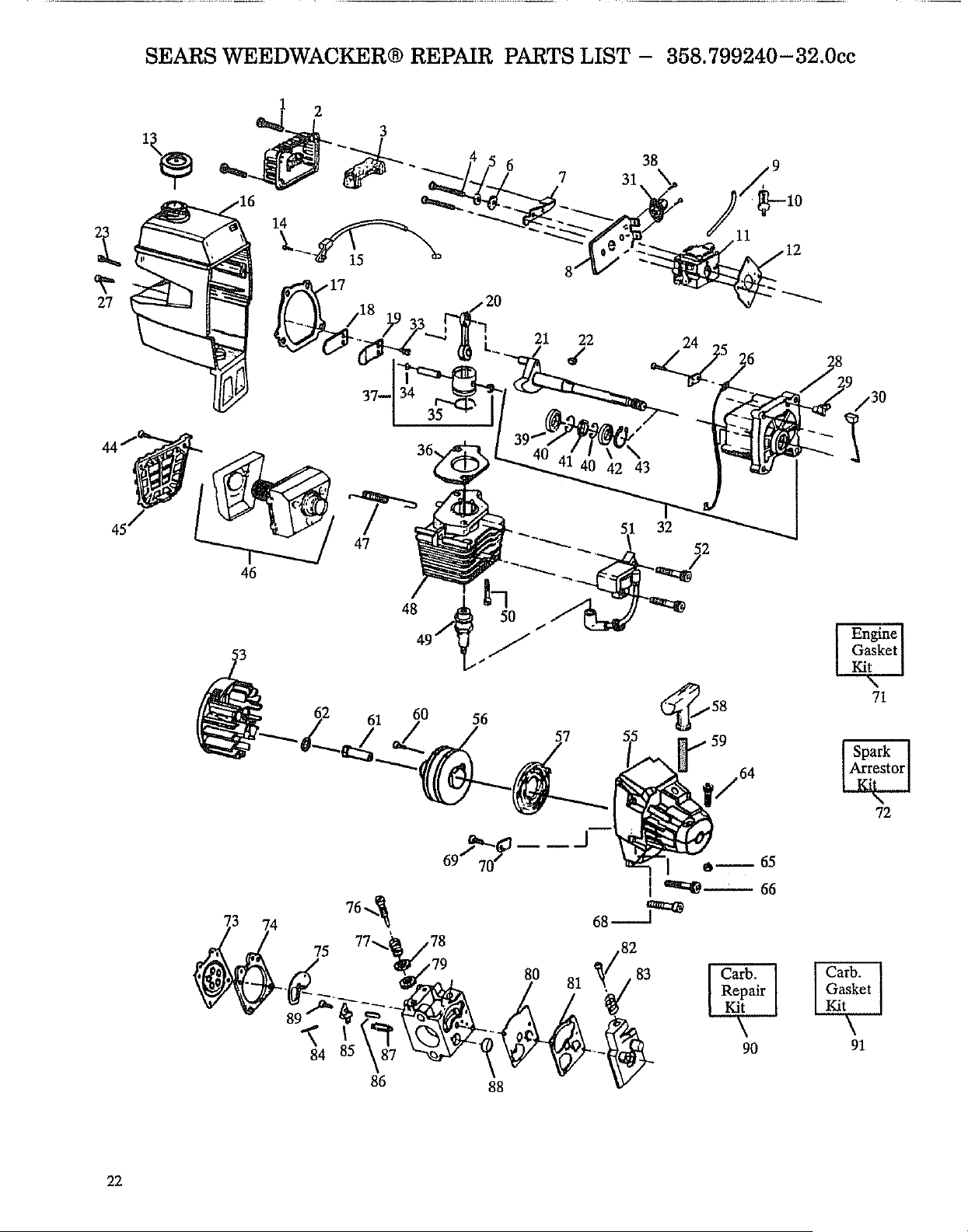
SEARS WEEDWACKER® REPAIR PARTS LIST - 358.799240-32.0cc
,30
I
47
46
48 /_
49 _./
61 60 56
j58
• 59
9O
Engine
Gasket
Kit
71
72
[ Carb. ]
| Gasket I
91
22
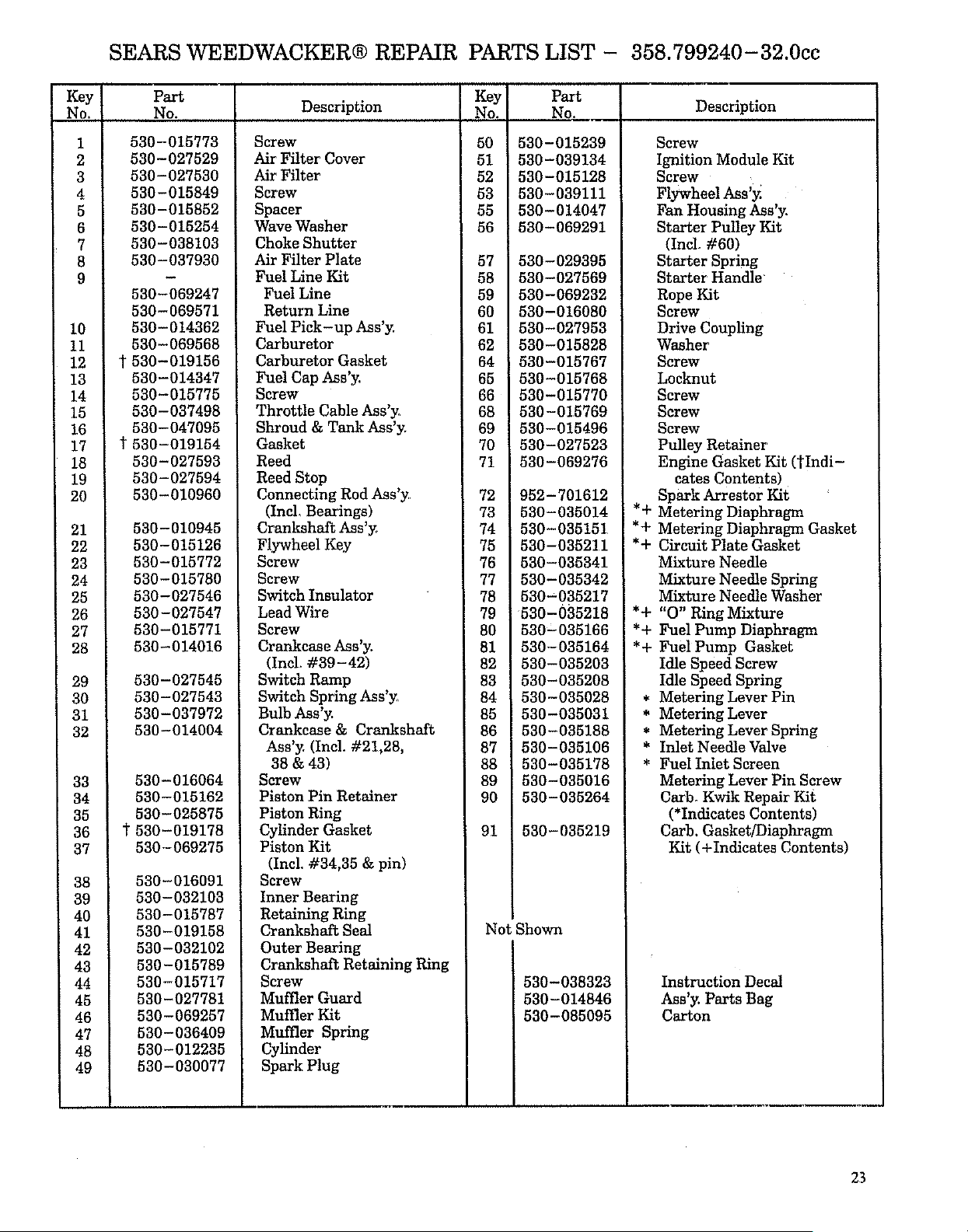
SEARS WEEDWACKER® REPAIR PARTS LIST - 358.799240-32.0cc
Key
No.
1
2
3
4
5
6
7
8
9
10
11
12
13
14
15 !
16
17
18
19
20
21
22
23
24
25
26
27
23
29
30
31
32
33
34
35
36
37
38
39
40
41
42
43
44
45
46
47
48
49
Part
No. Description
530-015773
530-027529
530-027530
530-015849
530-015852
530-015254
530-038103
530-037930
530-069247
530-069571
530-014362
530-069566
t 530-019156
530-014347
530-015775
530-037498
530-047095
t 530-019154
530-027593
530-027594
530-010960
530-010945
530-015126
530-015772
530-015780
530-027546
530-027547
530-015771
530-014016
530-027545
530-027543
530-037972
530-014004
530-016064
530-015162
530-025875
530-019178
530-069275
530-016091
530-032103
530-015787
530-019158
530-032102
530-015789
530-015717
530-027781
530-069257
530-036409
530-012235
530-030077
Screw
Air Filter Cover
Air Filter
Screw
Spacer
Wave Washer
Choke Shutter
Air Filter Plate
Fuel Line Kit
Fuel Line
Return Line
Fuel Pick-up Ass'y.
Carburetor
Carburetor Gasket
Fuel Cap Ass'y.
Screw
Throttle Cable Ass'y_
Shroud & Tank Ass'y.
Gasket
Reed
Reed Stop
Connecting Rod Ass'y`
(IncL Bearings)
Crankshaft Ass'y_
Flywheel Key
Screw
Screw
Switch Insulator
Lead Wire
Screw
Crankcase Ass'y.
(Incl. #39-42)
Switch Ramp
Switch Spring Ass'y.
Bulb Ass'y.
Crankcase & Crankshaft
Ass'y. (Incl. #21,28,
38 & 43)
Screw
Piston Pin Retainer
Piston Ring
Cylinder Gasket
Piston Kit
(Incl. #34,35 & pin)
Screw
Inner Bearing
Retaining Ring
Crankshaft Seal
Outer Bearing
Crankshaft Retaining Ring
Screw
Muffler Guard
Muffler Kit
Muffler Spring
Cylinder
Spark Plug
Key
No.
50
51
52
53
55
56
57
58
59
60
61
62
64
65
66
68
69
70
71
72
73
74
75
76
77
78
79
80
81
82
83
84
85
86
87
88
89
90
91
Part
No. Description
530-015239
530-039134
530-015128
530-039111
530-014047
530-069291
530-029395
530-027569
530-069282
530-016080
530-027953
530-015828
530-015767
530-015768
530-015770
530-015769
530-015496
530-027523
530-069276
952-701612
530-035014
530-035151
530-035211
530-035341
530-035342
530-035217
530-035218
530-035166
530-035164
530-035203
530-035208
530-035028
530-035031
530-035188
530-035106
530-035178
530-035016
530-035264
530-035219
Not Shown
530-038323
530-014846
530-085095
Screw
Ignition Module Kit
Screw
Flywheel Ass'y:
Fan Housing Ass'y.
Starter Pulley Kit
(Incl. #60)
Starter Spring
Starter Handle"
Rope Kit
Screw
Drive Coupling
Washer
Screw
Locknut
Screw
Screw
Screw
Pulley Retainer
Engine Gasket Kit (tIndi-
cates Contents)
Spark Arrestor Kit
*+ Metering Diaphragm
*+ Metering Diaphragm Gasket
*+ Circuit Plate Gasket
Mixture Needle
Mixture Needle Spring
Mixture Needle Washer
*+ "O" Ring Mixture
*+ Fuel Pump Diaphragm
*+ Fuel Pump Gasket
Idle Speed Screw
Idle Speed Spring
* Metering Lever Pin
* Metering Lever
* Metering Lever Spring
* Inlet Needle Valve
* Fuel Inlet Screen
Metering Lever Pin Screw
Carb. Kwik Repair Kit
(*Indicates Contents)
Carb. Gasket/Diaphragm
Kit (+Indicates Contents)
Instruction Decal
Ass'y. Parts Bag
Carton
23
8E__/A/ 8
Operator's
Manual
Model No.
358.799240-32cc
How to Order
Repair Parts
SEARS SERVICE
IS AT YOUR SERVICE
The Model Number will be found below the top handle with the Serial
Number. Always mention the Model Number when requesting service
or repair parts for your unit.
All parts listed herein may be ordered from any Sears Service Center
and most Sears Stores.
WHEN ORDERING REPAIR PARTS ALWAYS GIVE THE FOLLOW.
ING INFORMATION AS SHOWN IN THIS LIST:
L The PART NUMBER
2. The MODEL NUMBER
358.799240-32cc
3. The PART DESCRIPTION
4. The NAME OF ITEM --
32cc Gas Weedwacker
If the parts you need are not stocked locally, your order will be trans-
mitted to a Sears Repair Parts Distribution Center for handling.
When you buy merchandise from
Sears you get an extra value that
nobody else can offer --
Sears Service.
Across town or across the country,
Sears Service is always near, pro-
vidlng trustworthy, competent
service technicians using only
Sears specified factory parts.
Your Sears Merchandise takes on added value when you discover
that Sears has Service Units throughout the country. Each is
staffed by Sears-Trained, professional technicians using Sears
approved methods.
Sears, Roebuck and Co., Hoffman Estates, IL 60179 USA
PRINTED IN U.S.A.