Loading ...
Loading ...
Loading ...
3
Planning the Installation
WARNING
• IMPORTANT: Observe all governing codes and ordinances
during planning and installation. Contact your local building
department for further information.
• To prevent an electric shock hazard, the power supply
must meet the specifications stated below. It is the owner’s
responsibility to make sure that the electrical service meets
electrical requirements and that the electrical outlet has
been properly installed by a licensed electrician.
The appliance installation must be electrically grounded in
accordance with local codes or, in the absence of local codes,
with the National Electrical Code, ANSI/ NFPA 70:
Electrical Requirements
• The range is supplied with a factory installed, 6 foot long,
power cord with a three-prong grounding plug. It is connected
to the chassis at the rear of the range. It must be connected
to a dedicated, grounded three-prong electrical outlet.
• The correct voltage, frequency and amperage must be
supplied to the appliance from a separate, grounded, circuit
that is protected by a properly sized circuit breaker or time
delay fuse.
Model Circuit Required
Total
Connected
Load*
RNRP36G
120 Vac, 60 Hz, 15 Amp.
120 Vac 60 Hz,
5.0 Amp.
RNRP48G
120 Vac, 60 Hz, 15 Amp.
120 Vac 60 Hz,
8.0 Amp.
*These specifications for reference only. Refer to the rating label
for exact specifications (see below for location).
Gas Supply Requirements
• The installation of this appliance must conform with local
codes or, in the absence of local codes, with the National
Fuel Gas Code, ANSI Z223.1/NFPA 54.
• Be certain that the appliance being installed is correct for
the gas service provided (natural gas or LP gas). Also, if
operating the range at an altitude above 4000 ft. (1219 m)
make sure it is equipped for high altitude operation. Refer
to the range rating label and the table on the inside cover to
determine the correct model.
• See the table below for gas supply pressure requirements.
• The range comes from the factory with the regulator
installed. Use only the installed regulator. The regulator inlet
accommodates a 3/4” gas line. The range ships with a 1/2” to
3/4” adapter connected to the regulator.
GAS SUPPLY PRESSURE REQUIREMENTS*
Gas Type
Minimum
Manifold Pressure
Minimum Gas
Supply Pressure**
Natural Gas 5” Water Column 6” Water Column
Liquid Propane (LP) 10” Water Column 11” Water Column
* The gas supply pressure for testing the regulator setting shall
be at least 1 inch water column (249 Pa) above the specified
manifold pressure.
** Maximum gas supply pressure for all models: 1/2 psi.
The ratings above are for reference only. Refer to the rating label
for exact specifications (see below left for location).
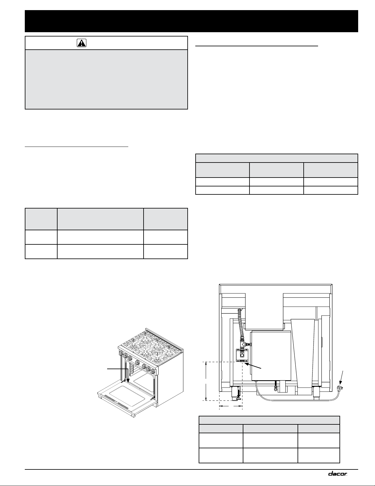
B
A
Power
cord
Gas
Inlet
GAS - ELECTRICAL ACCESS DIMENSIONS
Model A B
RNRP36G
13 1/16” to 14 3/8”
(33.2 to 36.5 cm)
7 5/16”
(18.6 cm)
RNRP48G
13 1/16” to 14 3/8”
(33.2 to 36.5 cm)
4 1/4”
(10.8 cm)
Specifications Label Location
View rating label through slot on
top of kick panel through opening
between door and range
Loading ...
Loading ...
Loading ...